Lupine Publishers Group
Lupine Publishers
Menu
ISSN: 2690-5779
Review Article(ISSN: 2690-5779) 
Anti-Fatigue Design for Powered Roof Supports Volume 1 - Issue 4
Tadeusz Łagoda1*, Monika Polak-Micewicz2
- 1Faculty of Mechanical Engineering, Department of Mechanics and Machine Design, Opole University of Technology, Poland
- 2Famur Institute, Katowice, Poland
Received: March 18, 2021 Published: March 26, 2021
Corresponding author: Tadeusz Łagoda, Faculty of Mechanical Engineering, Department of Mechanics and Machine Design, Opole University of Technology, Poland
DOI: 10.32474/JOMME.2021.01.000119
Abstract
A powered roof support is defined a set of support sections arranged next to each other, which creates space for mining and transportation machines and also for staff. The housing protects the newly discovered ceiling by moving a distance equal to the width of the mining body. The powered roof supports (PRS) must keep roof in variable cycle loads in mine and then it can lead to a complex combination of physical occurrences and changes in the construction. Micro-damages arising as a result of cyclical loads gradually develop and accumulate, leading to fatigue cracking. This paper presents an approach for the complexity of powered roof supports design taking into account fatigue life. In the work there can also be found some information on existing notches and how they are taken into account in the calculation. The main purpose of the work was to develop such an anti-fatigue design methodology to make calculations using the elastic model, and then at critical points apply the local elastic-plastic model methods using the Neuber model. Next there were adopted the appropriate fatigue criteria to determine fatigue life wall housing. To obtain the final form of the algorithm in this paper there are different fatigue tests presented, including: tests of wall casings with strain gauges and numerical analyzes using finite element method. Based on the tested main subassemblies of the PRS, the most effective method was defined taking into account the average values of cycle amplitudes, and the next step determined the degree of damage for all load supports. The results from experiments allow determining durability of critical places for the main subassemblies of the PRS and determining the most stressed components. Due to the shortage of systematic procedures and guidelines for the strength calculations of PRS enclosure which would take into account fatigue life, the proposed method meets the expectations of a correct and full recognition of static and fatigue strength analyzes.
Keywords: Life-Time; S-N Curve; Stress Concertation; FEM
Introduction
The movement of a powered roof support section behind the
progressing coalface results in a cyclical change of its load. During
each technological cycle in the wall we can discern the following
stages of load: expanding, propping the load from the rock mass,
caving. This cycle is repeated during coal mining, which leads to
variable stresses in the powered roof support structure. It should
be remembered that caving occurs behind the roof support, i.e.
the collapse of rocks, which may also cause the appearance of
dynamic effects on the anti-collapse support, which is omitted
during laboratory tests. The fatigue strength of roof support
components should be determined at the design stage, as they are
not expected to be replaced during their lifetime inside a mine. It
is therefore necessary to correctly estimate the number of cycles
beyond which damage may occur in the stress concentration area
of a given roof support component. The basic legal instruments
ensuring safety are directives and standards: European (EN 1804-
1:2001+A1:2011), American (CONSOL method) or Russian (GOST
R 52152-2003), which describe in detail the testing plan, including
loads and number of fatigue cycles, which are carried out at a test
stand in an accredited certification laboratory.
Fatigue testing of the prototype section of the longwall powered
roof support is mainly based on laboratory tests. Nowadays,
tendencies among domestic clients are observed to increase the
number of cycles up to 60,000 cycles. After testing according
to a European standard, the number of cycles for each support
block is proportionally increased to reach the expected number
of cycles. Bench tests allow to recognize the mechanism of crack
formation and precisely determine the durability of the structure,
therefore the measurement data from strain gauges are recorded,
thus enabling to recognize the nature of strain in the predicted
area of crack initiation. The most popular and simplest approach
to determining the fatigue limit is to know the dependence of stress amplitude on the number of cycles, so called Wöhler’s or
Basquin’s diagram. However, relying solely on these diagrams in
the case of the powered roof support is a very large simplification,
which omits, among other things, geometric notches, structural
notches and average values of cycles. A literature review on multiaxial
cyclic fatigue shows that there is no single universal stress
criterion for different load conditions. Therefore, one of the main
objectives of this work is to attempt durability assessment using
numerical analysis based on the finite element method and to adopt
an appropriate fatigue criterion in order to determine the most
exposed area on this basis, while at the same time identifying the
component most exposed to potential failure.
Characteristics of powered roof support tests
Experimental research on the powered roof support was
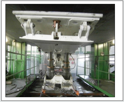
carried out in the Technical Laboratory in Opava (Figure 1) and
lasted until the moment of visible damage to the structure. The
appearance of cracks threatening the safety of continued testing
resulted in stopping the tests and the final determination of the
durability. The research method was presented in the works [1 - 9],
and the applied criterion of multi-axial fatigue was described in the
work [10]. It should be emphasized that although laboratory tests
do not fully reflect the actual conditions in the mine underground,
the variety of supporting actions and the number of cycles in the
stress tests usually exceeds the actual operation of the powered
roof support. Such a conclusion was reached after long-term
observations of the powered roof support during its examination,
operation and servicing.
The results obtained from experimental studies were used to
determine elastic and elastic-plastic strain according to the formula
below:
Results
The vegetation diversity and ecological spectrum of rare plant species
Post-industrial particular post-mineral exploitation sites,
especially those subjected to spontaneous succession are
characterized by specific habitat conditions, and thus unique
biocoenoses arise on those habitats [18]. They are often
characterized by a high number of species (biodiversity). Over
500 plant species were recorded on the post-coal mine heaps and
sedimentation [18, 23-25]. Apart from the post-coal mine sites
the vascular plant species flora of quarries, gravel and sand pits,
post coal-mine heaps and dumps present high floristic richness,
including the occurrence of rare and endangered species.
The long term study on the conditions influencing of the
diversity of spontaneous vegetation on post coal-mine heaps in
Upper Silesia have shown that vegetation diversity is changing
in time. The spontaneous vegetation is most diverse in the initial
stages of post-coal mine heaps ecosystem development (Figure 1).

where:
εat - amplitude of total strain,
εae - amplitude of elastic strain,
εap - amplitude of plastic strain.
In the cycle of alternating stresses sinusoidally one can distinguish: maximum stresses of the cycle σmax, minimum stresses
of the cycle σmin, stress amplitude σa, average stress of the cycle σm,
stress change interval T or frequency f. Each stress amplitude σa or
maximum stress σmax shall be matched by the number of destructive
cycles Nf until the stress amplitude σa drops to the fatigue limit at
the specified number of Nf.
In the first step, from the Ramberg-Osgood equation, the curve
of cyclic strain is determined:

where:
E- Young’s modulus,
σa –stress amplitude,
K’ - the coefficient of cyclic strain hardening,
n’ - the exponent of cyclic strain hardening.
The next step is to determine the extremes of the function
waveforms for a given type of supporting action, followed by stress
amplitudes and mean values according to the following formula:
- stress amplitude σa

- average value σm

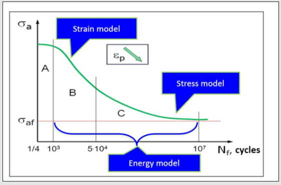
Based on the characteristics prepared from Basquin correlation and material data, the fatigue limit with respect to the crack area can be most easily determined. Thus, three areas can be distinguished depending on stress levels and number of cycles: quasi-static, low cycle (LCF) and high cycle (HCF), for which appropriate multi-axial fatigue criteria are used: strain, stress and energy model combining the two previously mentioned factors (Figure 2).
It should be remembered that there are no clearly defined
boundaries between quasi-static and low cycle or low cycle and
high cycle strength. Experience shows that the first cracks may
occur primarily in the weld areas [11] and that these places should
be properly designed using available tools such as numerical
programs (e.g. ANSYS, ABAQUS), Welding Institute guidelines [12],
or British standards describing permissible fatigue stresses in
welded joints [13].
Welded joints are classified as notched elements. Their
evaluation is hindered not only by the local geometry but also by
the microstructure and residual stresses caused by the welding
process[10]. The methods used to estimate the durability of
notched elements, and welded joints undoubtedly belong to
notched elements, can be divided into local and non-local (global).
Both methods can be further divided into those based on stress
using the elastic body material model and those using the elasticplastic
body model dependencies. When considering the initiation
of fracture, it is most often assumed that the initiation takes place
at the notch surface. At this point, local stress usually takes on high
values and calculated durability often indicates significantly fewer
cycles to failure [14, 15]. Global methods most often use the fatigue
factor of notch effect Kf whose dependence is based on fatigue
characteristics determined in laboratory tests.
For welded joints, the average stress value can be considered
to have no significant effect on fatigue life. Łagoda in the work [16]
presents the results of welded joint tests. They produced practically
identical fatigue diagrams for symmetrical and pulsating loads.
This is probably due to the existing high residual stresses. Fatigue
strength is relatively slightly dependent on the type of welded joint
being analyzed, but is more affected by the type of load, the quality
of the weld and its size.
One of many methods of determining the durability of notched
elements is to determine the theoretical factor of notch effect Kf
(αk - according to Polish literature). This parameter is based on the
stress or strain at points of the concentration of stress or strain.

where:
σmax, εmax - maximum stress or strain in the notch,
σn, εn - nominal stress or strain.
If elastic-plastic strain is present in the notch, the Kt factor shall
be determined as the geometric mean according to the Neuber rule
by means of factors of stress and strain concentration.

while e p max ε − and e p max σ − are the local maximum elastic-plastic strain and the normal stress in the elastic-plastic model respectively [16]. In order to estimate the fatigue life of components containing both geometric and structural notches, methods based on the fatigue coefficient of notch effect Kf can be used, the value of which can be determined from the correlation:

where:
σsm - amplitude of nominal stresses in elements without
geometric notch,
σnot - amplitude of nominal stresses in notched elements.
On the basis of fatigue tests carried out for medium strength steels such as S355N, Biłous in the paper [17] proved that for the range of a large number of cycles these steels weaken, and highstrength steels (e.g. S690Q) tend to strengthen with the increasing number of cycles. This conclusion can have a significant impact on the design and selection of the welded joint, especially in the area of the leg pockets.
Example of fatigue life assessment of roof supports
To determine the fatigue life, the degree of failure must be calculated using one of the many damage accumulation hypotheses. In this paper, Palmgren-Miner linear rule [18] was applied, in which it was assumed that each fatigue cycle with specified parameters gives failure equal to the inverse of the total number of cycles causing failure. This function can be written in the form:

where:
- Ni is the number of cycles for subsequent supporting actions,
- ni is the number of repetitions of tests for subsequent
supporting actions.
According to this hypothesis, damage occurs when the total
portions of damage reaches the value of 1.
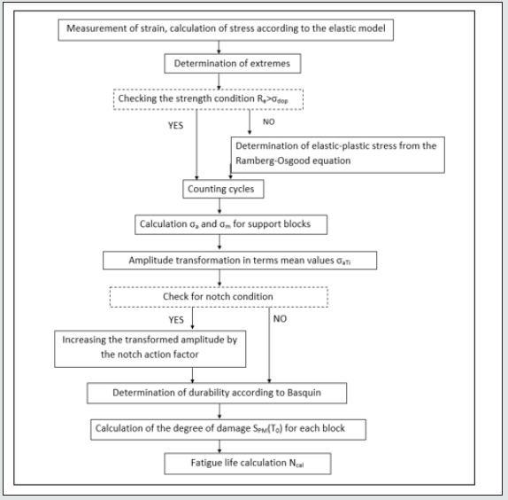
The following is a general algorithm [19] for fatigue life
determination using Basquin characteristics (Figure 3).
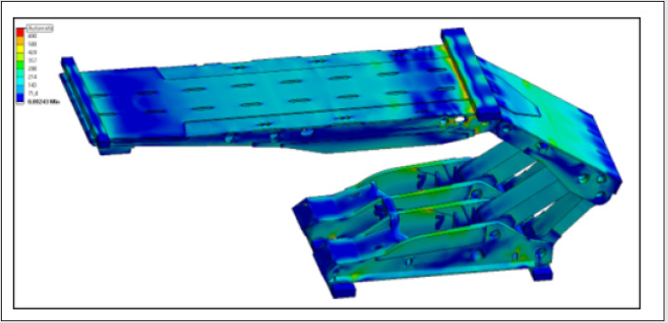
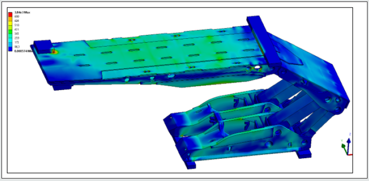
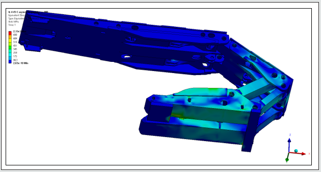
The calculation of effective support stresses, especially in the areas of welded joints, requires the use of FEM. In previous works [20], calculations were carried out for individual structural elements. An attempt was made to determine fatigue life based on the FEM results of the structure as a whole, with appropriate contact points and coefficients of friction between the bending loading blocks (Figures 4 - 6).
Simulation tests carried out on all types of propping actions for the standard prototype roof support in the laboratory showed that the designed structure will last more than 100,000 cycles. Calculated life values showed that the design would meet the high fatigue strength requirements for an increased number of cycles, and that local cracks may occur due to other factors unrelated to the manufacture of the powered roof support.
Conclusion
The presented method and conclusions resulting from
the simulation calculations are only a fragment of a complex
methodology of predicting the durability of a longwall powered
roof support. The strength analyses are continuously modified on
the basis of further laboratory tests in order to be able to precisely
determine the degree of damage in the individual areas of the
structure in the future and to optimize them.
Determination of critical points of the components of powered
roof support section and further determination of fatigue life
may constitute a significant step towards the development of a
methodology for tailoring a longwall roof support according to
the client’s requirements and for increasingly difficult mining and
geological conditions in which it will be used. It may also allow not
only to update the methodology of roof support selection in Poland,
in line with the development of knowledge and tools currently
available in the world, but may also be a step ahead of the solutions
existing in the best scientific and research centers worldwide
concerning the selection and reliability for powered roof supports.
References
- Jaszczuk M, Markowicz J, Szweda S (2009) Ocena wytężenia elementów podstawowych sekcji obudowy zmechanizowanej przy różnym sposobie jej obciążenia, Komtech, Innowacyjne, bezpieczne oraz efektywne techniki i technologie dla górnictwa człowiek - maszyna - środowisko, Gliwice, pp. 347-355.
- Okrajni J, Plaza M, Markowicz J (2010) Opis procesu odkształcenia elementów obudowy zmechanizowanej, XXIII Sympozjum Zmęczenie i Mechanika Pękania, Bydgoszcz-Pieczyska, pp. 351-352.
- Hussein MA, Ibrahim AR, Imbaby SS (2013) Load calculations and selection of the powered support basedon rock mass classification and other formulae for Abu-Tartur longwall phosphate mining conditions, Journal of Engineering Science 41(4): 1728 – 1742.
- Jesiulek D (2019) Monitoring the operational parameters of a power roof support. Journal of Machine Construction and Maintenance pp.109-115.
- Yetkin ME, Simsir F, Ozfirat MK, Ozffirat PM, Yenice H (2016) A fuzzy approach to selecting supports in longwall mining. South Africa Journal of Industrial Engineering 27(1): 162-177.
- Rajwa S, Janoszek T, Prusek S (2019) Influence of canopy ratio of powered roof support on longwall working stability – A case study. Int J of Mining Science and Technology 29(4): 591-598.
- Kumar C(2014) Behavior of shield support in longwall mining, National Institute of Technology, Rourkela, India p. 56.
- Szurgacz D, Brodny J (2019) Application of a roof support monitoring system for analysis of work parameters of a powered longwall system. E3S Web of Conferences 105: 1-7.
- Michalak M (2007) Modelling of powered roof support work. Int J of Environmental and Ecological Engineering 5: 603-608.
- Michalak M (2014) Gradual-randomized model of powered roof supports working cycle, Computer Science and Information Technology, Eds. NMeghanathan et al. p.15-24.
- Polak- Micewicz M, Łagoda T, Khair Abdul W (2012) Determination of the Strength of Powered Roof Supports According for Fatigue Life. USA – 31st International Conference on Ground Control in Mining, West Virginia University, United States.
- Łagoda T (2008) Lifetime estimation of welded joint. Springer.
- Savaidis G, Vormwald(2000) MHot-spot stress evaluation of fatigue in welded structural connections supported by finite element analysis. Int J Fatigue 22(2): 85-91.
- Łukasik T, Szubryt M (2008) Wytrzymałość zmęczeniowa konstrukcji spawanych - metody nowego podejścia, Materiały szkoleniowe, Instytut spawalnictwa, Gliwice 52(1): 1-5.
- (1959) BS 7608:2014+A1:2015, Code of practice for fatigue design and assessment of steel structures Peterson R.E., in “Metal Fatigue”, Ed.G.Sines, Mc Grawe-Hill pp.293-306.
- Weixing Y, Kaiquan X, Yi G (1995) On the fatigue notch factor, Kf. Int J Fatigu 17(4): 245-251.
- Łagoda T, Biłous P, Blacha Ł (2017) Investigation on the effect of geometric and structural notch on the fatigue notch factor in steel welded joints. Int J Fatigue 101(part II): 224-231.
- Biłous P, Łagoda T (2009) Structural notch effect in steel welded joints, Materials and design 30: 4562-4564.
- Palmgren A (1924) Die Lebensdauer Von Kugellagern. VDI-Z 68: 339-341.
- Polak-Micewicz (2012) Łagoda T.: Szacowanie trwałości zmęczeniowej obudowy ścianowej Fazos. Modelowanie Inżynierskie pp. 237-244
- Polak-Micewicz M, Łagoda T, (2014) Trwałość zmęczeniowa zmechanizowanych obudów górniczych, Wieloosiowe zmęczenie losowe elementów maszyn i konstrukcji, Część XVI, Studia i Monografie z. 376, Opole,poland.

Top Editors
-

Mark E Smith
Bio chemistry
University of Texas Medical Branch, USA -

Lawrence A Presley
Department of Criminal Justice
Liberty University, USA -

Thomas W Miller
Department of Psychiatry
University of Kentucky, USA -

Gjumrakch Aliev
Department of Medicine
Gally International Biomedical Research & Consulting LLC, USA -

Christopher Bryant
Department of Urbanisation and Agricultural
Montreal university, USA -

Robert William Frare
Oral & Maxillofacial Pathology
New York University, USA -

Rudolph Modesto Navari
Gastroenterology and Hepatology
University of Alabama, UK -

Andrew Hague
Department of Medicine
Universities of Bradford, UK -

George Gregory Buttigieg
Maltese College of Obstetrics and Gynaecology, Europe -

Chen-Hsiung Yeh
Oncology
Circulogene Theranostics, England -
.png)
Emilio Bucio-Carrillo
Radiation Chemistry
National University of Mexico, USA -
.jpg)
Casey J Grenier
Analytical Chemistry
Wentworth Institute of Technology, USA -
Hany Atalah
Minimally Invasive Surgery
Mercer University school of Medicine, USA -

Abu-Hussein Muhamad
Pediatric Dentistry
University of Athens , Greece

The annual scholar awards from Lupine Publishers honor a selected number Read More...


