Lupine Publishers Group
Lupine Publishers
Menu
ISSN: 2637-6652
Review Article(ISSN: 2637-6652) 
Eco-Friendly and Cost-Effective Sealing Approach for Laboratory Submarine Robots Volume 2 - Issue 5
Ali Jebelli* and Balbir S Dhillon
- Department of Mechanical Engineering, University of Ottawa, Canada
Received:August 09, 2019; Published:August 15, 2019
Corresponding author:Ali Jebelli, Department of Mechanical Engineering, University of Ottawa, Canada
DOI: 10.32474/MAOPS.2019.02.000148
Abstract
In the process of manufacturing, upon initial design, sealing is indeed one of the key challenges in underwater robot fabrication. In this paper, different sealing techniques were investigated and then, an eco-friendly and cost-effective technique for efficient sealing of autonomous underwater robots was proposed, allowing minimizing the cost of drawbacks after manufacturing.
Keywords:AUV; O-Ring; Nylex; Silicon; Gasket; Teflon; Butyl
Introduction
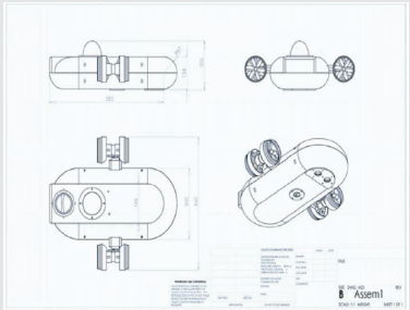
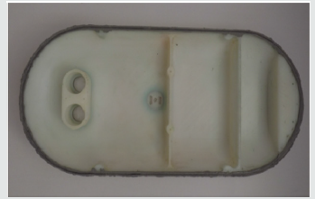
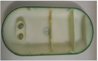
For autonomous underwater robots (AUVs) developed in research laboratories, reliable sealing remains one of the key challenges to address for successful underwater robot tests. In existing researches, most underwater robots have used a mechanical seal for water proofing. However, this kind of seal is not so consistent because of friction and wear between stationary and moving parts [1-3]. For this aim, this paper proposes a method to seal the moving parts in underwater robots, especially asymmetric robots. Some highly practical structures in AUVs are using one or two vertical fixed thrusters and some horizontal ones. However, to make it as small and light as possible, we decided to use a pair of mobile thrusters instead of vertical and fixed horizontal thrusters in order to save energy. While thrusters are fixed, all thrusters should simultaneously be on to create the desired vertical-horizontal movement, thus leading to high power consumption. To address this issue, we used two thrusters positioned in a specific angle so both vertical and horizontal forces needed to move the robot will be provided simultaneously. Varying the angle has been made possible by the instant movement of an engine stopper which consumes much less energy than the constant movement of a thruster. In the proposed AUV (Figure 1), the front part is curved while its ending part is drawn as a polygon, thus assuring less energy consumption and reducing wake effects.
The thickness of the body is 1 cm and its components are made of PTFE Teflon (Polytetrafluoroethylene) [1,4,5]. This material, widely used in industry, has some practical features such as:
a) High resistance against chemical factors
b) Resistance against adherence
c) High dielectric features (nonconductor)
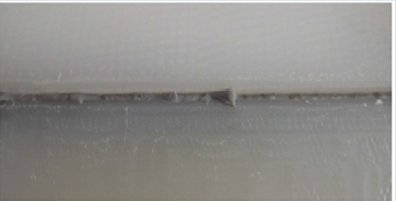
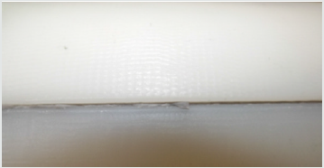
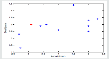
In the designed autonomous underwater robot, a groove around the body was spotted. However, after machining Teflon, the AUV body was deformed. It should be noted that deformation in machining is unavoidable, but the extent differs [4]. (Figures 2-4) show the length of the edge and the depth of the groove in 10 spots of the oval circumference of the AUV. In this design, the length of the edge and the depth of the groove were designed to be 3 mm. and 3.1 mm. respectively. In these figures, the deformations at machining have brought about significant variations in the extent of depth of the groove and length of the edge. Note that a valve was allocated to the end of the AUV in order for the middle groove to be sealed and closed only once, thus leaving the access to the internal parts via the valve. Nevertheless, the sealing should be efficient to prevent any leakage afterwards.
Figure 2: Depths of the groove in 10 spots, red spots show the design values and blue spots the measured one.
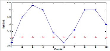
Figure 3: Length of the edge in 10 spots, red spots show the design values and blue spots the measured ones.
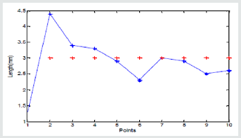
Figure 4: Ratio between length of the edge and depth of the groove in 10 spots, red spots show the design values and the blue ones the measured values; the closer to the red spot, the better the fabrication will be.
O-Ring
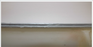
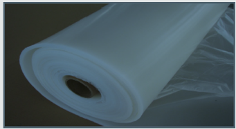
One of the most common methods for sealing AUVs is the use of O-Rings since most of them have a cylindrical shape. However, designers usually face the issue of irregular groove depth and noncontinuous edge. Furthermore, even if some methods for reducing groove depth variations and improving edge sharpness have been proposed, they are mainly based on models based on the upper edge. In such methods, silicone materials are usually poured into the middle of the groove and covered by Nylex sheets [4]. Next, the upper part of the body is placed, and the groove forms an edge. After a while, the middle material becomes dry and Nylex could be separated [1, 4]. The middle material has a complete elastic form and even can be used as O- Ring or Gasket by itself. We then tested this technique using a range of aquarium glues with various percentages and Gasket Makers (Figure 5). The Nylex sheet was not used in the aforementioned method and the edge was inserted into the basic material of silicon. However, once completed, reopening the whole system for maintenance or adjustments will be problematic and time- consuming. Also, leakage was observed even after O-Ring placement. This can happen due to two reasons,
a. The inappropriate quality of the middle material and,
b. The deformation of the horizontal shape of bodies, i.e., its twisting along length.
Gasket
Using Gasket instead can be an option where low pressures are involved (i.e., AUVs working at relatively low depths), which is the case in our application. So, Gasket was then used with sticky and elastic material placed between two sheets; then upon pressing the sheets together, they become fastened. As mentioned earlier, basic silicon materials have the features of a good Gasket (Figures 6-10).
As shown in the above figures, sealing seems to be adequate. However, further tests showed that after some body twists, another leakage was signaled.
Grease
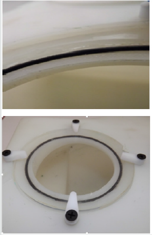
The third sealing alternative was the use of grease in the groove as a filler and insulation material (Figures 11&12). However, even if such option can be efficient, it was not considered due to possible water pollution with grease
Paraffin and Silicon-Based Materials
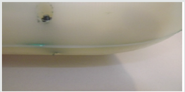
The above methods were all applied before closing the two parts of the body and practically from inside. In a fourth approach, the sealing was performed from outside. To this aim, liquid Paraffin was considered [6]. This material turns into liquid at 50-60 degrees and could be easily placed inside the groove while it sticks well to Teflon. The problem of using Paraffin is its adequate use since the existence of some tiny holes upon pouring the Paraffin can be high if the groove is relatively long, which is the case in our prototype. So this option was not retained. Instead, silicon- based materials were tested (Figure 13). Compared to Paraffin, the merit of silicon-based materials is the reduced time required to dry. Yet, a slight water infiltration was observed during tests.
Adopted Method of Body Sealing
As mentioned, the obtained sealing was secure. However, we noticed that using Butyl can raise a pollution issue because after each closing and opening, thin particles were found in the water as well as in the AUV body. To solve this problem, Butyl was replaced by Polyurethane, a material used in sealing pools and construction structures. This material exists in different forms in the market; the foam type of which was used to fill the groove between the two parts of the body, leading to appropriate sealing of the whole body.
Butyl
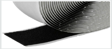
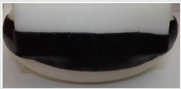
The next option was to consider Butyl (Figure 14), a polymer used in industry [7]. (Figure 15) shows the external sealing (external groove) while using Butyl along with a plastic sticky band in the form of paste, which could be easily connected and disconnected, thus not only completely solving the issue of sealing but allowing easy reopening of the AUV body for future replacement or repairs. Finally, after different tests, a proper sealing was obtained following different steps. First, the external groove was filled by a thin layer of silicon-based material. Then, the Butyl band was applied. It has to be noted that considering the nature of the Butyl tape, it can be estimated that each band of Butyl can be attached and removed for less than seven times. After that, the band should be replaced.
Sealing Access Valve
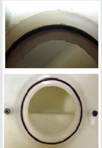
As for the other parts of the AUV like the access valve opening, O-ring was the best choice, as shown in (Figures 16&17). Note that to avoid possible leakage, O-rings with longer diameters were used. They have been filled with Polyurethane, with Teflon as ground and silicone-based material as wall.
Conclusion
In this work, different techniques to adequately seal lab submarine robots have been investigated, highlighting an ecofriendly and cost-effective approach for efficient sealing of AUVs.
References
- A Jebelli (2016) Design of an Autonomous Underwater Vehicle with Vision Capabilities. University of Ottawa Canada.
- DW Yun, K Jinho, SH Kim (2011) Study on the Waterproof Seal for Underwater Robot Using MR Fluid. Advanced Materials Research 378-379:759-762.
- DF Calafell (2010) Design and Implementation of a Modular Body for an Underwater Robot. Swiss Federal Institute of Technology Switzerland 2-95.
- VP Astakhov, S Shvets (2004) The Assessment of Plastic Deformation in Metal Cutting. Journal of Materials Processing Technology 146(2): 193-202.
- E Fischell (2008) Sealing Manual and Protocols, Cornell University Autonomous Underwater Vehicle Team.
- E Jackson (2015) The Seal Man's O-Ring Handbook, Harvard University Department of Physics.
- (2011) PTFE Seal Design Guide. Parker Hannifin Corp Belgium.

Top Editors
-

Mark E Smith
Bio chemistry
University of Texas Medical Branch, USA -

Lawrence A Presley
Department of Criminal Justice
Liberty University, USA -

Thomas W Miller
Department of Psychiatry
University of Kentucky, USA -

Gjumrakch Aliev
Department of Medicine
Gally International Biomedical Research & Consulting LLC, USA -

Christopher Bryant
Department of Urbanisation and Agricultural
Montreal university, USA -

Robert William Frare
Oral & Maxillofacial Pathology
New York University, USA -

Rudolph Modesto Navari
Gastroenterology and Hepatology
University of Alabama, UK -

Andrew Hague
Department of Medicine
Universities of Bradford, UK -

George Gregory Buttigieg
Maltese College of Obstetrics and Gynaecology, Europe -

Chen-Hsiung Yeh
Oncology
Circulogene Theranostics, England -
.png)
Emilio Bucio-Carrillo
Radiation Chemistry
National University of Mexico, USA -
.jpg)
Casey J Grenier
Analytical Chemistry
Wentworth Institute of Technology, USA -
Hany Atalah
Minimally Invasive Surgery
Mercer University school of Medicine, USA -

Abu-Hussein Muhamad
Pediatric Dentistry
University of Athens , Greece

The annual scholar awards from Lupine Publishers honor a selected number Read More...


