


Lupine Publishers Group
Lupine Publishers
ISSN: 2643-6736
Research article(ISSN: 2643-6736) 
Design, Modeling and Indigenous Firmware of Patient Assistance Flexible Robotic System-Type I: Beta Version Volume 2 - Issue 3
Received: March 05, 2020; Published: March 12, 2020
Corresponding author: Department of Atomic Energy, Division of Remote Handling and Robotics, Bhabha Atomic Research Centre & Homi Bhabha National Institute, Mumbai, India
DOI: 10.32474/ARME.2020.02.000140
Abstract
The ensemble of Assistive Robotics is slowly emerging as the new front-edge research arena due to its wide-spread applications in health care sector. Although exoskeletons are is use to a limited extent in the field of health care, it has its own limitations so far the design, prototyping & miniaturization are concerned. Patient-centric customized health care is the need of the hour and research frontiers are also getting negotiated accordingly. One such promising application manifold of Assistive Robotics is the incorporation of multi-degrees-of-freedom flexible robotic system, equipped with tailor-made mini-gripper(s). In-line with the proposition an indigenous design, modeling and firmware of Patient Assistance Robot (PAR): Type I has been accomplished by us as version 1.0 prototype (Beta version). The characteristics of PAR v1.0 are identical to that of Flexible Robotic System with multiple links & intercepting joints, besides fittment of three different miniaturized grippers. The ensemble programming logic for the robot is developed towards controlling in-built vibration in real-time.
Keywords: Flexible robot; Revolute; Assistive; Vibration; Controller; Mini gripper; Dynamics; Sensor; Instrumentation; Firmware
Introduction
The field of Flexible Robotic Systems (FRS) is one of the niche ensembles of present-day robotics research that caters for real-time aspects like rheology (stress-strain paradigms), in-situ vibration, sensor fusion & non-linear coupled dynamics for control. As some of these features are inherent in FRS, prototyping multiple degreesof- freedom semi-flexible robot as an application-centric firmware like PAR is highly challenging. This research reports the design as well as modeling issues for the firmware of higher-order FRS, as a foundation to fully-operational & commercial version of PAR: Type I. The research is focused on a novel design & prototype hardware development of PARv1.0, which is a direct manifestation of a twolink articulated-type revolute-joint semi-flexible robot fitted with miniaturized gripper(s) at the free end. We have postulated a novel application domain for this compliant flexible manipulator in health care and social sector, which is a path-shift from the traditional usability of the same in space exploration research. A revolute-jointed robot having provision for fittment of multiple grippers / end-effectors poses delicate issues in real-time control operation. Thus, the hardware of the robotic manipulator, PARv1.0 has been accomplished in a way to minimize the inherent shaking of the manipulator arms. Two posture-driven strategies have been formulated in order to combat this in-situ shaking, pertaining to two different phases of a graspable object, namely:
a. In-plane grasping.
b. Off-plane lifting.
The customized program module has been made interactive in
order to systemize multiple grippers. The attributes of parametric
design and dynamic simulation of the controller of PARv1.0 have
been reported, along with results of test-runs.
Although flexible robots have become favourable choice in
several new applications because of its slender design, light weight,
small size-envelope & increased reachability in the workspace, yet
the major bottleneck of FRS lies with the effective control of its
inherent vibration. This structure-independent inherent vibration
gets realized in form of mild to severe trembling of the slender links and/or shaking or twisting of the inter-spaced joints, no matter
what the type of FRS-hardware is. In fact, slenderness of the links
as well as design of the FRS-joints do play important role in selfgeneration
of this trembling. As observed in the FRS-hardware,
internal stress-strain and vibration (modal frequency & eigen value)
are completely built-in type and hence those are design invariant.
Several designs of FRS have been attempted by the researchers in
past decade in order to alleviate this vibration but most of those
trials have been unsuccessful. The problem gets even complicated
when we attempt for multi-link design of the FRS, wherein various
kinds of coupled effect & non-linearity crave in. It has been also
observed that vibration in FRS is not time-dependent and the
duration & periodicity of it can’t be correlated with the task-space
of the robotic system. Besides, this vibration is self-propagating
in nature as well as random and it gets induced to the successive
member of the FRS till the end-link & end-effector / gripper. So,
we must have real-time assessment of vibration signature in FRS
a-priori towards establishing a reliable application-centric control
system.
A new model on vibration-induced dynamics of the multiple
degrees-of-freedom FRS will be reported in this paper. The
vibration signature in such FRS gets assessed in real-time through
various force sensors, affixed over its links & joints in a geometrical
layout. A majority of the dynamic models used hitherto in FRS
have been found to be somewhat inappropriate for real-time
monitoring & control of the end-of-arm payload. We will discuss
on a novel dynamic model of the multi-link FRS in this paper,
referring its real-time operation. Control issues of FRS have gained
research attention over the last few decades that deal with novel
techniques on harnessing system dynamics in real-time [1]. While
perturbation method was tried for fine-tuning FRS-controller [2],
direct real-time feedback from strain gauges was experimented too
[3]. It is true that a robust dynamic model becomes very effective
in understanding the behavior of FRS in real-time and the same
becomes crucial for a multi-link FRS [4, 5]. Feliu et al attempted
the control issue of a three degrees-of-freedom FRS using the
methodology of inverse dynamics in contrast to strain gauge-based
control [6, 7]. The fuzzy learning-based approach for control of FRS
was also reported by Moudgal et al. [8]. Specific metrics related to
reduction of system vibration of a robotic gadget were attributed by
Singer & Seering [9]. Various techniques for vibration attenuation
& control in FRS have been reported hitherto, such as sliding mode
theory [10], adaptive resonant control [11], online frequency &
damping estimation [12] & integral resonant control [13]. Dynamic
model & simulation of FRS based on spring and rigid bodies was
established too [14].
It is important to comment here that laboratory-based
experimentation on the control semantics of single-link flexible
robot gained substantial leverage over the years. These flexible
arms have served as robust test-bed for various new control
strategies like load-adaptive control (using end-of-arm mass) [15,
16]; end-point control [17]; acceleration-feedback control [18] &
inversion method-based trajectory control [19]. Chronological
survey on FRS research reveals that nearly all global studies
hitherto are concentrated on various experiments on the control
synthesis of single-arm FRS with or without end-mass. Kinematic
& dynamic effect of end-of-arm tooling and/or gripper in such
FRS was also not addressed till date. However, both rheology &
vibration characteristics of FRS will drastically alter as soon as
jointed structure is in place, i.e. multi-link multi-jointed FRS with
a miniaturized gripper fitted at the open end. We have investigated
such scenarios of control dynamics for a multi-degrees-of-freedom
FRS fitted with mini-gripper [20], postulating spring-dashpot-based
model (for vibration signature) and strain gauge-induced model
(for dynamic strain signature). Design of drive & actuator system
for a test set-up of a three-link serial-chain FRS and subsequently,
realization of its firmware have been reported by the author’s group
[21, 22]. The proposition of real-time vibration signture of planr
FRS & its harnessing has been discussed thoroughly by the author
[23]. The paper has been organized in six sections. An overview
of some critical design variations & mechanical sub-assemblies of
the serial-chain FRS is presented in the next section. Details on the
sensory augmentation and modeling of the control dynamics of the
developed FRS, i.e. PAR-typeI-v1.0 have been discussed in section
3. Salient aspects of the hardware of the fabricated PAR-typeI-v1.0
is reported in section 4. Section 5 addresses the paradigms of
the control system algorithm, an overview of the FRS-controller
developed & test results. Finally, section 6 concludes the paper.
Serial-Chain Assistive Robotic Systems: Mechanical Design & Analysis
Design ensemble of serial-chain FRS, due for use as Assistive Robot, has evolved in recent past with novel research paradigms. It is crucial to note here that the vibration and/or rheological features of the FRS do alter under two situations of end-of-arm attachment, viz. end-/tip-mass vis-à-vis a mini-gripper (at the distal link of the FRS). Figure 1 schematically illustrates major design ensembles of serial-chain FRS, as per the varaition in the cross-section of the link, namely, circular, rectangular or square. These three types of possible cross-section of the FRS-links are illustrated in Figure 1 for a single-link FRS-arm, as detailed under section A-A’. Nonetheless, nomenclature will be valid for multi-link FRS too. For example, as evident in Figure 1, Cartesian co-ordinates are established at the ends of the ith. FRS-link, viz. at two joint-locations (Ji-1 & Ji), spanning a horizontal length Li & an inclination of qi (measure of flexibility). It is important to note also the numerical measure of the crosssectional area of the ith. FRS-link, Di, based on its type, viz. radius ‘r’, length ‘l’ & breadth ‘b’ tuple and side’s’, respectively for circular, rectangular & square cross-sections. It is to be noted that the most significant aspect of FRS-design pertains to the choice of drive mechanism. In the present hardware we have adopted direct-drive approach, wherein miniature servomotors were placed at the joint itself. This design is comparatively robust from the point of view of actuation of the entire system but it suffers from poor vibration control. As the system tare weight is increased due to addition of servomotors at the link-joint interface, the trembling or in-situ vibration becomes more prominent in case of direct-drive FRS. On the basis of end-application requirement, we have used direct-drive system for the FRS-hardware in this work. Figure 2 presents an ensemble schematic of the developed small-sized serial-chain PARtypeI- v1.0 hardware, having three links & three joints. In order to add generality, legends of Figure 2 have been selected so as to cater for a multi-link multi-joint serial-chain FRS too. Thus, overall span of a n-link FRS is indexed as ‘ Σ Li’, where link-lengths are denoted by ‘Li’, ∀i = 1,2,3,…,n. Likewise, the revolute joint-ensemble is indexed as {Ji, Ji+1, Ji+2,…..,Ji+n-1} when a fixed value of ‘i’ is considered (i=1). However, servomotor-ensemble is indexed as {Mi-1, Mi, Mi+1,… .,Mi+n-1}, under i=1. As illustrated in Figure 3, the drive for all three joints are direct, i.e. coupled straight away with the respective servomotors {M1, M2, M3}. The mini-gripper, G is being actuated through its dedicated servomotor, Mg, located at the backside of the gripper base-plate. The system is to be mounted on a customized mechanism beneath the base, having translational motion to position the FRS at the desired horizontal plane. The mechanism is composed of two sub-assemblies, viz, tripod stand, B1 & prismatic slide, B2, driven by motor M0. This prismatic slide is positioned on the tripod and is being actuated through re-circulating ball screwnut mechanism having linear movements along vertical Z-axis. It is to be noted that hardware manifestation of {B1, B2} tuple is very sensitive as the alignment of the prismatic slide governs the deflection of the entire FRS.
Figure 1: Schematics of the Major Design Ensemble of Serial-Chain FRS as per Cross-section of the Links.

Figure 2: Ensemble Schematic of the Developed PAR-typeI-v1.0 Hardware.
{A}i: Links; B1: Tripod stand; B2: Prismatic slide; Mi: ith Servomotor; Ji: ith Revolute joint; {C}i: Couplers of motors; {D}i: Seat for
motors; G: Mini-gripper; E: Object to be gripped; F: System controller; H: Wiring & instrumentation;{X0, Y0, Z0} & {Xi+3, Yi+3, Zi+3}:
Cartesian co-ordinate systems at base and end-effector (attachment of gripper).

Figure 3: Collage Photograph of the Prototype Patient Assistance Flexible Robot –TypeI –v1.0.
Index: [a]: FRS-base, joint 1 & a part of FRS-first link; [b]: A part of FRS-first link, joint 2 & partial view of the FRS-second link;
[c]: Partial views of FRS-second & FRS-third links & joint 3; [d]: A part of FRS-third link & mini-gripper.

Figure 4: Schematic and Layout Disposition of a Revolute Joint Assembly of PAR-typeI-v1.0.
A: Joint-body; B: Coupler; C: Gear-train; D: Servomotor; E: Actuation plane of the joint; F: Cartesian co-ordinate systems (4
nos.); G: Direction of assembly / dis-assembly of the joint; H: Motion pathway of the joint assembly.

One important paradigm of a serial-chain FRS is related to the
optimal joint design. Serial-chain FRS being planar, all joints are
ideally conceived as revolute type, with design variations in its subassemblies.
Barring minor design variations, all FRS-joints do have
rotating shaft, miniature ball bearings, end-covers & housing and
at times, a gear-train (worm-worm wheel or spur). Joint design
is correlated to the design of links too as the end-fittings of the
link(s) will be an extended part of the joint assembly. This linkjoint
mating zone is very significant in FRS, unlike usual serialchain
robotic manipulator. The labeled schematic of the revolute
joint assembly of PAR-typeI-v1.0 is shown in Figure 4, highlighting
salient dimensions of the constituent members. The disposition of
the manufacturing of the revolute joint assembly of PAR-typeI-v1.0
and the external view of an assembled joint are shown in Figures 5a
& 5b respectively. One important paradigm of a serial-chain FRS is
related to the optimal joint design. Serial-chain FRS being planar, all
joints are ideally conceived as revolute type, with design variations
in its sub-assemblies. Barring minor design variations, all FRS joints do have rotating shaft, miniature ball bearings, end-covers
& housing and at times, a gear-train (worm-worm wheel or spur).
Joint design is correlated to the design of links too as the end-fittings
of the link(s) will be an extended part of the joint assembly. This
link-joint mating zone is very significant in FRS, unlike usual serialchain
robotic manipulator. On the basis of this design framework of
the joint, we have customized the revolute joints of PARv1.0 within
an ensemble module having the joint controller board (for directdrive
system). This design of joint of PARv1.0 needs a bit extra space
around joint housing. The current version of the developed FRS, i.e.
PAR-typeI-v1.0 has got the following four sub-assemblies, viz.
a) Base.
b) Link & Joints.
c) Mini gripper.
d) Drive system & controller.
Figure 5: Revolute Joint Assembly of PAR-typeI-v1.0: [a] Manufacturing Schematic; [b] Outer Ensemble.
A: Pin; B: Micro-Bearing (Upper Rung); C: Micro-Bearing (Lower Rung); D: Joint Housing; E: Adapter Plate; F: Fixing Screws;
G: Extension Plate; 1: Lower Housing; 2: Upper Housing; 3: Access for Bearings; 4: Joint Shaft.

The base sub-assembly is a novel mechanism that has got interconnection with the first link and system controller. The prismatic movement helps the FRS to achieve the desired planar location depending on the requirement of the end-application. The link & joint sub-assembly is the backbone of the prototype as it maintains the synergy between the link, actuating joint & driving servomotor. It is to be noted that we have incorporated only the servomotor, responsible for the actuation of the specific joint in the link assembly. The driver circuitry & allied motion controller of each servomotor were augmented under a separate ensemble refer ‘F’ in Figure 2. The wiring & instrumentation, related to FRS control system is having a direct interface with the base sub-assembly refer ‘H’ in Figure 2. The present FRS-prototype has a niche in minigripper sub-assembly too. Besides size miniaturization, it has a unique design for the jaws. As seen in Figure 2, both jaws of the mini-gripper are flat plate type and are being driven by spur gears & actuated through a customized linkage on either side (fitted between the base plate & the jaw).
Sensor Augnentation and Modeling of The Control Dynamics of Patient Assistance Flexible Robot
Sensor augmentation
Chronological survey on FRS research reveals that nearly all
studies worldwide till date are concentrated on various experiments
on the control synthesis of single-arm FRS with or without end-mass.
Kinematic & dynamic effect of end-of-arm tooling and/or gripper in
such FRS was also not addressed hitherto. However, both rheology
& vibration characteristics of FRS will drastically alter as soon as
jointed structure is in place, i.e. multi-link multi-jointed FRS with
a miniaturized gripper fitted at the open end. We have investigated
such scenarios of control dynamics for a multi-degrees-of-freedom
FRS fitted with mini-gripper, postulating spring-based model (for
vibration signature) and strain gauge-induced model (for dynamic
strain signature). The real-time ensemble motion of any link of a
flexible robot is a conglomeration of two entities, namely:
a) Rigid motion (similar to Euler formulation of rigid body
dynamics).
b) Elastic motion (description of the deformation state).
While the rigid motion is characterized by the rheology of the
FRS, e.g. strain vectors of the links / joints, the elastic motion serves
as the source for the inherent vibration of the system. It is to be
noted that basic strain in PAR-typeI-v1.0-link is being measured
through multiple strain gauges, placed over the external surface of
the link(s). The paradigm of in-situ vibration of PAR-typeI-v1.0-link
can be symbolized best as the real-time deflection of a cantilever
beam, as shown in Figure 6. Cantilever-type FRS-members do
possess easy potential for affixing sensing element(s) as well as
better relief at the non-fixed end. The design of such FRS can have
one or more cantilever member, having relatively larger deflection
potential at the ‘free’ end. As illustrated in Figure 6, the PAR-typeIv1.0-
member will have mutiple strain gauges afixed, which are
representative of micro-beam. T the force sensing mechanism of
the PAR-member will be based on beam deflection principle. A
particular FRS-member may have multiple beams embedded in
it, each having its own characterization. The placement of those
beams inside the FRS-member is also another technological
challenge. Each link of the prototype PAR-typeI-v1.0 is augmented
with strain gauges & flexi-force sensors. However, due to constraint
of hardware & allied logistics, we have limited the fitment of strain
gauges. Strain gauge-type resistive sensors are the prime sources of
detection of the vibration in PAR-typeI-v1.0 in real-time, backed up
by indigenous electronic circuitry hardware.
Figure 6: Schematic Layout of the Sensor Augmentation of the Flexible Link of PAR-typeI-v1.0.
A: Flexible Link; A’: Deflected Posture of the Flexible Link; B: Support –End of the Cantilever Link; C: Rotated Posture of the
joint-Axis; {D1 to D6}: Strain Gauges; E: Actuation plane of the Flexible Link; F: Imaginary Spring Elements (symbolizing
vibration); G: Direction of assembly / dis-assembly of the Spring Members

Modeling of real-time dynamics
The flexible link of a serial-chain FRS can be concetualized as a ‘free elastic body’ in ideal scenario, but in all practical purposes we can treat it as a ‘cantilevered eastic body’, which acts as the prime source of in-situ vibration of FRS. In all practical situations of serial-chain FRS, this inherent vibration is evaluated in terms of natural frequency of vibration (wn) and the higher-order modal frequencies. The inherent vibration of FRS is directly proportional to its number of degrees-of-freedom. The study on the movement / instanataneous motion of FRS-links should ideally be restricted to low joint speeds, thereby neglecting the second-order effects of elastic deformation. In fact, in al such cases, second order & higher terms of control equation need to be avoided for successful control of FRS. On the other hand, the dynamic strain vector (ei, ∀i = 1,2,3,…,k: where ‘k’ is the link-number of FRS) is evaluated from structural analysis of the FRS. Thus, the paradigm of control dynamics of the present hardware, namely, PAR-typeI-v1.0 essentially involves investigation of strain vis-à-vis vibration tuple in real-time. In case of ‘direct-to-joint-drive’ serial-chain FRS, the instantaneous realtime displacement, in the form of ‘deflection’, will be prudent in the links. It is important to note that an efficient dynamic model of PARtypeI- v1.0 will be able to characterize deformation & deflection of its members in real-time. While PAR-typeI-v1.0-links are more prone to deflection with ceratain frequency of vibration, the joints are subjected to mild deformation. At times these two entities are quite inseparable and we need to reply on FEA simulation and trialrun of the hardware only. The ensemble deformation at the PARtypeI- v1.0-joints will be accounted as friction torque while stiffness will be estimated through viscous damping of the joints as per the equation below in support of the real-time dynamics of the FRS:
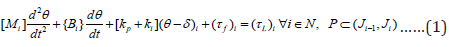
Where, i: link number; p: joint index; Ji-1 & Ji: Consecutive revolute joints; q: Rotation of the link; M: Desired moment of inertia matrix of the link; Bi:Desired viscous damping (friction) coefficient of the ith. link; Kp: Desired stiffness of the pth. joint; Ki: Desired stiffness of the ith. link; d: Initial angular position of the link and/or joint; tf: Frictional torque; tL: Load torque; N: Real numbers. It may be observed that the proposed dynamic model of the FRS, as per equation. 1, is essentially torque-induced material equation, wherein selection of appropraite material for the links as well as the joints is very crucial. The terms of the dynamic model equation include vectors of angular velocity & angular acceleration that need to be determined through real-time experiments. Several designs of FRS have been attempted by the researchers in past decade in order to alleviate the inherent vibration but most of those trials have been unsuccessful. The problem gets complicated when we attempt for multi-link design of the FRS, wherein various kinds of coupled effect & non-linearity crave in. It has been also observed that vibration in FRS is not time-dependent and the duration & periodicity of it can’t be correlated with the task-space of the robotic system. Moreover, by nature, this vibration is self-propagating and random and it gets induced to the successive member of the FRS till the end-link as well as the end-effector / gripper. With lal these factors in mind, the real-time assessment of vibration signature in FRS is a prerequisite for establishing a reliable control system for any real-life application, such as in the present case of PAR-typeI-v1.0.
Fabrication of Prototype Patient Assistance Flexible Robotic System: Salient Aspects
Major paradigms of the prototype (Beta Version)
The working prototype of the PAR-typeI-v1.0 was fabricared
indigenously, equipped with three nos. revolute joint-actuated
links of unequal length but uniform cross-section and one no.
miniaturized gripper at the distal end. All revolute joints are
actuated through D.C. servomotors (Make: Faulhaber™), integrated
with gear-box & encoder. The patient assistance flexible robot is
equipped with several limit switches for each servomotor in both
directions so as to invoke precautionary measure for overrun of
the rotary motions. The fabrication of the prototype was realized
through five sub-assemblies, namely:
a) Fittment of the First Link & Base Sub-assembly.
b) Second & Third Link Sub-assembly.
c) Joint Sub-assemblies.
d) Gripper Sub-assembly.
e) Tripod Sub-assembly.
It may be stated here that it was not possible to initiate entire
manufacturing of PAR-typeI-v1.0 in one shot due to its long &
slender disposition, piggy-backed with testing of motor controllers
& strain gauge-based instrumentation. This piece-meal testing of
the joint controller, sensory instrumentation & gripper operation
gave an edge over the final assembly of the FRS towards full proofing
the same. With reference to Figure 2, it may be noted that except the
base (tripod) sub-assembly, all other components & sub-assemblies
are mostly hand-made. This is an unique feature of our prototype,
especialy for the miniaturized gripper. Another salient aspect of
the prototype is its sleek wiring & cable-routing. Figure 3 shows
the partial photographic view of the developed three-link serialchain
direct-drive flexible robot, PAR-typeI-v1.0 (beta version)
with the mini-gripper, in a thematically assembled disposition (two
parts, viz. [I] & [II]: second & third links and mini-gripper:: to be
seen from left to right). The relocation of the prototype FRS, postcommissioning,
is not trivial as the assembly of the flexible robot
needs to be compacted under 3 to 4 functional sub-assemblies, as
indicated in Figures 3 & 7. While the collage photographic view of
the developed three-link serial-chain ‘direct-drive’ flexible robot
with miniaturized gripper is illustrated in Figure 3, the details of
the sub-assemblies of PAR-typeI-v1.0 are viewable in Figure 7.
Figure 7: Photographic View of the Fabricated Patient Assistance Flexible Robot –TypeI –v1.0 (Link2, Link3 & Mini-Gripper). A: Second Link (Link 2); B: Third Link (Link 3); C: Joint 3; D: Mini-Gripper; E: Joint Motor Controller; F: Gripper Motor Controller

Crucial sub-assembles
Our development of PAR-typeI-v1.0 is intended for use in hospitals, health care establishments and allied medical day-care units. The prime attention is paid to the mini-gripper of PAR so that it can grip items likes medicine strip, pill, syringe, cotton, tape, adhesive, glue-stick, plastic spoon, plastic fork, scalpel, plastic knife, paper cup, paper saucer, small plastic bottle etc. and bring those things before the patient / care-giver. The majority of these operations are of ‘pick-and-place’ type but the challenge is to control the gripper motion amidst the flexibility of the ensemble. The slenderness of PAR-typeI-v1.0 and its low tare weight provide serious bottlenecks on designing the control system. Thus, the deployment of PAR becomes quite challenging. A successful deployment of this prototype asof now is entrusted to reduce the burden on the hospital staffs and help in creating a tension free environment. Besides, patients, admitted in the ICU, will be able to do some tasks of their own without any intervention from anyone aided by this robot. Augmentation of sensors at PAR-gripper do play a significant role in overall performance of the prototype. While rheological data pertaining to strain & vibration of the PARlinks & joints have been captured by the semiconductor-type strain gauges, the instrumentation at the mini-gripper is attributed to flexi-force sensor, mini-load cell & infra-red sensors. Figure 8 shows the photographic view of the fixation and instrumentation of flexiforce sensors on the mini-gripper of PAR-typeI-v1.0.
Figure 8: Details of the Sensory Instrumentation of the Miniaturiuzed Gripper of PAR-typeI-v1.0.
A: Flexi-force Sensors; B: Jaw-plates of the Mini-Gripper; C: End-Connectors of ‘A’; D: Multi-wire Cable for Sensors; E: Servo-
Control Board of Gripper Motor; F: Location of Load Cell & Infra-red Sensors.

The long & slender flexi-force sensors are mounted on the jawplates of the gripper, fitted with a sleek connector (refer ‘C’), which is finally connected to the multi-wire cable for sensors (refer ‘D’). The servo-control board for the gripper motor is mousnted on the flange part of the gripper body in order to reduce wiring as well as trembling of the gripper-body. The hardware augmentation of flexiforce sensors becomes critical predominantly due to the length, which becomes a constant souce of jitter for the ensemble minigripper. The fittment of the infra-red sensors (as emitter & detector pair on both jaw-plates) is also challenging because of the tiny sizes and the space available for fixation (refer ‘F’). Both the fittments were skill-based and carried out manually under extreme care. In contrary, fixation of strain gauges was relatively easier, although the tiny sizes did cause bottlenecks, throughout the assembly sequences of PAR-links.
Control System Hardware of The Patient Assistance Flexible Robotic System & Test Results
Description of the system controller of PAR
The backbone of the control system algorithm of the fabricated PAR-typeI-v1.0 is Proportional-Integral-Derivative (PID) control, augmented by a novel vibration (frequency) attenuation module. The overall control system facet has been tuned with currentbased cut-offs and electronic limit switches to arrest joint overrun. The servo-based control of the PAR-joints as well as PAR-gripper has been effected with individual user-selective feedback gain amplifier(s). It is to be noted that the control system architecture of the prototype is composed of four distinct but similar PID loops, each one of that is responsible for the three joints of the PAR and the mini-gripper. The set-values of the joint-angles of the three revolte joints of the PAR play important role in tuning the PID control-blocks thereafter. These set-values are assignerd a-priori through the dedicated servo-controllers (Make: Faulhaber®) of the corresponding servomotors of the joints. The program-code, generated for the PAR, includes these set-values and these values can be re-set depending upon the need of the end-use. Similar to the selection of set-value triad of the joint-angles, the servomotor, responsible for the actuation of the mini-gripper of the PAR is also gets tuned by seting the rotary motion of the motor-shaft of the PAR-gripper. Hence, the ensemble set-value of the PAR becomes the maiden input to the system controller and its matching programcode. The system controller is provided with easy switch-over from electrical to battery-based activation of the PAR-typeI-v1.0 under indoor condition, in case the situation demands so. Precaution should be adhered to for outdoor applications, as factors like heavy rainfall, direct sunlight, dust, excessive water sippage or similar such exposure to water can cause damage to the units of the controller box. The control system program code has been syntaxed so as to give priority towards functioning of the limit switches. The program code inducts binary output of the limit switches and ensures complete stopping of the servomotor(s). All four motor controllers of the prototype PAR-typeI-v1.0 were interfaced with serial RS232C port of the system comuputer for seamless data communication in easy way. It may be noted that the basic logic of functioning of all Faulhaber™ motor controllers is same despite different models of Faulhaber™ motors are used in the hardware. The Faulhaber™-Motion Manager software has been instrumental in controlling the overall functioning of all four servomotors of the FRS and the motor for tripod movement. The indigenously developed control system program has got good handshaking with Faulhaber™-Motion Manager software, as the later has userselectable drop-down menus for the desired control parameter.
Experimentation with the prototype PAR and results
The prototype PAR-typeI-v1.0 was critically examined for its
performance in real-time through different sets of trials & testings.
These tests are beyond usual calibration of the sensors, which are
aimed towards assessment of the real-time characteristics of the
FRS. The two most significant as well as salient aspects of this realtime
performance are
a) Evaluation of the ensemble sstrain in the PAR-links &
PAR-gripper.
b) Determination of natural frequency of vibration of the
PAR-typeI-v1.0.
Real-time data from the strain gauges, mounted over the
exterior of the PAR-links, symbolized the out-of-balance voltage
of the respective Wheatstone bridge circuitries of the strain
gauges. These voltage values were further deduced to evaluate the
final data for strain in the PAR-member. In order to attatin better
accuracy of the experimental results, each strain gauige was put
in the instrumentation as a single entity and the corresponding
Wheatstone bridge was made as quarter-bridge. A total of 10 strain
gauges were fixed on all three links of the PAR, out of which six
were mounted on the first link (length: 800 mm.) and two each on
the second link (length: 400 mm.) and third link (length: 200 mm.)
respectively. These 10 strain gauges have separate quarter-bridge
instrumentation that were augmented under ‘Sensor Processing
Module’ of the PAR-controller. Likewise, the mini-gripper of the
PAR is provoded with 2 nos. flexi-force sensors, having in-built
Wheatstine bridge circuitry. The raw data output of these two
flexi-force sensors in miili-volts were processed separately to get
the strain values, using calibration curve of said sensor. Table 1
presents the ensemble dynamic strain values of 2 nos. strain gauges
on the distal link of PAR and 2 nos. flexi-force sensors respectively,
as obtained during various time-intervals under different trialruns.
Dynamic strain values were computed from the raw data of
the strain gauges. These sensor units have been nomenclated as
S1, S2, S3 & S4 in a sequential manner (starting from Link3 and
ending with mini-gripper). We have computed the average values
of strain too, as shown in the Table 2. All of these 12 trials have
been time-synchronized, i.e. these trials have been undertaken
chronologically. The raw data of the strain gaues have been
generated through qualitative forcing at the tip of the distant link as
well as at the gripper-end, excuted manually. The forcing function is
essentially touch type with a mild jerk during later part of the trials.
Table 1: Test Results on the Computation of Dynamic Strain for the Distal Link & Gripper of PAR-typeI-v1.0.

[ Θ : Actual Experimental Data =Tabulated Data x 10-5]
Table 2: Evaluation of Natural Frequency of Vibration for the Distal Link of the PAR-typeI-v1.0.

(Excitation via First Joint –Servomotor)
We will now examine the computed data on natural frequency of vibration (in Hz.), as obtained through several trials on the prototype PAR-typeI-v1.0. Although various links of the PAR as well as PAR-gripper will have marginally different values of the natural frequencies of vibration under free-form undamped motion, for the sake of ensemble analysis we will consider here the vibrational frequency at the distal part of the PAR, viz. at the tip of the third link. It is true that under natural condition of joint rotations of the PAR, there will be built-in oscillations in all three links of the PAR as well as PAR-gripper. These oscillations and ensemble trembling of the PAR-links are not coupled all the time and due to this, we get different deflection hues for the links. There are various pathways to study the patterns of deflection hues and subsequent oscillations of the PAR-links, which get translated to robust analyrical models fior evaluating vibration-related parameters of the PAR under real-time dynamics. In its simplest form, we will consider here undamped free vibration of the PAR-links, without any external forcing. Numerical evaluation of natural frequency of vibration is traditional theory-based and for a specific material & known mass of PAR-link, it is directly proportional to the spring constant or ‘Keq.’, depending upon the layout schemata. Interestingly, ‘K’ is also dependent on geomtetry of the PAR-link as well as its material. In a way we get a tuple to evalauate natural frequency of vibration, fn, of the PAR-link system, as shown below:
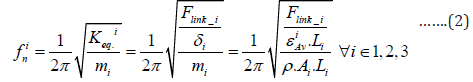
where, mi: mass of the ith. PAR-link; Flink_i: in-built force acting
on the ith. link to cause vibration; A: cross-sectional area of the link;
L: length of the link; eAvi: Average strain obtained at the ith. link of
the PAR; di: deflection of the ith.. link (in the direction of in-built
forcing function); r : density of the material of fabrication of the
PAR-typeI-v1.0; Ai: Cross-sectional area of the ith. link of the PAR.
It is intertesting to note that equation 2 can be recast in a way
so as to fit the real-time data, pertainig to run-time torque of the joint servomotor of PAR. For example, if PAR-typeI-v1.0 is excited
by the jth. joint-servomotor, then the working formula for ‘fn’ will be
as follows:
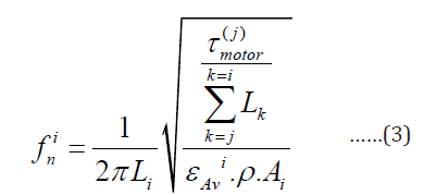
where, tmotor(j): Run-time torque of the jth. servo-motor of the
PAR-typeI-v1.0 (∀j = 1,2,3).
In our case-study, we will register experimental data with
respect to the activation of the first joint-servomotor of the PARtypeI-
v1.0 and we will investuigarte the efrect of such excitation
on the third link of the PAR Table 2 presents the experimental
data against10 trial-runs and also the computed values of the
natural frequencies of vibration for the distal /third link of the
PAR, while activated by the first joint-servomotor. The results have
been arrived at by using the formula of equation 3. The real-time
dynamics of PAR-typeI-v1.0 has a strong dependence on the builtin
vibration and its incarnations. The inherent vibration of the
flexible robot is directly proportional to the number of degreesof-
freedom and finally, on the numerical estimate of the natural
frequency of vibration, as can be observed from the data of Table
2. The paradigm of control dynamics of PAR in real-time essentially
involves investigation of strain vis-à-vis vibration tuple. In case of
‘direct-to-joint-drive’ serial-chain FRS, the instantaneous real-time
displacement, in the form of ‘deflection’, will be prudent in the links.
Nonetheless, the dynamic control of PAR-typeI-v1.0 is essentially
data-driven and postulation-based, as generated from the damping
model.
Conclusion
The indigenous hardware of a prototype serial-chain three-link flexible robotic system, namely, PAR-typeI-v1.0 has been reported in the paper. A new model for in-situ vibration signature of a multilink flexible robotic system using spring-model and strain gauges is also delineated. The system dynamics of multi-link FRS, such as PAR-typeI-v1.0 is quite different from that of single link flexible robots due to the coupling effects of joints and its drive-train, alongwith run-time program. Scientifically ascertained locations of augmentation of strain gauges on the PAR-links play a crucial role too in the overall target of achieving smoother control of the system dynamics. The present research builds up an optimal foundation for analyzing inherent vibration of flexible robots and its performance in gripping small payload in real-time. The ideation will be instrumental in creating novel designs for similar such FRS with sensory instrumentation. Although flexible robots have become favourable choice in several new applications because of slender design, light weight, small size-envelope & increased reachability in the workspace, yet the major bottleneck of the system lies with the effective control of inherent vibration. Thus, real-time modeling and hardware manifestation of PAR-typeI-v1.0 is domain worthy of modern robotics research. Such development attains enhanced significance when indigenous design modules for multi-link FRS having multiple degrees-of-freedom get realized. The facets of rheology, in-situ vibration, sensor layout and non-linear coupled dynamics are much interlinked in the extended envelope of flexible robot research. Characterization and semantics of all these aspects for real-time control of FRS is a challenging arena as the system is gaining foothold for a variety of applications in patient assistance as well as healthcare. Future versions of Patient Assistance Robot will usher in a new horizon of applications in the domain of Assistive Robotics, with many more challenges in task-handling by custommade miniaturized grippers.
Acknowledgement
Author acknowledges the help rendered by Shri Uday Phalnikar, Ex-Prolific Systems & Technologies Pvt. Ltd., Thane, India in assisting the hand-made sub-assemblies of the links & gripper of the prototype PAR-typeI-v1.0. The technical assistance provided by the engineers of M/s Devendra Fabricators, Nashik, Maharashtra, India is duly acknowledged pertaining to the fabrication of the prototype flexible robotic systems.
References
- Benosman M, Vey G (2004) Control of Flexible Manipulators: A Survey.Robotica 22(5):533-545.
- Fraser AR, Daniel RW (1991) Perturbation Techniques for Flexible Manipulators. NorwellMAKluwer.
- Luo ZH (1993) Direct Strain Feedback Control of a Flexible Robot Arm: New Theoretical & Experimental Results. IEEE Transactions on Automatic Control 38(11):1610-1622.
- Wen Chen (2001) Dynamic Modeling of Multi-link Flexible Robotic Manipulators. Computers & Structures79(2):183-195.
- Feliu V, Somolinos JA, Garcia A (2003) Inverse Dynamics based Control System for a Three Degrees-of-freedom Flexible Arms. IEEE Transactions on Robotics & Automation19(6):1007-1014.
- Feliu V, Ramos F (2005) Strain Gauge based Control of Single-Link Flexible Very Light Weight Robots Robust to Payload Changes. Mechatronics15(5):547-571.
- Subudhi B, Morris AS (2002) Dynamic Modeling, Simulation and Control of a Manipulator with Flexible Links & Joints. Robotics and Autonomous Systems 41(4): 257-270.
- Moudgal VG, Kwong WA, Passino KM, Yurkovich S (1995) Fuzzy Learning Control for a Flexible-link Robot. IEEE Transactions on Fuzzy Systems3(2):199-210.
- Singer NC, Seering WC, (1990) Preshaping Command Inputs to Reduce System Vibration. Journal of Dynamic Systems, Measurement & Control- Transactions of the ASME112:76-82.
- Chen YP, Hsu HT (2001) Regulation & Vibration Control of an FEM-based Single-link Flexible Arm using Sliding-mode Theory. Journal of Vibration Control7(5):741-752.
- Tjahyadi H, Sammut K (2006) Multi-mode Vibration Control of a Flexible Cantilever Beam using Adaptive Resonant Control. Smart Materials and Structures15(2):270-278.
- Juan R Trapero-Arenas, Mamadou Mboup, Emiliano Pereira-Gonalez, Vicente Feliu (2008) Online Frequency and Damping Estimation in a Single-Link Flexible Manipulator based on Algebraic Identification. Proceedings of the 16th. Mediterranean Conference on Control & Automation (IEEE)pp. 338-343.
- Emiliano Pereirea, Summet Sunil Aphale, Vicente Feliu,Moheimani SOR (2011) Integral Resonant Control for Vibration Damping and Precise Tip-positioning of a Single-link Flexible Manipulator. IEEE/ ASME Transactions on Mechatronics16(2):232-240.
- Jianhua Zhang, Ying Tian, Minglu Zhang (2014) Dynamic Model and Simulation of Flexible Manipulator based on Spring & Rigid Bodies. Proceedings of the 2014 IEEE International Conference on Robotics & Biomimetics (ROBIO-2014)pp. 2460-2464.
- Feliu J,Feliu V, Cerrada C (1999) Load Adaptive Control of Single-link Flexible Arms Based on a New Modeling Technique. IEEE Transactions of Robotics & Automation15(5):793-804.
- Yang TC,Yang JCS, Kudva P (1992) Load Adaptive Control of a Single-link Flexible Manipulator. IEEE Transactions on Systems, Man &Cybernatics22(1): 85-91.
- Canon RH, Schmitz E (1984) Initial Experiments on the End-point Control of a Flexible Robot. The International Journal of Robotics Research3(3):62-75.
- Kotnick T, Yurkovich S, Ozguner U (1998) Acceleration Feedback Control for a Flexible Manipulator Arm. Journal of Robotic Systems5(3):181-196.
- De Luca A, Lucibello P, Ulivi G (1989) Inversion Techniques of Trajectory Control of Flexible Robot-arms. Journal of Robotic Systems6(4):325-344.
- Roy Debanik (2018) Control of Inherent Vibration of Flexible Robotic Systems and Associated Dynamics. Invited Paper: Proceedings of the 8th. National Conference on Wave Mechanics and Vibrations (“WMVC-2018”), Rourkela, “Lecture Notes in MechancalEnginering”ISBN: 978-981-15-0286: ISBN 978-981-15-0287-3(eBook), Springer Book,India 201-222.
- Warude P, Patel M, PanditP, PatilV, Pawar H, et al (2018) On the Design and Vibration Analysis of a Three-Link Flexible Robot Interfaced with a Mini-Gripper. Proceedings of the 8th. National Conference on Wave Mechanics and Vibrations (“WMVC-2018”) Rourkela,“Lecture Notes in MechancalEnginering”Springer Book, India 29-46.
- Rauniyar A, Pandit P, AtpadkarV, Roy D (2018) Design Model for the Drive and Actuator of the Test Set-up of a Novel Flexible Robotic System. Proceedings of the 2018 IEEE International Conference on Computational Intelligence and Computing Research(“IEEE ICCIC 2018”), Indiapp. 15-21.
- RoyDebanik (2019) Towards the Control of Inherent Vibration of Flexible Robotic systems and Associated Dynamics: New Proposition and Model. International Journal of Robotics Research, Applications and Automation1(1):6-17.


-

Mark E Smith
Bio chemistry
University of Texas Medical Branch, USA -

Lawrence A Presley
Department of Criminal Justice
Liberty University, USA -

Thomas W Miller
Department of Psychiatry
University of Kentucky, USA -

Gjumrakch Aliev
Department of Medicine
Gally International Biomedical Research & Consulting LLC, USA -

Christopher Bryant
Department of Urbanisation and Agricultural
Montreal university, USA -

Robert William Frare
Oral & Maxillofacial Pathology
New York University, USA -

Rudolph Modesto Navari
Gastroenterology and Hepatology
University of Alabama, UK -

Andrew Hague
Department of Medicine
Universities of Bradford, UK -

George Gregory Buttigieg
Maltese College of Obstetrics and Gynaecology, Europe -

Chen-Hsiung Yeh
Oncology
Circulogene Theranostics, England -
.png)
Emilio Bucio-Carrillo
Radiation Chemistry
National University of Mexico, USA -
.jpg)
Casey J Grenier
Analytical Chemistry
Wentworth Institute of Technology, USA -

Hany Atalah
Minimally Invasive Surgery
Mercer University school of Medicine, USA -

Abu-Hussein Muhamad
Pediatric Dentistry
University of Athens , Greece
