Lupine Publishers Group
Lupine Publishers
Menu
ISSN: 2643-6736
Research Article(ISSN: 2643-6736) 
A Low Cost Prototypal Robotic Platform for Underwater Survey in Shallow Water Volume 2 - Issue 5
Conte G*, Scaradozzi D and Ciuccoli N
- Dipartimento di Ingegneria dell’Informazione, Università Politecnica delle Marche, Italy
Received: November 12, 2020; Published: November 30, 2020
Corresponding author: G Conte, Dipartimento di Ingegneria dell’Informazione, Università Politecnica delle Marche, 60131 Ancona,
DOI: 10.32474/ARME.2020.02.000150
Abstract
A small, innovative robotic platform for underwater surveys in shallow water is proposed. The platform integrates a commercially available, remotely operated, underwater micro vehicle and a specifically designed and constructed actuated buoy. The mechatronic structure and the control architecture of the platform are described together with its functional features. Tests to validate the implemented constructive solutions are briefly reported, together with functional tests to assess usability in geolocalizing underwater targets.
Keywords: Marine robotics; Remotely operated vehicles; Autonomous surface vehicles
Introduction
Remotely operated underwater vehicles or ROV are a
fundamental tool for inspecting underwater structures in e.g.
harbour areas, rivers, natural and artificial lakes. Integration
of an ROV with a surface autonomous vehicle or ASV, which
acts as a bridge for communication with a remote station, can
significantly increase autonomy, versatility and efficiency [1,2].
The idea of coupling cooperating autonomous surface vehicles and
unmanned underwater vehicles (UUV) in hybrid robotic platforms
has been considered in previous papers. In [3-5], an ASV and an
autonomous underwater vehicle (AUV) are deployed and managed
independently and cooperation consists in communicating through
an acoustic link to exchange information and commands. In such
way, the ASV can serve as acoustic relay between the AUV and a
supply vessel. Another example is provided by [6], where an ASV
is used to carry and deploy a AUV in mine counter-measures
applicative scenario. A robotic platform consisting of an ASV that
is capable of deploying and recovering an ROV has been first
considered in [7] and more recently in [9-11]. From a commercial
point of view, L3 Technologies recently presented the C-Worker 7
system that has the above mentioned characteristics [12].
Although potentially capable of performing well in a number
of tasks, robotic platforms that couple in their mechatronic and
functional structure surface and underwater vehicles may be
costly, complex to operate and logistically demanding. In this
paper, we describe the development of a small prototypal hybrid
robotic platform that overcomes these limiting characteristics. The
platform integrates an actuated buoy, as surface component, and
a micro-ROV, as underwater component. The bouy and the micro-
ROV are connected by an umbilical and the platform is linked to a
shore control station by a wireless connection.
Construction costs are low and the platform can be operated
efficiently in a very simple way by a single operator. Basically, the
operator guides the ROV from the shore control station by means of
a dedicated Graphical User Interface (GUI), using visual data from an
on-board camera and navigation data from on-board instruments.
At the same time, the buoy autonomously follows the (projection on
the water surface of the position of the) ROV, so to keep the relative
distance within a given threshold as long as the ROV maintains a
given depth. The development of the prototype has been carried
on mainly to prove the underlying concept. Therefore, some of the
solutions that have been implemented have been chosen especially
for their simplicity and low cost, without trying to optimize general
performances. For the same reason, experiments and validations
have been done by reproducing the conditions of a survey mission in a controlled environment. A future phase of work will follow in
order to construct an advanced version of the platform that can
undergo more demanding field tests.
The paper is organized as follows. In Section 2, the general
mechatronic structure of the robotic platform is described. The
underwater component is a commercially available micro-ROV,
while the surface component is an actuated buoy that has been
designed and constructed for this specific application. The buoy
structure is illustrated in details, together with the functionalities
of the overall platform. Section 3 describes the Graphical User
Interface that is used to operate the platform. Section 4 briefly
describes the tests that have been carried on to assess viability and
practical implementability of the proposed solutions. In addition,
the possibility to employ the platform in geolocalizing underwater
targets has been evaluated by performing a series of tests in a
controlled environment. Finally, Section 5 contains conclusions
and a brief illustration of future developments. The same robotic
platform is also considered and briefly described in [13], where the
focus is on the development of a 4G connection that enables the
platform to operate in harbour and coastal area under the coverage
of the 4G mobile network.
Mechatronic Structure
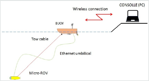
The general mechatronic structure of the robotic platform at issue is described in Figure 1. Its main components are a micro- ROV, an actuated buoy and a control console. The micro-ROV and the buoy are connected by an umbilical for exchanging data and commands and by a tow cable. The bouy and the control console are linked by a wireless connection for exchanging data and commands and for making possible to operate the platform from the shore. The control console consists of a PC, possibly equipped with a joystick, with a Graphical User Interface (GUI).
The micro-ROV
The underwater component of the robotic platform is a micro-
ROV that is remotely operated through the control console from
the shore control station. It is equipped with on-board batteries,
so to avoid the need of supplying power through the umbilical.
This feature has the advantage of making possible the use of a
thin umbilical for data and commands exchange, which minimally
affects the maneuverability of the platform. The main task of the
micro-ROV is that of carrying a video camera for visual inspection
of underwater structures. The video stream is transferred through
the umbilical and the wireless connection from the micro-ROV, to
the buoy and then to the console. It can be displayed on the PC
monitor for guidance and on-line inspection by the operator, as well
as recorded for possible off-line processing [14]. Further data from
navigation sensors are transmitted in the same way. Commands for
the vehicle’s thrusters are generated through the console by means
of the GUI using the PC mouse or a joystick and transmitted via
the wireless communication link and the umbilical. In assembling
the prototypal robotic platform, we used the micro-ROV provided
with the OpenROV v2.8 KIT [15]. The vehicle has two horizontal
thrusters and one vertical thruster that actuate three degrees of
freedom (surge, heave and yaw). Its dimensions are about 30cm x
20cm x 15cm; in standard configuration it weighs about 2.6kg in air
and it is slightly positive buoyant in water; its depth rating is 100m
and its maximum forward speed is 2kn. It is endowed with IMU,
depth sensor and an HD Video Camera, whose mounting allows tilt
movements within +/- 60 degrees from the horizontal position. The
electrical motors of the thrusters are driven by an internal control
board that generates the required PWM signals. The control board
has a built-in, static IP address that is used for connecting the
control console with it. The nominal battery life, using rechargeable
lithium batteries, is about 150min.
In addition to the sensors included in the OpenROV v2.8 KIT, a
simple sensor has been installed inside the case that contains the control board to detect possible water infiltrations. As the control
board integrates in its structure an Arduino Mega board, this water
detector consists of a commercially available Arduino shield. The
internal control board is coupled with an Ethernet switch Tenda
P200 and it is connected through an Ethernet umbilical to top-side
communication box, that integrates the Topside OpenROV Interface
Board supplied with the OpenROV v2.8 KIT and another Ethernet
switch. The Topside communication box can be linked to the control
consolle by a wired or, as in the present case, wireless connection.
Note that the choice of the micro-ROV OpenROV in ths phase of
development of the platform has been mainly dictated by the
decision to limit costs and speed up construction. Any other battery
operated micro-ROV can be used, provided Ethernet connection
with its internal control board is possible. If this is not the case, also
the umbilical can be changed in order to assure communication
with a different protocol.
The bouy
The surface component of the robotic platform is a small
cylindrical, actuated buoy that consists of a PVC tube with a sealed
endcap at one side and a removable one at the other, with a length
of 60cm and a diameter of 12cm. The buoy is equipped with two
battery operated horizontal thrusters (Turnigy DST-1200 Brushless
Outrunner motors with three-blade propeller) at one end (stern)
that actuate two degrees of freedom (surge and yaw). The main task
of the buoy is that of acting as a bridge for communication between
the micro-ROV, to which it is linked by the umbilical, and the control
consolle, to which it is linked by a wireless communication link.
Moreover, the bouy can tow the micro-ROV between the launching/
recovery position and the working area(s) where the inspection
must be conducted. The control system of the bouy is based on an
Arduino UNO board. The board drives the electrical motors of the
thrusters by generating a PWM signals for the dedicated Electronic
Speed Controllers (ESC). The bouy can operate either in the Remote
Guidance Mode or in the Automatic Guidance Mode and the
operator can command the switching from one mode to the other
at any time from the consolle. In the Remotely Guidance Mode,
commands are generated by the operator through the consolle
using the PC mouse or a joystick and transmitted to Arduino UNO
via the wireless communication link.
In the Automatic Guidance Mode, remote guidance is disabled
and the thruster are activated, under specific circumstances, by the
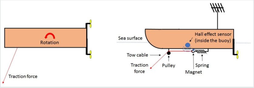
traction of a tow cable that connects the bouy to the micro-ROV. The
presence of a tow cable is necessary to keep the distance between
the micro-ROV and the bouy smaller than the length of the umbilical,
so to avoid stressing it. Moreover, its arrangement forces the buoy
to move autonomously toward the (projection onto the sea surface
of the) position of the micro-ROV when a traction force is exerted,
so that the micro-ROV is not required to tow the buoy when it is
moving. This is obtained by letting the cable pass through a small
pulley that is mounted at one end (bow) of the buoy. The shape of
the bouy facilitate the rotation around a vertical axis when traction
is exerted by the cable, so that the buoy orients its longitudinal
axis towards the (projection onto the sea surface of the) position
of the micro-ROV. One end of the tow cable is attached to a spring
that elongates due to the traction and elongation is detected by
a linear Hall effect sensor (Honeywell SS49E), placed inside the
bouy, that reacts to the position of a small magnet attached at the
spring’s end. When the micro-ROV, responding to the operator’s
commands, moves away from the buoy, the traction of the tow cable
increases. This causes first the bouy to rotate until it points towards
the (projection onto the sea surface of the) position of the micro-
ROV and then the spring to elongate. In turn, the displacement of
the magnet causes the output of the Hall effect sensor to increase.
Arduino UNO processes the sensor’s signal by comparing it with
a given threshold and, if this is exceeded, it activates, for a fixed
duration, the thrusters, moving the buoy in the surge direction. In
this way, the bouy keeps autonomously in the vicinity of the micro-
ROV, at a maximal distance that depends on the length of the tow
cable and the depth at which the micro-ROV is moving (Figure 2).
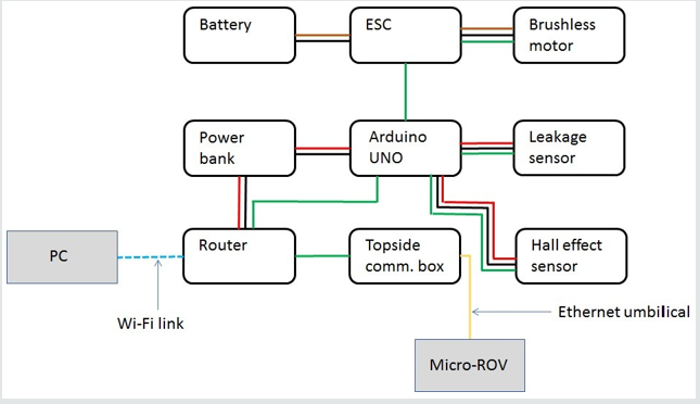
The operator at the consolle can therefore guide freely the micro-ROV, so to comply with the specifications and requirements of the inspection task, without the need of coordinating the behaviour of the bouy. The buoy is internally equipped with three water level sensors (located in the front, middle and rear section of the hull), that are commercially available as shields for Arduino UNO, to detect possible water infiltration through the endcaps. The scheme of Figure 3 shows the devices that form the functional architecture of the buoy and how they are linked. Only one ESC and motor, instead of two, is represented and only one water sensor, instead of three, is represented. Power is supplied by a 12V battery to the ESC/brushless motor and by a 5V power bank to Arduino UNO and to the communication system. Wi-Fi technology has been chosen for wireless communication between the bouy and the shore station by activating a LAN called Bouy WiFi and creating a hotspot by means of a Wlan Router Konig. This choice is clearly not valid for operations in a real word scenario, due to the limited range of Wi-Fi communication, but it is the less expensive and easiest one to implement for testing the functionality of the prototypal platform. A radio data link with a suitable transmission protocol can be used instead, while it is possible to employ the 4G or 5G network for operations in covered areas. The development and testing of a 4G connection for the buoy is described in [13]. Ethernet communication protocol has been chosen for wired transmission between the buoy and the micro- ROV. The Topside communication box in Figure 3 contains the OpenROV Topside Interface Board (which is part of the OpenROV v2.8 KIT) and an Ethernet switch (Tenda P200 Ethernet Board). The router and the Topside communication box are connected through an RJ-45 interface. Using the GUI, the operator can send commands to the control board of the micro-ROV and he can receive the video stream and the data coming from the on-board camera and the navigation sensors through the Wi-Fi/RJ-45/Ethernet link. Similarly, the operator can send commands to the Arduino UNO board that control the buoy and he can receive data from the on-board sensors through the Wi-Fi link. The bouy can be equipped with additional navigation sensors that can help the operator in guiding it and in monitoring its behaviour when it acts autonomously. In particular, the sensory apparatus can be expanded by installing an IMU, a compass and a GPS receiver. Arduino UNO is capable to acquire the additional sensory signals that can then be transmitted to the shore station to be processed and displayed on the GUI. To this aim, the simple GUI that is described later on needs to be enhanced, following, for instance, the model of the GUI developed in [2] for an autonomous surface vehicle. By processing in real-time the GPS signal, the position of the buoy can be shown to the operator on a Google map [2], providing, in that way, also indication of the area in which the micro-ROV is working. Installation of video cameras on the buoy is possible, but they would have a limited field of vision due to proximity to the sea surface. In case, the wireless communication channel should be configured in such a way to allow simultaneous transmission of more than one video stream or switching between them. It can also be interesting the equip the bouy with other sensors for evaluating physical parameters, e.g. related to water quality, that can be useful for the inspection activity. Data of this kind could be recorded and then processed off-line, without need of being transmitted through the wireless communication channel.
Control Consolle/Graphical User Interface
The Graphical User Interface runs on a PC that is connected to
the Wi-Fi LAN. It consists of two separate components:
1. A dedicated GUI for remote control and monitoring of the
micro-ROV.
2. A dedicated GUI for remote control and monitoring of the
buoy.
The operator can activate one component or the other according
to the task he is performing or both components can be activated on
two different PC that are connected to the LAN.
Micro-ROV GUI
The micro-ROV GUI is the Cockpit GUI that is included in the OpenROV v2.8 KIT [15]. The choice of using a commercial product for guiding and monitoring the micro-ROV is motivated by availability at no extra costs when buying the vehicle and by the fact that it makes possible to operate efficiently the micro-ROV in surveying and video data collecting tasks. The GUI has a number of built-in functions for controlling and monitoring the micro-ROV. They are briefly recalled below only to let the reader understand how the robotic platform is globally operated. The Cockpit GUI can be opened using the latest version of the Google Chrome browser after connecting with the control board of the micro-ROV via its built-in static IP address. The main window of the Cockpit shows the on-board camera view and an artificial horizon, together with the current depth and orientation of the vehicle. Virtual LED indicate the status of the connection and the activation of depth and heading automatic controllers. Smaller, lateral windows are used to indicate the current percentage of usage of the control board CPU, the latency time of the connection, the battery voltage, the amount of current drawn by all the electronic devices, the (estimated) electricity consumption of the motors. By visualizing the GUI Settings Pane, it is possible to configure the PC mouse/keyboard or a joystick in order to control the thrusters, the tilt camera motor and the vehicle’s lights. By the same tool it is possible to add/enable/ disable plugins. In particular, this feature has been used to activate a virtual LED that signals possible water infiltrations on the basis of the signal coming from the water sensor. Finally, by visualizing the GUI Diagnostic Pane, it is possible to test manually the thrusters and to reverse their direction, if necessary, and to calibrate the IMU and the depth meter. Beside piloting the micro-ROV by controlling directly the thrusters, the operator can activate the automatic depth and/or heading controllers to keep the vehicle at the present depth and/or on the current course.
Buoy GUI
The bouy GUI has been designed and constructed for this specific application. It is conceived as an active webpage that gives to the operator the possibility to perform the following tasks:
1) Check connection status.
2) Check the water sensors’ signals.
3) Check the Hall effect sensor signal.
4) Select the operative mode.
5) Command the buoy motion in the Remote Guidance Mode.
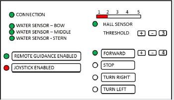
Each task requires the exchange of suitable data and this has been obtained by implementing a client-server architecture in which the Arduino UNO board that control the bouy, equipped with an additional Ethernet shield, hosts the server and the operator’s PC hosts the client. The Arduino server do not contain the webpage, but it simply contains a sketch (that is: a code that runs on the Arduino board) that periodically reads data from the sensor and, when it receives a request from the client, sends a response in accordance. This architecture represents a versatile solution that reduces the computational load on Arduino. Versatility is assured by the fact that the sketch is loosely coupled with the GUI webpage and communication is made using HTTP requests. So, every application that is capable to send HTTP requests can exploit the sketch, provided it knows the request name and the response format. In the future, instead of using a webpage, this architecture can be implemented on a desktop Android or iOS application, without the necessity to modify the Arduino sketch. The computational load is reduced since Arduino is not required to manage the webpage and, therefore, all its resources can be used for operating and governing the sensors and the actuators of the bouy. The above architecture has been enlarged by installing an additional Node.js server on the PC that communicates with the client. The Node.js is a JavaScript runtime (built on the Chrome’s V8 JavaScript engine) that uses an event-driven, non-blocking I/O model to read the data generated by a joystick. Through this node, the joystick is interfaced with the GUI. The webpage of the GUI is organized as shown in Figure 4.
LED indicators signal, with a green light, the connection with the buoy control board and with each of the sensors. Light turns to red if the connection is lost or, for the water sensors, if infiltration is detected. The moving red bar on the right describes the intensity of the magnetic field detected by the Hall sensor. By clicking on the +/- button, the operator can modify the threshold that activates the buoy motors in the Automatic Guidance Mode (there are five predetermined values for the threshold). By clicking on the yellow buttons, the operator can switch between the Remote Guidance Mode and the Automatic Guidance Mode, enable or disable the joystick, move the buoy forward or cause it to turn if the remote guidance is enabled. The +/- buttons serve to increase/decrease the speed by modifying the power supplied to the motors (there are five predetermined values for the supplied power) and the STOP button serves to turn the motors off. LED indicators signal with a green light the activated button. In the situation depicted in Figure 4, connection is on, the Remote Guidance Mode is active, the current value of the Hall sensor is 2 and chosen threshold is 3, the bouy has been commanded to move forward and the chosen level of supplied power is 4. When the joystick is enabled, forward motion, speed, right/left turns and stop are commanded, in an obvious way, by means of it.
Experimental Test
Tests of the prototypal platform have been carried on at two different locations with the aim, on one side, of assessing operability of the platform in the Remote Guidance Mode and in the Automatic Guidance Mode and, on the other, of evaluating its performances in geolocalizing underwater targets by means of an underwater acoustic positioning system (USBL).
Operability tests
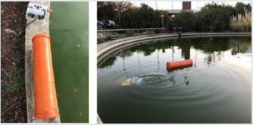
Functional tests of the prototypal platform have been carried on at the test pool of the Università Politecnica delle Marche, in Ancona, Italy. The circular pool has a diameter of 10m and a depth of 1.8m. Tests aimed at assessing operability of the platform in the Remote Guidance Mode and in the Automatic Guidance Mode from a control station located, in one case, at one edge of the pool and, in the other case, at 20m from it. In the first case, the PC has been equipped with a TP-LINKK tl-wn722n multidirectional antenna, with a gain of 4dBi and a data rate of 150 Mbps. In the second case, better performances have been obtained by employing a TP-LINKK tl-ant2414a unidirectional antenna with a gain of 14dBi. After testing internal components in laboratory, checking waterproof of the buoy’s hull and adjusting its buoyancy by regulating the ballast, the platform has been launched from the pool edge. The tow cable length, due to the limited dimensions of the pool, was chosen to be about 2m. The buoy has shown to be capable to tow the micro- ROV in the Remote Guidance Mode and to track it autonomously in the Automatic Guidance Mode, aligning and moving in response to the traction of the tow cable. The Wi-Fi connection was stable with a measured latency of about 0.2s. This delay did not affect, from a qualitative point of view, the experience of the operator in guiding the micro-ROV through the Wi-Fi/RJ- 45/Ethernet link. Using the unidirectional antenna and pointing it towards the buoy it was possible to get a stronger signal than that obtained by using the multidirectional antenna. By acting on the threshold, it was possible to tune the reaction of the automatic guidance system of the buoy to the traction force in such a way that manoeuvrability of the micro-ROV is qualitatively not affected by the presence of the tow cable. The typical tasks of a survey mission were performed. These include towing the micro-ROV with the buoy in Remotely Guidance Mode and guiding the micro-ROV over a submerged area and around a submerged structure to collect video data with the bouy in Automatic Guidance Mode. A single PC was used to host both GUI’s, switching from one to the other during the different phases of the mission. Figure 5 shows the micro-ROV and the buoy at the pool edge before launching and the platform in water. The micro-ROV’s light are on to make it easily visible in the picture.
Geolocalization of underwater targets
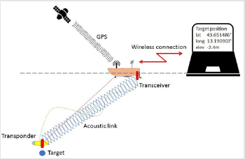
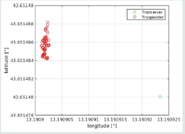
A specific task in which the platform can be employed is that of geolocalizing underwater targets. To this aim, the platform has to be equipped with a GPS, to locate its position in terrestrial coordinates, and with an underwater positioning system, to locate the position of the underwater target with respect to the platform [16]. A scheme of the resulting glocalization system is shown in Figure 6. The underwater positioning system used in the tests is an Ultra-Short Baseline positioning system that consists of an acoustic transceiver, that is attached to the buoy as an external appendix, and a transponder that is carried by the micro-ROV. The transceiver emits a series of acoustic pings which are reflected by the transponder and re-acquired by the transceiver. By measuring the time of flight and detecting the direction of arrival of the reflected signal, the system is able to evaluate the position of the transponder in a 3D coordinate system where the transceiver is located at the origin. This information is merged with GPS data, considering the displacement between the GPS receiving antenna and the transceiver position, to locate the transponder in terrestrial coordinates. One of the limits of USBL systems is that precision decreases linearly with the increase of the slant range between transceiver and transponder. The measurement error in evaluating the position of the transponder is about 3% of the slant range. In mapping large areas, it is therefore useful to keep the slant range small by installing the transceiver on a buoy that can follow at short distance the transponder carried by the micro-ROV, instead of operating from a vessel moored at the centre of the area. After validating the buoy as a communication bridge between the micro- ROV and a remote station in the operability tests described above, the transceiver of the USBL positioning system Evo Logics S2CR 18/34 has been installed as an external payload on the buoy, while a transponder has been installed on the micro-ROV. In addition, the buoy has been equipped with a GPS. Preliminary tests to assess feasibility of the positioning procedure have been performed in a 6mx10m pool, whose depth is 2.5m in a central 3mx5m zone and 1.2m along the perimeter. Acoustic emission of the USBL has been set to minimum power to reduce echoes. USBL data and GPS data were transmitted to the control consolle via Wi-Fi and processed to evaluate the positions of both the bouy and the micro-ROV. In a first series of tests in static conditions, the bouy and the micro-ROV kept stationary positions at a distance of about 1.9m. Measures acquired for 112s give an average value of the slant range of 1.8775m with a standard deviation of 0.0576m. By combining USB measurements with GPS data, the positions of the transceiver and of the transponder in WGS84 coordinates were evaluated. Figure 7 shows the position of the buoy that is obtained by averaging the GPS measurements and the positions of the targets obtained by each acoustic measurement. In this way it is easy to evaluate qualitatively the degree of accuracy of the geolocalization procedure. It has to be noted that the standard deviation of GPS position data, which is 0.006m, increases the positioning error, although the overall performances remain satisfactory: the average slant range is 1.91m with a standard deviation of 0.09m and the position of the target is determined with less than 6x10⁻⁶ degrees of uncertainty in latitude and less than 5x10⁻⁶ degrees of uncertainty in longitude (less than 1m in all directions).
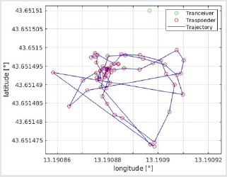
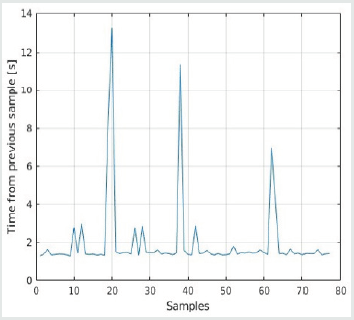
In a second series of tests, the micro-ROV moved the transponder inside the deepest area of the pool. Figure 8 shows the trajectory reconstructed from measurements and the position of the bouy (obtained by averaging the GPS measurements) in WGS coordinates over a time period of 157s. By setting a measurement rate of 5/7Hz, i.e. one measurement each 1.4s, for the USB positioning system, it has to be noted that some measurements are lost along the Wi-Fi channel the connect the buoy with the control consolle, as shown by Figure 9. These occurrences correspond to longer tracts in the reconstructed trajectory, but it possible to see from Figure 8 that the uncertainty they induce is limited to very short paths.
Conclusion
A simple prototype has been constructed to experiment usability and performances of a small, low cost, easy to manage robotic platform for underwater survey and exploration in shallow water. The next step of the work consists in equipping the platform with a radio link that allows remote guidance over longer distances (1Km-3Km) and a GPS system that facilitates it. As already mentioned, the buoy GUI will be modified in such a way to let the operator locate in real-time the bouy on a Google map by means of GPS data. Possibly, remotely operated small winches can be added to facilitate the management of the umbilical and of the tow cable by modifying their length. Further tests on the field will then be conducted. The envisaged final result is a novel robotic tool that will facilitate environmental protection, management of underwater installation and exploitation of marine resources in shallow water and littoral areas.
Acknowledgement
The authors acknowledge the work done by a team of gradute students and technician (V. Bartolucci, A. Mazza, M. Micello, A. Minischetti, G. Romani, M. Yakoubi and A. Pinelli) in assembling the platform.
References
- Scaradozzi D, Conte G, Sorbi L (2012) Assisting Micro-ROV Operators During Surveys in Fragile Envi- ronments. Sea Technology 53 (4).
- Conte G, Scaradozzi D, Mannocchi D, Raspa P, Panebianco L, et al. (2016) Development and Experi- mental Tests of a ROS Multi-agent Structure for Autonomous Surface Vehicles. Journal of Intelligent and Robotic Systems 92(3): 705-718.
- Pascoal A, Oliveira P, Silvestre C, Sebastiao L, Rufino M, et al. (2000) Robotic ocean vehicles for marine science applications: the European ASIMOV project. In Proceedings OCEANS 2000 MTS/IEEE Conference and 36 Exhibition 1: 409-415.
- Healey AJ, Pascoal A, Santos R (2002) Shallow water hydrothermal vent survey in Azores by cooperating ASV and AUV. Naval Postgraduate School Report MPS-39 Monterey.
- Ferreira H, Martin A, Dias A, Almeida C, Almeida J, et al. (2006) ROAZ autonomoussurface vehicle design and implementation. Robotica 41.
- Djapic V, Nad D (2010) Using collaborative Autonomous Vehicles in Mine 42 Countermeasures. In Proceedings OCEANS 2010 MTS/IEEE Conference p. 24-27.
- Conte G, DeCapua P, Scaradozzi D (2016) Designing the NGC system of a small ASV for tracking underwater targets. Robotics and Autonomous Systems 76: 46-57.
- Conte G, Scaradozzi D, Mannocchi D, Raspa P, Panebianco L, et al. (2016) Experimental testing of a cooperative ASV-ROV multi-agent system. IFAC-Papers OnLine 49(23): 347-354.
- Gray A, Schwartz E (2016) Anglerfish: An ASV Controlled ROV. In The 29th Florida Conference on Recent Advances in Robotics.
- Sarda E, Dhanak M (2017) A USV-Based Automated Launch and Recovery System for AUVs. In IEEE Journal of Oceanic Engineering 42: 37-55.
- Jung DW, Hong SM, Lee JH, Cho HJ, Choi HS, et al. (2018) A Study on Unmanned Surface Vehicle Combined with Remotely Operated Vehicle System. Proceedings of Engineering and Technology Innovation 9: 17-24.
- https://www.asvglobal.com/tag/c-worker-7/.
- Conte G, Scaradozzi D, Animobono D (2020) A 4G robotic platform for shallow water operations. In Pro- ceding ISOPE 2020.
- Scaradozzi D, Sorbi L, Zoppini F (2014) 3D video streaming from a remotely operated vehicle. Proceedings of the 6th European Embedded Design in Education and Research Conference (EDERC) p. 50-54.
- https://www.openrov.com/products/openrov28/.
- Scaradozzi D, Panebianco L, Ciuccoli N, Zingaretti S, Egi SM, et al. (2017) Underwater position estimation for an underwater vehicle using unscented Kalman filter. Proceedings 25th Signal Processing and Communications Applications Conference (SIU) p. 1-4.

Top Editors
-

Mark E Smith
Bio chemistry
University of Texas Medical Branch, USA -

Lawrence A Presley
Department of Criminal Justice
Liberty University, USA -

Thomas W Miller
Department of Psychiatry
University of Kentucky, USA -

Gjumrakch Aliev
Department of Medicine
Gally International Biomedical Research & Consulting LLC, USA -

Christopher Bryant
Department of Urbanisation and Agricultural
Montreal university, USA -

Robert William Frare
Oral & Maxillofacial Pathology
New York University, USA -

Rudolph Modesto Navari
Gastroenterology and Hepatology
University of Alabama, UK -

Andrew Hague
Department of Medicine
Universities of Bradford, UK -

George Gregory Buttigieg
Maltese College of Obstetrics and Gynaecology, Europe -

Chen-Hsiung Yeh
Oncology
Circulogene Theranostics, England -
.png)
Emilio Bucio-Carrillo
Radiation Chemistry
National University of Mexico, USA -
.jpg)
Casey J Grenier
Analytical Chemistry
Wentworth Institute of Technology, USA -
Hany Atalah
Minimally Invasive Surgery
Mercer University school of Medicine, USA -

Abu-Hussein Muhamad
Pediatric Dentistry
University of Athens , Greece

The annual scholar awards from Lupine Publishers honor a selected number Read More...


