Lupine Publishers Group
Lupine Publishers
Menu
ISSN: 2690-5779
Research ArticleOpen Access 
Investigation Axial Global Directional in ANSYS Software of Concrete Mixed Beam Structures Volume 1 - Issue 1
Semih Taskaya1* and Selim Taskaya2
- 1Department of Engineering Metallurgy and Materials, Faculty of Technology, University of Firat, Turkey
- 2Department of Architecture and Urban Planning, School of Vocational, University of Coruh Artvin, Turkey
Received: September 24, 2019 Published: October 10, 2019
Corresponding author: Department of Architecture and Urban Planning, School of Vocational, University of Coruh Artvin, Turkey
Abstract
The model structure of the coordinated systems under the name of concrete-mixed beam structures using ANSYS 12.0 software was designed in 3D. Concrete mixture was selected as the element type of the model structure. Model prototype was created by measuring distance dependent with 16 coordinate points. Mesh segmentation was applied to the 3D concrete mixed beam model and 75 N/mm2 load and 32.174ft / sec2 acceleration motion were applied to the carrier systems. In the results of the application, global directional changes between the model groups were examined. As a result of the global investigations, ANSYS software has determined that the mechanical improvements should be at the joints where the beams connected to the axes and the concrete bases meet.
Keywords: Concrete mixtures; Beams; ANSYS; Global; Axial
Introduction
With the Workbench platform offered by ANSYS, many engineering works can be accessed on one screen. ANSYS Workbench is a very effective program for simulation dependent product development with advanced parameter management. With ANSYS Workbench, analytics from different engineering disciplines can be managed from a single center [1]. The elements of a reinforced concrete building can be divided into undefined boundaries, with or without support. For example, partition walls, floor coverings are non-bearing elements. In contrast, floor slabs, beams, columns and foundations are examples of elements of the carrier. The slabs are two-dimensional and generally bearing elements which are directly affected by vertical loads. They may appear to have been obtained simply by joining the beams in two directions. They transmit the loads to the beams that support them at their sides and they are concrete together. The beams form a support for the slabs and are one-dimensional support elements. Generally, positive bending moment and negative bending moment occur in their support. Consequently, the main accessories to receive the tensile stresses in the sections are located at the bottom in the opening and at the top in the support. When the beams transmit their loads to the columns they are supported, they form a three-dimensional frame that allows the carrier system to place horizontal loads. Columns collect vertical loads from each floor and transmit them to the foundation and therefore they are the main bearing element of the structure. Any damage to these elements often affects the entire structure. Columns transmit their loads to the ground through foundations. Since the bearing capacity of the ground is smaller than the concrete, the foundation is formed by expanding the column section. The foundations, which are generally rectangular in shape and are separated in the plan, are connected to each other by bond beams in two directions [2]. Cui et al. [3], a new hybrid modeling approach was proposed in this study to estimate the mean indoor air temperatures of both the upper floor and the lower floor.
This ”hybrid” solution combines both the gray box, the RC model and the black box. An advanced RC model is used to estimate the building average temperature and the black box model, which utilizes supervised machine learning algorithms, is used to estimate the temperature difference between the lower floor and the upper floor [3]. Bedeir et al. [4] made a numerical model of a two-storey, third scale reinforced concrete masonry building that was subjected to semi-static cyclic lateral loading consisting of walls in orthogonal directions. The results of ten experimentally tested walls were used to validate the modeling approach used to construct the building model. The models were able to accurately capture the response of individual walls and the building under test. Numerical results have shown that the overall ductility of the building is higher than the constituent walls under eccentric load, which is consistent with experimental results [4]. Taskaya et al. [5] in their study, Ramor 500 steel with different parameters by submerged arc welding method to make the process, ANSYS package software modeling and thermal analysis were made. As a result of the study, as the welding voltage increases, the simulatic changes of the temperature in the distance-time curves have been investigated [5]. Taşkaya & Taşkaya [6] investigated the temperature, pressure, velocity and mass flow behavior of hot and cold-water fluid mixture passing through a faucet volume designed in three dimensions. The parameters obtained from the simulation analysis data results indicate that the fluid of the global axes in the model volume according to the fluid in the pressure output mixture; it has been investigated that the change in mass and knot flow velocity is constant and temperature and pressure increase [6]. In Taşkaya & Taşkaya [7] studies, AISI 310 stainless steel cylinder with 40 mm outer diameter was designed in ANSYS Workbench 12.0 module.
The static structural analysis of the steel was analyzed by applying a force of 1000 N in the -y axis direction from the steel top plate region. As a result of the analyzes, it was observed that the load distributions affected by the static structure of the cylindrical steel are concentrated in the upper and lower regions [7]. Taşkaya [8] investigated deformation, mechanical and elastic stress analyzes on beam axes by applying different load and constant pressure to 3D lattice roof model with an isotropic steel material in ANSYS package program [8]. In the Taşkaya & Taşkaya [9] studies, the hangar roof model of the formed hanging roof model, which has a 46x50mm base supporting cylinder pipe diameter with 54 dimensional and 34 corner coordinate points, applied 200 Newton force to 5 support beam points. With the applied force effect, they mapped the deformation and stress distributions of the roof top beam and supporting nodes. As a result of the analysis, they observed that the deformation and stresses in the load bearing upper beam and base coordinate points increased and decreased in the front supporting beam points [9]. Gür et al. [10] ANSYS software in different temperature and tensile parameters Al material and SIC metal matrix composite creep elongation movement and investigated the relationship between elastic stresses [10].
The aim of this study; With the creation of measuring points from the Workbench module of ANSYS software, 3D concrete-mixed beam structures are tested according to load and acceleration. With the results of this simulation test analysis, structural errors and deformations related to axes were determined and mechanical improvements in the structures were determined. The best results are obtained with the ANSYS package software used under the name of finite elements by determining the appropriate parameter without passing the application industry.
Experimental
ANSYS Model Design
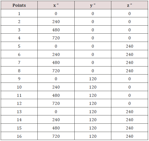
In this study, concrete beam model was created with the coordinate points given in Table 1 in the static structure section of Workbench module in ANSYS 12.0 software. The structural application element type of this design was selected as “concrete” mixture from ANSYS engineering data library. The 16 coordinate points given in Table 1 are the structural system points created by measuring the beams. In the model design of the coordinate points given in Table 1, all individual data are defined at 16 different points. The ‘inch (“) ‘length unit is used to calculate the coordinate points. This is due to the fact that coordinate systems do not generate fractional numbers.
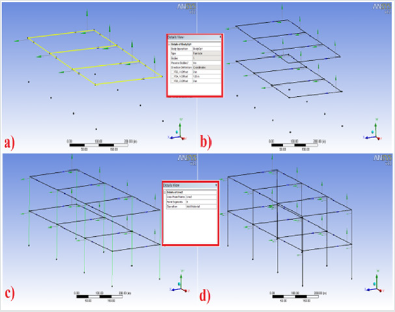
In the model design shown in Figure 1, the measuring points according to 16 separate axes are defined in a separate ANSYS Workbench module. After the measurement coordinate points have been defined, the 1st floor beam lines of the prototype are combined. The rear beam coordinate points of the 1st floor shown in Figure 1a are combined. In the same way, the front beam points of Figure 1b of the 1st floor is joined. Then, in Figure 1c, the process of joining all axes with 6 bases is formed. In Figure 1d, axis definitions are made for these completed beam points. Figure 2 shows the second-floor formation points of the building model. Here, the measurement coordinates created on the first floor are used and the “operation” section from ANSYS Workbench module is used in the design of the second floor. The first-floor module axes are cloned to the second floor so that the same coordinate points are defined and not reconstructed repeatedly. In Figure 2a, all the 1st floor axes are selected. In Figure 2b, the second-floor model is created on these axes with a height of 120 inches in the y-axis and a ceiling height of about 305cm. In Figure 2c, this structure prototype, which is designed as 2nd floor design, is defined as 8 supporting leg beams towards the base. After this stage, as shown in Figure 2d, the 8-foot carrier beams of the prototype model are completed. An I profile is defined to the concrete beam model beam points. A thickness value is assigned to these I profiles. The cross-section modules w1, w2, w3 of the carrier profiles are 7, 7, 16 inches respectively; The thickness values of t1, t2, t3 are 0.63 inches respectively. After these values are applied to the model, the sections are aligned in the module.
Figure 1: Concrete mixed beam structures a) Forming the first beam rear beam b) Forming the first beam front layer c) Joining all the beam layers of the first-floor d) Determining and showing the beam layers in 6 axes.
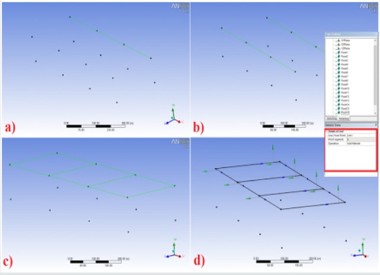
Figure 2: Concrete mixed beam structures a) Selecting all the 1st floor axes b) Creating the 2nd floor design c) Forming the carrier beam points d) Finished beams.
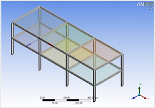
In Figure 3, the structure beams are defined with the concrete slab material and the slab formwork. 6 concrete floor slabs are individually modeled at a thickness of about 5 inches and about 13 cm. Starting from the 2nd floor, 3 separate concrete slabs of the 2nd floor are made. Then the concrete floor slabs of the 1st floor are applied and the concrete floor slabs applied to the beams of the building model are applied. In order to avoid deviations from these angles in any angle, all beam sections are defined at the z-axis 90 o. All material beam groups of the building model are completed and a partitioning is applied to the model for mesh definition.
Mesh of Model Structure and Load Definition
Figure 5: Concrete mixed beam structures a) fixation of the supporting legs b) pressure identification c) standard center of gravity d) acceleration identification.
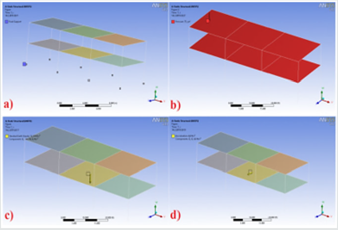
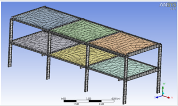
After the structure model design stage is provided, a mesh segmentation is defined for the model as shown in Figure 4. This definition ensures that the mesh spacings shall be shallow and the concrete spacings shall be wide in suitable mesh spacings. The fixing of the concrete mixed structures shown in Figure 5a to the support leg points is performed. This ensures that the support beam points do not move during load application. Figure 5b describes the application of a pressure of 75 N/mm2 to the concrete mixing zones. In Figure 5c, the standard center of gravity of the model is determined and a value of 32.174ft / sec2 is defined in the global coordinate system as an inch length unit towards the –y axis. This means that the building model has gravity to the center. As a final step, in Figure 5d, the structural model is given an acceleration of 6.4ft / sec2 in inches. Here, the mechanical results that occur by giving a vibration motion to the model under the effect of pressure are examined.
Results and Discussion
Figure 6: Concrete mixed beam structures a) x-axis global directional changes b) y-axis global directional changes c) z-axis global directional changes d) structural errors.
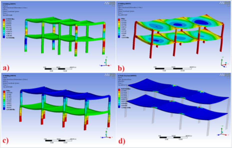
As a result of the analysis made against pressure and acceleration in the workbench module of ANSYS software of concrete mixture beam structures, global directional changes and structural errors between axes were examined. In Figure 6a, b & c, the effects of directional shape changes according to global coordinates of the model structure are examined. These effects increased in Figure 6a in the x-global coordinate of the upper knot regions of the beams and in the main contact regions where the 1st and 2nd layers meet. In Figure 6b, it increased the stress intensities in the load bearing foot systems in the stable equilibrium position with the pressure it exerted on the y axis in the y global coordinate. In Figure 6c, it is observed that shape change effects in z axis global coordinate regions are mostly in the end base region of the carrier leg systems. In the analysis shown in Figure 6d, this prototype shows the construction errors shown in the model analysis. In systemic structure analysis, the system warns that the mechanical improvements should be at the joints where the beams connected to the axes and the concrete bases meet. Here, especially in ANSYS package software, Workbench module wants to support and strengthen these points in terms of strength.
Conclusion
The results determined in the Workbench module of ANSYS 12.0 software of the concrete mixed beam structures are given below. Total deformation of the second floor by creating a sedimentation effect in the middle of the concrete base mold max. effect was examined. The concrete forms of the 1st floor showed less deformation than the 2nd floor. Min. Carrier foot systems have taken their values. Stress ratio increased as load and acceleration increased. The regions where the shape change rates are most influenced starting from the 2nd floor are observed to be high in the collapse regions caused by gravity at the central point of the concrete mixtures. The contact areas in the upper regions have increased towards the tensile and lower pulley regions compressive strength. In the x axial spherical analysis, the upper knot regions of the beams and the main contact regions where the 1st and 2nd layers meet are increased. In the axial global directional analysis, the stress intensities were increased in load-bearing leg systems at a stable equilibrium with pressure. In the z axial global direction analysis, it is observed that the shape change effects in the regions are mostly in the end base region of the bearing leg systems. ANSYS software system warned that mechanical improvements should be at the joint points of the beams connected to the axes and the concrete bases in the systemic structure analysis.
References
- (2019) CadSay.
- (2019) İ
- Cui B, Fan C, Munk J, Mao N, Xiao F, et al. (2019) A hybrid building thermal modeling approach for predicting temperatures in typical, detached, two-story houses. Applied energy 236: 101-116.
- Bedeir H, Shedid M, Okail H, Hamdy O (2019) Numerical modeling of a two story third-scale reinforced masonry shear wall building subjected to quasi-static lateral loading. Engineering Structures. 181: 310-323.
- Taskaya S, Gur AK, Orhan A (2019) Joining of Ramor 500 Steel by Submerged Welding and its Examination of Thermal Analysis in Ansys Package Program. Thermal Science and Engineering Progres 11: 84-110.
- Taşkaya S, Taşkaya S (2018) Simulation of the Distribution of Fluid Passing the Faucet Model Volume According to Global Coordinates in Ansys Software. First International Multidisciplinary Studies Battalgazi Congress Turkey 2: 114-125.
- Taskaya S, Taskaya S (2018) Investigation of Static Structure Effect According to Axial Coordinates by Using Finite Element Method in Ansys Workbench Software of AISI 310 Austenitic Stainless Cylindrical Model Steel. International Journal of Scientific Engineering and Science 2(11): 65-70.
- Taşkaya S (2018) Investigation of Mechanical and Elastic Stresses In Ansys Program By Finite Elements Method of 3D Lattice Roof Model. Mugla Journal of Science and Technology 4(1): 27-36.
- Taskaya S, Taskaya S (2019) Mapping of Stress Distributions of Hangar Roof Systems in Ansys Software. International Journal of Advance Engineering and Research Development 6(2): 82-89.
- Gur AK, Taskaya S, Star T, Solid N (2017) Investigation of Creep and Elastic Properties of Metal Matrix Composite Materials by the Effect of Temperature by Ansys Method. 2nd International Conference on Material Science and Technology in Cappadocia, 171-177.

Top Editors
-

Mark E Smith
Bio chemistry
University of Texas Medical Branch, USA -

Lawrence A Presley
Department of Criminal Justice
Liberty University, USA -

Thomas W Miller
Department of Psychiatry
University of Kentucky, USA -

Gjumrakch Aliev
Department of Medicine
Gally International Biomedical Research & Consulting LLC, USA -

Christopher Bryant
Department of Urbanisation and Agricultural
Montreal university, USA -

Robert William Frare
Oral & Maxillofacial Pathology
New York University, USA -

Rudolph Modesto Navari
Gastroenterology and Hepatology
University of Alabama, UK -

Andrew Hague
Department of Medicine
Universities of Bradford, UK -

George Gregory Buttigieg
Maltese College of Obstetrics and Gynaecology, Europe -

Chen-Hsiung Yeh
Oncology
Circulogene Theranostics, England -
.png)
Emilio Bucio-Carrillo
Radiation Chemistry
National University of Mexico, USA -
.jpg)
Casey J Grenier
Analytical Chemistry
Wentworth Institute of Technology, USA -
Hany Atalah
Minimally Invasive Surgery
Mercer University school of Medicine, USA -

Abu-Hussein Muhamad
Pediatric Dentistry
University of Athens , Greece

The annual scholar awards from Lupine Publishers honor a selected number Read More...


