Lupine Publishers Group
Lupine Publishers
Menu
ISSN: 2690-5779
Review Article(ISSN: 2690-5779) 
Computational modelling of plate-fin and tube heat exchanger for heat transfer and pressure drop analysis Volume 1 - Issue 3
Solomon Mesfin12, L Syam Sundar2* and Antonio CM Sousa2
- 1Department of Mechanical Engineering, University of Gondar, Gondar, Ethiopia
- 2Centre for Mechanical Technology and Automation (TEMA–UA), Department of Mechanical Engineering, University of Aveiro, Portugal
Received: October 02, 2020 Published: October 19, 2020
Corresponding author: L Syam Sundar, Centre for Mechanical Technology and Automation (TEMA–UA), Department of Mechanical Engineering, University of Aveiro, Portugal
DOI: 10.32474/JOMME.2020.01.000113
Abstract
The heat transfer and pressure drop characteristics of plate-fin and tube heat exchanger is analyzed by using computational modeling. The parameters which are considered in this analysis are space between the two fins, length of the fin and tube ellipticity. The governing equations of continuity, momentum and energy are solved using the commercially available FLUENT software. Seven different cases are considered for heat transfer and pressure drop analysis. The main findings are related to the spacing between the fins, which is critical in terms of pressure drop. The tube ellipticity provides an increase in heat transfer coefficient and reduces in pressure drop.
Keywords: plate-fin and tube exchanger; numerical analysis; tube ellipticity; pressure drop.
Introduction
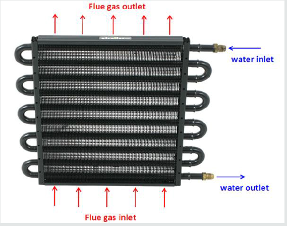
The plate-fin and tube heat exchanger are a cross-flow type
heat exchanger, which uses plates as fins as indicated in (Figure
1); therefore, the flow external to the tubes is unmixed. Often, it is
categorized as a compact heat exchanger to emphasize its relatively
high heat transfer surface area to volume ratio. The plate fin and
tube heat exchanger is widely used in many industries, including
the aerospace industry, for its compactness and low weight.
Different types of fin patterns, in addition to the plate, exist, such as
louver, convex-louver, and wavy; however, in general, the plate fin
tends to be the best in terms of performance and of constructional
effectiveness. The tube geometry used in plate fin and tube heat
exchangers is either circular or elliptical. The majority of the
studies dealing with plate fin and tube heat exchangers have been
conducted resorting to experiments.
Shepherd [1] analyzed early experimental data for heat
transfer of plate fin and circular tube heat exchanger. Later on,
Schulemberg [2] extended the analysis to plate fin and elliptical
tubes. Kayansayan [3] investigated experimentally the effects of
the outer surface geometry on the performance of flat plain fin
and circular tube heat exchangers with four-row coils. Jang et
al. [4] studied fluid flow and heat transfer over a multi row (1–6
rows) plate-fin and tube heat exchanger both numerically and
experimentally. They considered effects of different geometrical
parameters such as tube arrangement, tube row numbers and
fin pitch (8–12 fins per inch) for the Reynolds number (based
on the fin spacing and the frontal velocity) ranging from 60
to 900 and observed an average heat transfer coefficient of
staggered arrangement is 15%–27% higher than that of in-lined
arrangement, while the pressure drop of staggered configuration
is 20%–25% higher than that of in-lined configuration. Wang et al.
[5] investigated experimentally heat transfer and pressure drop
for plate fin and tube heat exchanger. Beecher et al. [6] reported
heat transfer data for twenty wavy geometries. Kays et al. [7]
analyzed heat transfer and pressure drop of heat exchanger with
louvered fins. Achaichia et al. [8] experimentally studied the heat
transfer and pressure drop of tube and louvered fin surfaces; later
on the same authors [9] conducted a numerical study for flow in
the laminar regime. Webb et al. [10] performed a flow visualization
study of the louvered fin geometry with a flat tube. Sahnoun et al. [11] developed an analytical model for predicting air-side heat
exchanger performance of louvered fin geometry. Rocha et al. [12]
experimentally estimated the overall heat transfer coefficient of
plate fin heat exchangers by considering circular and elliptical
tubes. Kundu et al. [13] conducted a dimensional optimization
for plate fin and tube heat exchangers with equilateral staggered
triangular and rectangular pitch. Romero-Mendez et al. [14] used
numerical techniques to estimate the effect of spacing between
fins on heat transfer and pressure drop for single row fin and tube
heat exchanger. Wang et al. [15] experimentally analyzed the effect
of tube rows, fin pitch, and tube diameter on heat transfer and
pressure drop for plate fin and tube heat exchanger. Wang et al.
[16] presented correlations of the Colburn and friction factors for
plate fin and tube heat exchangers. Saboya et al. [17] determined
the average heat transfer coefficient for plate fin and elliptic tube
heat exchangers using the naphthalene sublimation technique.
Torikoshi et al. [18] numerically investigated a plain fin and tube
heat exchanger. Erek et al. [19] numerically investigated the effect
of fin geometry on heat transfer and pressure drop for plate fin
and tube heat exchangers, but they used one particular mass flow
rate of the flue gas. Abu Madi et al. [20] determined the effect of
geometrical parameters of flat and corrugated fins and the results
are presented in terms of Colburn and friction factors.
The present work is focused on the numerical investigation
estimation of heat flow, pressure drop, and temperature and
velocity fields for the plate fin and tube heat exchanger with one
row tube configuration; the analysis will be focused on the effect of
fin spacing, ellipticity and fin height on the numerically predicted
parameters.
Computational modeling
Description of the problem
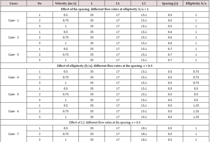
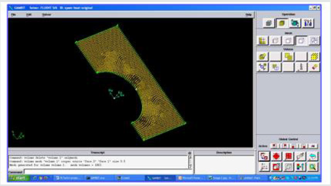
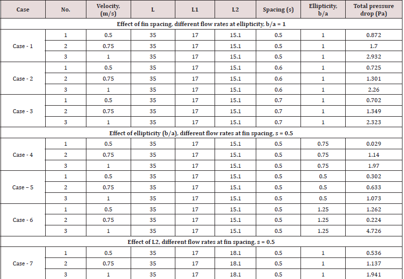
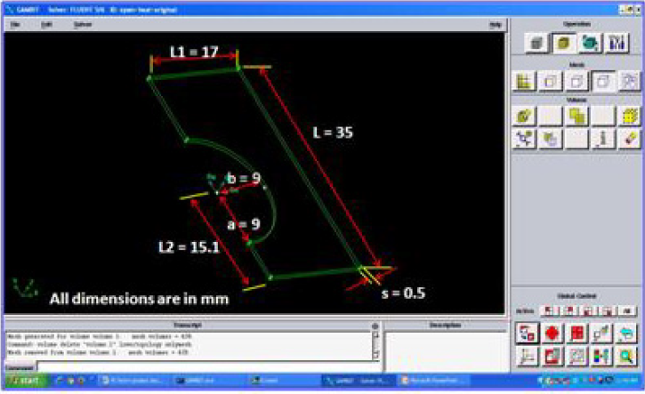
The plat fin and tube heat exchanger, which is the object of the present study, is schematically depicted in (Figure 2a). The various fin geometries and its dimensions used in this analysis are shown in (Table 1). The computational flue gas flow passage is determined by the spacing of the fins and the distance between the centers of the tube for each consecutive pass. The fins are equidistant and the flow area shown in (Figure 2b,2c) is assumed to be representative of the overall flow passage. The GAMBIT software is used to model the computational domain (Figure 3a), and its meshed view is shown in (Figure 3b). The inlet boundary condition for the flue gas is given by the velocity (0.5, 0.75 and 1.0 m/s) and temperature (1000 K), and the outlet boundary condition is the pressure and no variation of the temperature in the stream wise direction. The flue gas is assumed to have the properties of air. The cooling fluid circulating in the tube is water and it is considered to be fully developed turbulent flow. The convective heat transfer between the tube and fin is calculated using Gnielinski equation [21], which is given as:
Figure 2: Schematic representation of fin and tube heat exchanger (b) single fin with tubes arrangement (c) flow area between the fins.
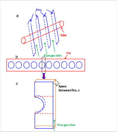
Figure 3(a): Prototype of flow passage between the fins and with dimensions developed in GAMBIT software.
The no-slip boundary condition is applied to the tube and the plate fins. The remaining computational boundaries take a symmetry condition. The material of the tube and plate fins is assumed to be copper.
Governing equations
The process is assumed to steady state and the governing
equations describing conservation of mass, momentum and energy
are expressed in vector form as follows [22]:
Where, σ_k and σ_ε are the turbulent Prandtl numbers for
the turbulent kinetic energy and its dissipation. Turbulent kinetic
energy (k) and its dissipation rate (ε) are coupled to the governing
equations via the turbulent viscosity relation (μ_t=ρC_μ k^2/ε). C_μ
is not a constant value as in the standard k–ε model. The empirical
constants, C_2, σ_k and σ_ε are equal to 1.9, 1.0 and 1.3, respectively
[24].
The transport equations i.e. Eq. (5) and Eq. (6), after their
discretization, are solved sequentially along with the discretized
conservation equations. The discretization of the transport
equations and conservation equations is conducted using the finite
volume method [23] along with a second-order upwind scheme. The
continuity equation and momentum equation are solved through
an iterative scheme by using the coupling between pressure and
velocity is employed through the Semi Implicit Method for Pressure
Linked Equations (SIMPLE) algorithm [25]. In this paper, a finite
volume based flow solver of computational fluid dynamics software
FLUENT 6.0 was employed for the simulation.
Results and discussion
Static temperature contours
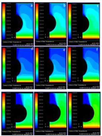
Figure 4: Static temperature contours when the tube ellipticity, a/b = 1 with effect of space between the fins (a) s = 0.5, v = 0.5 m/s (b) s = 0.5, v = 0.75 m/s (c) s = 0.5, v = 1.0 m/s (d) s = 0.6, v = 0.5 m/s (e) s = 0.6, v = 0.75 m/s (f) s = 0.6, v = 1.0 m/s (g) s = 0.7, v = 0.5 m/s (h) s = 0.7, v = 0.75 m/s (i) s = 0.7, v = 1.0 m/s.
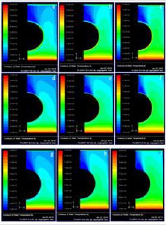
Simulations were conducted for different parameters to determine the static temperature and total pressure fields. Three different velocities of flue gas (0.5 m/s, 0.75 m/s and 1.0 m/s) for all cases studied. The static temperature field for the three velocities for fin spacing, s, equal to 0.5 mm and tube ellipticity, a/b, of 1 is reported in Figure 4 (a-c). As expected, when the velocity of flue gas increases, the outlet temperature of flue gas also increases; the outlet temperatures are 341 K, 362 K and 380 K for inlet velocities of 0.5 m/s, 0.75 m/s and 1.0 m/s, respectively. The effect of fin spacing is also analyzed and, to this purpose, three fin spacing are considered: the manufacturer’s standard fin spacing of 0.5 mm, 0.6 mm and 0.7 mm. The static temperature field for each of the three tested flue gas inlet velocities (0.5 m/s, 0.75 m/s and 1.0 m/s) is reported in (Figure 4) (d-f) for a fin spacing, s, 0.6 mm and tube ellipticity, a/b, equal to 1. The outlet temperatures are 343 K, 362 K and 381 K for the inlet velocities of 0.5 m/s, 0.75 m/s and 1.0 m/s, respectively; these results are equal or slightly higher than those for the fin spacing of 5 mm, a finding, which is physically consistent, considering the slight reduction in mixing and consequent reduction in turbulence. The static temperature field for the three inlet velocities with a fin spacing, s, of 0.7 mm and tube ellipticity, a/b, equal to 1, presents a similar trend, namely, 346 K, 367 K, and 386 K for the inlet velocities of 0.5 m/s, 0.75 m/s and 1.0 m/s, respectively; the results are presented in (Figure 4) (g-i). Therefore, it can be said that an increase in grid spacing will lead to a decrease of the difference between the inlet and outlet temperature.
Figure 5: Static temperature contours when the space between the fins s = 0.5 with effect of ellipicity (a) a/b = 0.75, v = 0.5 m/s (b) a/b = 0.75, v = 0.75 m/s (c) a/b = 0.75, v = 1.0 m/s (d) a/b = 0.5, v = 0.5 m/s (e) a/b = 0.5, v = 0.75 m/s (f) a/b = 0.5, v = 1.0 m/s (g) a/b = 1.25, v = 0.5 m/s (h) a/b = 1.25, v = 0.75 m/s (i) a/b = 1.25, v = 1.0 m/s
The effect of ellipticity on the temperature field is analyzed for
the 0.5 mm fin spacing (s) in what follows. The results reported in
Fig. 4 are for the circular tube, which has an ellipticity (a/b) of 1;
the other values of tube ellipticity that are considered in this study
are 0.75, 0.5 and 1.25, respectively. The static temperature field
for the tested inlet velocities (0.5 m/s, 0.75 m/s and 1.0 m/s) with
tube ellipticity, a/b, of 0.75 is shown in (Figure 5) (d-f); the flue gas
outlet temperatures are 345 K, 365 K and 384 K for the flue gas
inlet velocities of 0.5 m/s, 0.75 m/s and 1.0 m/s, respectively. For
the ellipticity, a/b, of 0.5, the outlet temperatures are 391 K, 425 K
and 455 K with the flue gas inlet velocities of 0.5 m/s, 0.75 m/s and 1.0 m/s, respectively; while for the ellipticity, a/b, of 1.25, the outlet
temperatures are 362 K, 363 K and 363 K with the flue gas inlet
velocities of 0.5 m/s, 0.75 m/s and 1.0 m/s, respectively. For the 5
mm fin spacing, the tube ellipticity, a/b, of 1.25 yields the lowest
outlet temperature (363 K) for the inlet velocity of 1 m/s, in fact,
for this ellipticity, the outlet temperature is practically independent
of the inlet velocity in the tested range. The tube ellipticity of 0.5 is
the one that leads to the highest outlet temperatures indicating the
lowest thermal performance for the heat exchanger.
The influence of the length L2 (Figure 3a) on the temperature
field is also analyzed. The change in L2 is equivalent to alter the
distance between tube passes. The temperature field for the length
L2 equal to 15.1 mm and fin spacing of 0.5 mm is shown in Figure
4 (a-c). The temperature field for the length L2 equal to 18.1 is
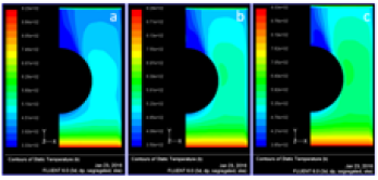
reported in Figure 6 (a-c). The outlet temperatures are 333 K, 350
K and 365 K for the inlet velocities of 0.5 m/s, 0.75 m/s and 1.0 m/s.
The increased length L2 is not that much suggestible, because the
outlet flue gas temperature is reducing for all the velocities.
Figure 6:Static temperature contours when the space between the fins s = 0.5 with effect of L2 (a) v = 0.5 m/s (b) v = 0.75 m/s (c) v = 1.0 m/s
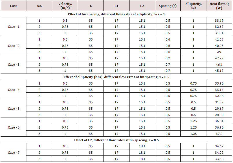
Based on the temperature profiles, the amount of heat flow
through the fin is calculated from the below equation and the values
are presented in (Table 2).
Q=kA(ΔT)/L (7)
From the (Table 2), the ellipticity of the tube b/a = 1 and at flow rate of 0.5 m/s, the highest heat flow through fin is achieved. Whereas the ellipticity of the tube b/a = 0.5 and at flow rate of 1.0 m/s, the lowest heat flow through fin is achieved.
Figure 7: Total pressure contours when the tube ellipicity, a/b = 1 with effect of space between the fins (a) s = 0.5, v = 0.5 m/s (b) s = 0.5, v = 0.75 m/s (c) s = 0.5, v = 1.0 m/s (d) s = 0.6, v = 0.5 m/s (e) s = 0.6, v = 0.75 m/s (f) s = 0.6, v = 1.0 m/s (g) s = 0.7, v = 0.5 m/s (h) s = 0.7, v = 0.75 m/s (i) s = 0.7, v = 1.0 m/s
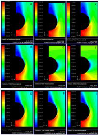
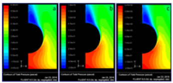
The total pressure is the pressure measured by bringing the flow to rest isentropically (without loss). The total pressure contours (Pa) at velocity of flue gases 0.5 m/s, 0.75 m/s and 1.0 m/s at fin spacing, s = 0.5 mm and at tube ellipticity, a/b = 1 were shown in (Figure 7) (a-c). It is observed from the figure, with the increase of velocity of flue gases increases, the total is decreasing. Similarly, the total pressure contours (Pa) at velocity of flue gases 0.5 m/s, 0.75 m/s and 1.0 m/s at tube ellipticity, a/b = 1 and at fin spacing, s = 0.6 mm and s = 0.7 mm were shown in Figure 7 (d-f), Figure 7 (g-i) respectively. The effect of total pressure on ellipticity is also studied. (Figure 8) (a-i) represents the total pressure contours at fin spacing s = 0.5 mm with effect of ellipticity at various velocities. (Figure 9) (a-c) represents the total pressure contours when the space between the fins s = 0.5 with effect of L2. The total pressure drop across the flow area for all the cases are summarized in (Table 3).
Figure 8: Total pressure contours when the space between the fins s = 0.5 with effect of ellipicity (a) a/b = 0.75, v = 0.5 m/s (b) a/b = 0.75, v = 0.75 m/s (c) a/b = 0.75, v = 1.0 m/s (d) a/b = 0.5, v = 0.5 m/s (e) a/b = 0.5, v = 0.75 m/s (f) a/b = 0.5, v = 1.0 m/s (g) a/b = 1.25, v = 0.5 m/s (h) a/b = 1.25, v = 0.75 m/s (i) a/b = 1.25, v = 1.0 m/s
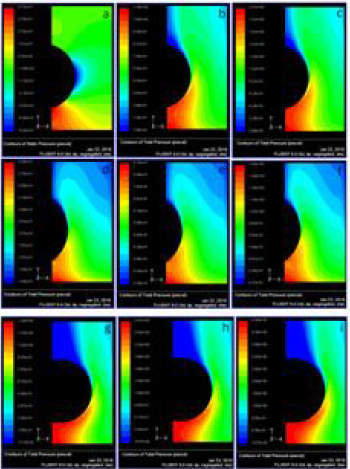
Figure 9: Total pressure contours when the space between the fins s = 0.5 with effect of L2 (a) v = 0.5 m/s (b) v = 0.75 m/s (c) v = 1.0 m/s
Conclusion
The present work focus on the heat flow and total pressure distribution across the plate fin and tube heat exchanger has been analyzed by using FLUENT software. The prototype of the plate fin and tube heat exchanger is designed in GAMBIT software and exported to FLUENT software for solving purpose. The study consists of several cases of fin geometry such as fin tube center, fin height; fin spacing and tube ellipticity are investigated, numerically. The following conclusions are drawn from the analysis. The distance between fins has an important effect on pressure drop. For the fin geometry with ellipticity value of 0.75 has the smallest static and total pressure drops. Since flue gas velocity is decreased, the lower pressure drop value is obtained. The ellipticity of the tube b/a = 1.25 and at flow rate of 1.0 m/s, the highest pressure drop across the fin is achieved. The ellipticity of the tube b/a = 1 and at flow rate of 0.5 m/s, the highest heat flow through fin is achieved. Whereas the ellipticity of the tube b/a = 0.5 and at flow rate of 1.0 m/s, the lowest heat flow through fin is achieved. Greater heat transfer and pressure drop values are obtained as the fin height is increased, due to the increased heat transfer surface area. The decrease in tube spacing causes the increase in heat transfer and decrease in pressure drop. As ellipticity increases in a tube, the heat transferred across a heat exchanger increases.
References
- Shepherd DG (1956) Performance of one-row tube coils with thin-plate fins, low velocity forced convection, Heating, Piping Air Condition 28: 137-144.
- Schulemberg F (1966) Finned elliptical tubes and their applications in air-cooled heat exchangers. J Eng Ind 88(2): 179-190.
- Kayansayan N (1993) Heat transfer characterization of flat plain fins and round tube heat exchangers, Exp. Thermal Fluid Science 6(3): 263-272.
- Jang JY, Wu MC, Chang WJ (1996) Numerical and experimental studies of three-dimensional plate fin and tube heat exchangers. Int J Heat Mass Transfer 39(14): 3057-3066.
- Wang CC, Chang YJ, Hsieh YC, Lin YT (1996) Sensible heat and friction characteristics of plate fin-and-tube heat exchangers having plate fins. Int J Refrigeration 19(4): 223-230.
- Beecher DT, Fagan TJ (1987) Effects of fin pattern on the air-side heat transfer coefficient in plate finned-tube heat exchangers, ASHRAE Transactions 93: 1961-1984.
- Kays WM, London AL (1984) Compact Heat Exchangers, 3rd (Eds) McGraw-Hill, New York
- Achaichia A, Cowell TA (1988) Heat transfer and pressure characteristics of flat tube and louvered plate fin surfaces, Exp. Thermal Fluid Science 1: 147-157.
- Achaichia A, Cowell TA (1988) A finite difference analysis of fully developed periodic laminar flow in inclined louver arrays. In: Proceedings of the 2nd U.K. National Heat Transfer Conference, Glasgow, UK 2: 883-888.
- Webb RL, Trauger P (1991) Flow structure in the louvered fin heat exchanger geometry, Exp. Thermal Fluid Science 4(2): 205-217.
- Sahnoun A, Webb RL (1992) Prediction of heat transfer and friction for the louver fin geometry, J. Heat Transfer, vol. 114(4): 893-900.
- Rocha LAO, Saboya FEM, Vargas JVC (1997) A comparative study of elliptical and circular sections in one and two row tubes and plate fin heat exchangers. Int. J. Heat Fluid Flow 18(2): 247-252.
- Kundu B, Das PK (1997) Optimum dimensions of plate fins for fin-tube heat exchangers. Int. J. Heat Fluid Flow 18(5): 530-537.
- Romero-Mendez R, Sen M, Yang KT, McClain R (2000) Effect of fin spacing on convection in a plate fin and tube heat exchanger, Int J Heat Mass Transfer 43(1): 39-51.
- CC Wang, KY Chi (2000) Heat transfer and friction characteristics of plain fin-and-tube heat exchangers, part I: new experimental data, Int J Heat Mass Transfer 43(15): 2681-2691.
- Wang CC, Chi KY, Chang CJ (2000) Heat transfers and friction characteristics of plain fin-and-tube heat exchangers, part II: Correlation, Int J Heat Mass Transfer 43(15): 2693-2700.
- Saboya SM, Saboya FEM (2001) Experiments on elliptic sections in one and two row arrangements of plate fin and tube heat exchangers, Exp. Thermal and Fluid Science 24(1-2): 67-75.
- Torikoshi K, Xi G, Nakazawa Y, Asano H (1994) Flow and heat transfer performance of a plate fin and tube heat exchanger (1st report: effect of fin pitch), 1994, Proc. 10th Int. Heat Transfer Conference, Brighton, UK 1: 411-416.
- Erek A, Ozerdem B, Bilir L, Ilken Z (2005) Effect of geometrical parameters on heat transfer and pressure drop characteristics of plate fin and tube heat exchangers, Applied Thermal Engineering, vol. 25(14-15): 2421-2431.
- Abu Madi M, Johns RA, Heikal MR (1998) Performance characteristics correlation for round tube and plate finned heat exchangers Int J Refrigeration 21(7): 507-517.
- Gnielinski V (1976) New equations for heat and mass transfer in turbulent pipe and channel flow, International Chemical Engineering 41(1): 8-16.
- Versteeg HK, Malalasekera W (1995) An introduction to computational fluid dynamics: The Finite Volume Method, John Wiley & Sons Inc New York
- Shih T, Liou WW, Shabbir A, Yang Z, Zhu J, et al. (1995) A new k-ε eddy viscosity model for high Reynolds number turbulent flows. Computational Fluids, 24(3): 227-238.
- Launder BE, Sharma BI (1974) Application of the energy-dissipation model of turbulence to the calculation of flow near a spinning disc. Letters in Heat Mass Transfer 1: 131-138.
- Patankar SV (1980) Numerical heat transfer and fluid flow, Hemisphere Publishing Corporation, USA.

Top Editors
-

Mark E Smith
Bio chemistry
University of Texas Medical Branch, USA -

Lawrence A Presley
Department of Criminal Justice
Liberty University, USA -

Thomas W Miller
Department of Psychiatry
University of Kentucky, USA -

Gjumrakch Aliev
Department of Medicine
Gally International Biomedical Research & Consulting LLC, USA -

Christopher Bryant
Department of Urbanisation and Agricultural
Montreal university, USA -

Robert William Frare
Oral & Maxillofacial Pathology
New York University, USA -

Rudolph Modesto Navari
Gastroenterology and Hepatology
University of Alabama, UK -

Andrew Hague
Department of Medicine
Universities of Bradford, UK -

George Gregory Buttigieg
Maltese College of Obstetrics and Gynaecology, Europe -

Chen-Hsiung Yeh
Oncology
Circulogene Theranostics, England -
.png)
Emilio Bucio-Carrillo
Radiation Chemistry
National University of Mexico, USA -
.jpg)
Casey J Grenier
Analytical Chemistry
Wentworth Institute of Technology, USA -
Hany Atalah
Minimally Invasive Surgery
Mercer University school of Medicine, USA -

Abu-Hussein Muhamad
Pediatric Dentistry
University of Athens , Greece

The annual scholar awards from Lupine Publishers honor a selected number Read More...


