Lupine Publishers Group
Lupine Publishers
Menu
ISSN: 2641-6921
Review Article(ISSN: 2641-6921) 
Space Radiation Environment Driven Radiation Hardening Volume 4 - Issue 4
Bahman Zohuri1,2*
- 1Golden Gate University, Adjunct Professor, Business Analytics School, Ageno School of Business, San Francisco, USA
- 2Galaxy Advanced Engineering, Galaxy Advanced Engineering, Albuquerque, New Mexico, CEO, a Consulting Firm, Albuquerque, New Mexico, USA
Received: September 8, 2021; Published: September 21, 2021
*Corresponding author: Bahman Zohuri, Golden Gate University, Adjunct Professor, Business Analytics School, Ageno School of Business, San Francisco, California 94105, USA
DOI: 10.32474/MAMS.2021.04.000195
Abstract
As the technology of exploring space is growing within this existing century, we are seeing more and more entrepreneur with deep financial pocket are trying to go to space with their massive technical efforts behind it. With thrive and innovative approach of Artificial Intelligence, companies are pushing more and more toward autonomous driving vehicle, where type of cars required to have a 100% stereo coverage of earth surface for their driving aspect of autonomy along with uplink and downlink communication in use and for that they either need satellites parked at Geosynchronous Orbit (GEO) or Low Earth Orbit (LEO) without any doubts. Most of these sophisticated satellites are carrying a lot of digital electronic gadgets on board that are they may or may not be susceptible to Space Radiation Environment either natural or man-made forms one way or the others. Thus, with this space radiation in mind that are having adverse effects on electronic and integrated circuits (ICs) on board comes Radiation Hardening (Rad-Hard) requirements for them to be able to successfully and fully operational. This short review will cove the subject of space radiation environment hardening that comes along to protect electronic on board of these satellites.
Keywords: Integrated Circuits; Digital Circuits; Radiation Shielding; Electromagnetic Pulse; Electromagnetic Interference; Electromagnetic Compatibility; Radiation Hardening; Space Radiation Environment
Introduction
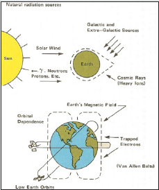
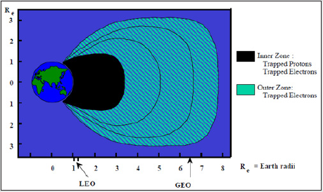
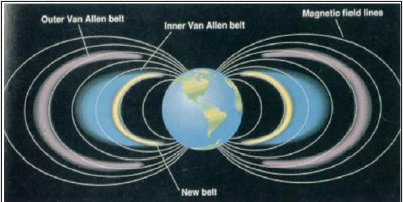
With technical progress within world of Artificial Intelligence system along with its integral sub-systems such as Machine Learning (ML) and Deep Learning (DL) [1,2], we do see a trend among companies such as Tesla, Google, and Apple as well as new startup companies pushing further and further toward next generation of automobile that driven by means of autonomy. As the next millennium coming around the corner with edge of technology pushing the envelope, we are increasingly dependent on successful and more reliable spacecraft assets such as satellite communication for our smartphone and other means of communications, Global Positioning Satellite (GPS) for our navigation, Military Satellite such as MILSTAR and overall, whether they built for military, research, or commercial missions in hand. In the 1970s and aera of Strategic Defense Initiative (SDI) know as Star Wars, the view was widely focused on the design of Radiation-Hardened (Rad- Hard) spacecraft and system in space either GEO or LEO that would become a reliable and “non-problem” that is fully functional and operational in a space radiation environment both man-made and natural one as illustrated in (Figure 1-3) through. This matter was taken under serious consideration among defense companies involved with SDI project for the survivability purpose of their space assets in process of being deployed in space with development of inherently radiation-hardened electronic components in particular, going from analog to digital from using Integrated Circuits (ICs) in form of Bipolar or CMOS [3,4]. Unfortunately, that is not the reality of today. In fact, reducing radiation effects on spacecraft systems to manageable levels is more complex than ever. The need for systems with high levels of performance has outpaced the capabilities of available rad-hard components and technology. At the same time, the demand for electronics capacity in commercial markets has greatly decreased the manufacturer’s interest in developing radhard components, driving up the cost of rad-hard parts and making them increasingly unavailable.
Radiation and What Is It?
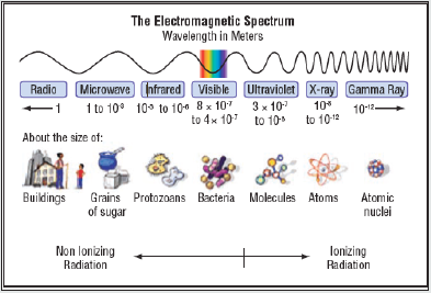
Using radiation description defined by United States (U.S.), National Aeronautics and Space Administration (NASA), we can state that, Radiation is a form of energy that is emitted or transmitted in the form of rays, electromagnetic waves, and/or particles. In some cases, radiation can be seen (visible light) or felt (infrared radiation), while other forms like x-rays and gamma rays are not visible and can only be observed directly or indirectly with special equipment. All alone these characteristic can be defined by the “Electromagnetic Spectrum” of the wavelength of these radiation waves as illustrated in (Figure 4). Although radiation can have negative effects both on biological and mechanical systems, it can also be carefully used to learn more about each of those systems. The motion of electrically charged particles produces electromagnetic waves. These waves are also called “electromagnetic radiation” because they radiate from the electrically charged particles. They travel through empty space as well as through air and other substances. Scientists have observed that electromagnetic radiation has a dual “personality.” Besides acting like waves, it acts like a stream of particles (called photons) that has no mass. The photons with the highest energy correspond to the shortest wavelengths and vice versa. The full range of wavelengths (and photon energies) is called the electromagnetic spectrum. The shorter the wavelength, the more energetic the radiation and the greater the potential for biological harm.
With movement toward space deployment assets by companies
such as Space X and Bule Origin, you do not observe any attempt
in their radiation hardening research, with their ideas of launching
roughly speaking 500 satellite around low earth orbit with next
decade. The rad-hard market share is simply too small. The
decreased support for radiation hardened component design and
technology in the military sector has compounded the problem.
Increasingly, system performance requirements must be met by
using commercial technologies that have complex responses to the
radiation environment. The Very Large Scale Integration (VLSI)
device and system trends have required increased use of radiation
management techniques, such as, the use of radiation-tolerant
components, the use of specialized shielding, system redundancy,
effects mitigation and circumvention, criticality analysis, and failure mode analysis. Also, there is a new awareness of the need
for investment in research in the area of radiation hardened
components. ICs and electronic systems must be designed to
perform under a wide variety of hostile conditions including, as
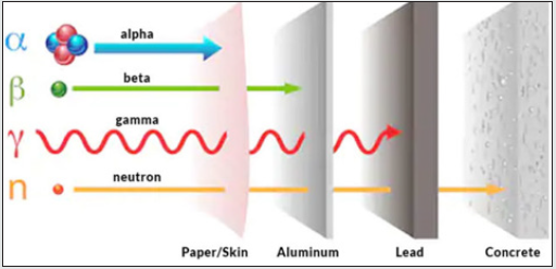
we stated both man-made and natural radiation environments. Energetic particles such as neutrons, protons, electrons, gammas,
and ions as illustrated in (Figure 5) present in the natural space
and other radiation environments can create significant damage
in semiconductor materials and devices by displacing atoms and
generating charges as the particles traverse the material.
Based on the nature of damage created by radiation effects they
are usually divided into three primary groups as:
1. Displacement Damage Effects (DDE) result from the
dislodgement of the materials mostly.
2. Total Dose effects (TDE) are those, which result from the
charge and charge center generation by ionizing radiation. These
effects are mainly responsible for degradation of devices sensitive
to the surface condition (e.g., MOS technologies).
3. Finally, there are Single Event Effects (SEEs) resulting
from the interactions with a single or a burst of high energy particles
passing through the device. For example, an energetic heavy ion can
produce displacement spikes and/or induce the so-called ionization
channels up to a few microns in diameter. Produced charge can
cause significant current and/or voltage transients which may
change the state of a circuit or even result in a permanent damage.
From past history and era of SDI (i.e., 1970’s) to present, potential
radiation environment exits for semiconductor microcircuits during
fabrication, testing and application. From processing of fabrication
of ICs and VLSIs, advanced microcircuit fabrication techniques
could be involved radiation exposure through ion implementation,
lithography and etching in batch mode or even single wafer
process through techniques such as Physical Vapor Deposition
(PVD), Chemical Vapor Deposition (CVD), Chemical Mechanical
Planarization is available to us using capital equipment’s such as
Applied Materials (AMAT)® corporation or Varian company as
well as other semiconductor manufacturers. Bear in mind that
Photolithography along with Plasma etching and Rapid Thermal
Processing (RTP) or Rapid Thermal Annealing Process (RTP) is
support of CMP can improve wafer fabrication for use in military
applications that can stand any harsh radiation environment man
or no man-made situation. Along with fabrication process, we can
implement certain testing techniques using different radiation
exposure to scan for manufacturing defects, and indirect exposure
with the use of radioactive gas for leak of junction detection and
latch up circumstance between these junctions.
With assist with Artificial Intelligence (AI) in conjunction with
Machine Learning (ML) and Deep Learning (DL) [1], we can enhance
our testing process to almost a perfection mode by collecting data
from each finished wafer coming out of such process[3-5]. The
application radiation of environments of microcircuits including
the natural space radiation environments as illustrated in (Figure
1) in above, for terrestrial satellites, the interplanetary and
planetary environments for space probes, nuclear particles from
the radioactive decay of trace elements in component package,
the nuclear environment of reactor systems, the cosmic ray
environments and the nuclear weapons radiation environments,
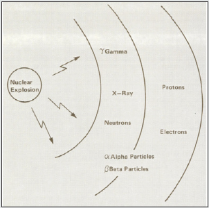
which must be considered as a military system threat as illustrated
in (Figure 6). In addition to the direct radiation environments,
electronic components must also be in a situation to be able to
tolerate electrical transients, which results from the interaction of
the radiation surrounding space with the natural environment and
systems structure accordingly as well. For example, detonation of
a nuclear weapon at high-altitude produces a layer of ionization in
the upper atmosphere that then re-radiates as an intense Electro-
Magnetic Pulse known as “High Altitude EMP”. See Table 1 for
more granular information of Nuclear Weapon Radiation Effects in
Section 2 of this paper.
The coupling of the EMP with the electronic System, then
produces electrical transients at the terminals of the components.
Component electrical overstress can also occur from interaction
of the free-field direct radiation environment and the electronic
system. For example, dielectric materials on a spacecraft will be
charged by continuous exposure to the natural space radiation
environment as it is illustrated in (Figure 1) through (Figure 3).
If a critical potential is reached, an arc discharge will occur that
couples, electrical transients into the system. Exposure of an
electronic system to a high intensity pulsed ionizing radiation
environment also produces critical electrical transients within the
system. Electrons scattered from the system structure will cause
circulating currents which couple energy into the electronics in
form of System Generated Electro-Magnetic Pulse (SGEMP), and
results in electromagnetic fields within the system structure form
of Independent Environment Monitoring Program (IEMP), which
is an environmental sampling initiative that is designed to verify
that public health and the environment around licensed nuclear
facilities are safe. Note that: System-Generated Electro-Magnetic
Pulse (SGEMP) event is a transient radiation effect produced
in an exposure to nuclear burst that can be devastating to space
assets. Low-energy X-Rays from the nuclear burst are absorbed,
are liberating free electrons, which create transient electronic
currents that deposit in electronic devices, and causing data loss,
interruption, or physical damage from electrical overstress.
The process of regulating the effects and degree of penetration
of radioactive rays varies according to the type of radiation involved.
Indirectly ionizing radiation, which includes neutrons, gamma
rays, and x-rays, is categorized separately from directly ionizing
radiation, which involves charged particles. Different radiation
shielding materials are better suited for certain types of radiation
than others, as determined by the interaction between specific
particles and the elemental properties of the shielding material.
Moreover, in the case of digital circuits, this can lead to results that
are inaccurate or unintelligible. It is a particularly serious problem
in designing artificial satellites, spacecraft, military aircraft, nuclear
power stations and nuclear weapons. Typical sources of exposure
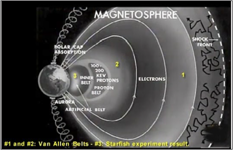
of electronics to ionizing radiation are the Van Allen radiation belts
for satellites, nuclear reactors in power plants for sensors and
control circuits, residual radiation from isotopes in chip packaging
materials, cosmic radiation for spacecraft and high-altitude aircraft
and nuclear explosions for potentially all military and civilian
electronics[3,4,6]. In summary, space radiation effects driven by
Electro-Magnetic Pulse (EMP) and Transient Radiation Effects
in Electronics (TREE) is summarized in Table 1[7]. The radiation
environment of concern consists of high energy electrons and
protons trapped in the earth’s magnetosphere as well as cosmic
rays from the solar wind and deep space. A most particular current
concern is off course, Jovian radiation environment which is critical
in the success of the NASA Galileo Mission to Jupiter r for that
matter any new space exploration by others as well., The Jovian
environment not only is including concern for high energy electrons
and protons, but also has high energy heavy particles trapped in the
planet’s magnetosphere as well [8-11].
Nuclear Weapon Radiation Effects Technology
A nuclear detonation creates a severe environment including
blast, thermal pulse, neutrons, x-ray and gamma-ray, radiation,
Electromagnetic Pulse (EMP), and ionization of the upper
atmosphere. Depending upon the environment in which the
nuclear device is detonated, blast effects are manifested as ground
shock, water shock, “blueout,” cratering, and large amounts of
dust and radioactive fallout. All pose problems for the survival of
friendly systems and can lead to the destruction or neutralization
of hostile assets. Although some Nuclear Weapons Effects
(NWE) such as blast and cratering have analogs in the effects of
conventional weapons, many NWE are unique to nuclear use. In
addition, blast and other “common” weapons effects are likely to
be much more powerful in the nuclear case than in the realm of
conventional weapons. NWE are so severe that combinations of two
or more simultaneously (as in a real event) may not add linearly,
complicating the design and construction of physical simulators or
the writing and validation of computer simulation codes[12]. Some
NWE can be modeled mathematically using powerful computers;
others, and in particular the combination of several effects, are
beyond valid analytic or numerical assessment. The only way to know if friendly systems or target assets will endure a given nuclear
attack may be to expose representative equipment to real nuclear
explosions or to construct complex simulators which reproduce a
part of the spectrum of NWE. Until the conclusion of the Limited
Test Ban Treaty (LTBT) in 1963, the United States conducted
atmospheric tests of nuclear weapons, and it was relatively simple
to include effects testing in the experiment. The scope of discussion
on nuclear weapon radiation effects is summarized as it can be seen
in Table 1. The direct radiation environment of a nuclear weapon
consists of high intensity photon and neutron pulses [13]. The
intensity, waveform and energy spectrum of the pulses are strong
functions of the system and the threat. The critical issue of interest
in this discussion is the specification of a radiation environment in
terms which can be related to simulation in laboratory radiation
environment or computer codes as they are described in next
Section 4.0 of this article.
The fundamental failure mechanism needs to be discussed
is in the context of nuclear weapon radiation effects are the P-N
junction photocurrents resulting from high intensity ionizing
radiation pulse, and permanent damage from neutron-induced
atomic displacement damage in the semiconductor crystal and
these types of discussions are beyond the scop of this article, yet
the more granular information can be found in References. [14-16]
Permanent damage effects resulting from accumulated ionization
are also a critical aspect of microcircuit hardness and have been
reviewed in reference [8]. It should be noted, however, that pulsed
ionization short-term annealing effects such as Rapid Thermal
Process (RTP) or Rapid Thermal Annealing (RTA) will be much
more sever for sub-millisecond nuclear environment than for the
slowly accumulating satellite environment. In this case, simulation
by exposure to a low-intensity source will be the best-case, rather
than the worst-case as probable for space radiation applications.
Moreover, experimental simulators of pulsed ionizing radiation
effects include a wide variety of flash x-ray machines, high energy
linear accelerators, and pulsed optical lasers. Neutron displacement
damage effects are experimentally investigated by exposure to the
environments of nuclear reactors, in the pulsed mode of operations
for the simulation of short-term annealing effects, or by pre-post
characterization to stepped, accumulated exposures for the measure
of stable damage [8]. As with space radiation effects, analytical
simulation of transient radiation effects is a critical capability for
interpreting experimental data and extrapolating experimental
results to the system environment. Accurate analytical estimates
have been developed for transient photocurrent in ideal junctions
and gain degradation in bipolar transistors which can be very useful
in the first -order correction of observed effects. More sophisticated
analytical methodologies have been developed for evaluation of
microcircuit latch-up susceptibility and with complex device models
for direct analytical simulation of non-linear circuit radiation
induced transient response. The analytical capabilities, in addition
to existing data banks, are critical supplements to experimental
simulation capability. Fore information we recommend the reader
of this short review to refer to reference [8].
Computer Codes Dealing with Radiation Effects and Hardenings
During the era of Strategic Defense Initiative (SDI) a lot of different computer codes were developed around radiation and laser hardening, by defense companies in collaboration with national laboratories as well. The following codes are mentioned in this section as part of these efforts, including one that is known as PUFF-TFT and its complementary of other codes that enhances any radiation hardening simulation either natural or man-made ones, and all these codes can be purchase from the Galaxy Advanced Engineering with their web site at www.gaeinc.com. The following codes are supporting and complementary to PUFF-TFT Version 6.0c computer code. Here we have described high level aspect of each code along with their holistic definitions wat each code is capable of handling radiation transport and X-Ray transport from 1-D, through 2-D and finally 3-D analysis not only Cold and Hot X-Ray, but in some cases to take High Energy Laser radiation into consideration some of survivability and Rad as well as Laser Hardening problems. First we start with background and history of PUFF series code and begin with PUFF66 and then go to PUFF74 and then introduce PUFF-TFT.
PUFF66
The one-dimensional Lagrangian hydrodynamics computer
program PUFF is described. The code is used primarily in the
study of X-ray effects and uses finite difference methods to solve
the equations of hydrodynamics using slab geometry and assuming
1-dimensional flow through a 1-centimeter-square pipe. The
original PUFF was a derivative of a code of the Lawrence Radiation
Laboratory (O. Nance, M. Wilkins, I. Blandford, and H. Smith, ‘Sharp,
‘ A one- dimensional hydrodynamics code for the IBM 704,’ UCRL-
5206-T, 1958).
PUFF66 was used to refer to an energy deposition code, while
P PUFF refers to a plate slap (or flyer plate) code. The two codes
are essentially the same except for the generator subroutines.
The report explains the major calculations in each subroutine and
describes all input/output variables. The subroutines are for the
generator, rezoning, editing, equation of state, and input variables.
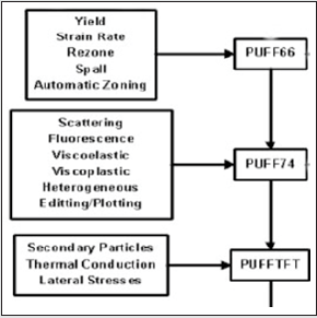
PUFF74
The PUFF74 also was branched out from PUFF66 as shown in
(Figure 7).
The PUFF74 code is a computer code which calculates stress
wave formation and propagation by numerical integration of
the conservation equations in a one-dimensional Lagrangian
coordinate system. The code uses the FORTRAN IV language.
This report presents a complete reference manual and guide for
using the code. All program and subroutines are documented.
Descriptions of the input requirements and calculated output are
included. The PUFF74 code is a computer code which calculates
stress wave formation and propagation by numerical integration
of the conservation equations in a one-dimensional Lagrangian coordinate system. The code has been under development since
1961 and has evolved from a simple hydrodynamics code to a
flexible material response code, which includes the effects of
material strength, porosity, and fracture for both homogeneous and
composite material s. The code is written in FORTRAN IV in modular
form which allows the user to conveniently add newly developed
physical models or editing capabilities. Although the code has been
developed for use at the Air Force Weapons Laboratory computer
facilities, only minor modifications would be required for use on
other computers. 130000 octal words of storage in the overlayed
version on the CDC 7600 computer.
PUFF-TFT
Historically, PUFF-TFT is derivative of PUFF74, where TFT or
Thin Film Transport capability was added to PUFF74 as further
capability and additional functionality to PUFF74. The eventual aim
was to present the AFWL with a code which formed subroutines
in the existing PUFF74 code with switchable routines, that need
only be employed when deemed necessary, e.g., on for a thin-film
package and off or most normal vulnerability problems involving
thicker layers. By editing PUFF at the cascade deposition stage (no
hydrodynamic or thermal calculations), the resulting data would
be similar to that presently obtainable from SANDYL or XRT or
later version of it, XRTH (i.e., Hydrodynamic capability was added
on to XRT), resulting data would be the overall thermomechanical
response of the system being assessed, including the consequences
of modified energy deposition in thin layers. Transport (TFT) use the
existing routine within PUFF that computes X-Ray deposition. They
reprocess these data to handle Thin Film energy sharing and, thus,
redefine the X-Ray depositions. This new deposition information is
then automatically used as input for the hydrodynamic calculations
in PUFF, in a fully coupled manner.
In review of existing other codes, we can see that, ideally ad
existing code would and should be able to compute the following
situations and topics as:
(1) X-Ray interactions to give X-Ray dose,
(2) Electron/photon cascade energy redistribution, and
(3) Thermal conductivity energy redistribution, leading to,
(4) Thermomechanical stress-wave response incorporating
(1), (2) and (3).
No previous single existing code handled all four aspects
simultaneously. However, PUFF-TFT handles topics (1) and (4),
while XRT/XRTH handles topics of (1), (2) and (3), and combination
of codes such as SANDYL and TIGERP as combined side-by-side run
handle topics (1) and (2). Then there are codes such as FSCATT
as standalone code and TRIDEP a sub-routine within PUFF-TFT,
compute X-Ray deposition in materials and incorporate the
effects on the X-Ray photons of photoelectric absorption, coherent
scattering, and incoherent Compton scattering. Thus, such codes
correctly (or to a high approximation) include the effects of
multiple photon scattering between differing layers in a mirror
package. The package may be treated as one-dimensional owing
to the large aspect ratio of mirror diameter to layer thickness.
These codes compute differential fluences ΔF, cal/cm2 (fluence in
less fluence out) over zones of differential areal mass Δσ (g/cm2)
due to all X-ray interactions. The ratio ΔF/Δσ (cal/g) is assumed to
represent the local energy deposition or dose. For bulk materials
this is a good approximation. For very thin layers it can give serious
errors in dose calculation, as explained in PUFF-TFT manual Part I.
However, When an X-ray photon is absorbed, e.g., by
photoelectric effect, it is in reality promptly replaced by a
photoelectron, leaving the absorbing atom in an excited state.
The atom relaxes to ground state by the further emission of either
fluorescent photons or Auger electrons. secondary cascade occurs.
Each secondary particle has finite energy and range over which it loses its energy to surrounding matter. Thus, the true energy
deposition in a material is the consequence of the overlapping Thus
an electron/photon . deposition profiles of the various cascade
particles, each generated at sites determined by the initial X-ray
absorptions.
SANDYL
The SANDYLE code is Monte Carlo based and can handle 1-D, 2-D, and 3-D geometries. The physics included are rigorous, allowing for correct X-Ray interactions of all types (photoelectric, Compton scattering, pair production and annihilation, fluorescence, and Bremsstrahlung). It handles X-Rays in the energy range 0.1 keV to 100 MeV. The code fully predicts secondary interactions such as photoelectron production, fluorescence, Auger electron production and Compton electron excitation, including all relative probabilities and energies. It correctly incorporates true directionality of photoelectrons relative to photon path, i.e., the Fischer and Sauter formulations, and includes Coster-Kronig autoionization effects. The code accounts for electron energy deposition using condensed Monte Carlo techniques (as in the ELTRAN code) and employs suitably modified Bethe energy-loss formulations. allowing for the interface electron/photon cascade energy redistribution effects. The code clearly handles relativistic effects.
ELTRAN
ELTRAN is an One-Dimensional Monte Carlo Electron transport code, which employs a quasi-Monte Carlo computational scheme to compute one-dimensional, electron deposition, in semi-infinite composite slabs. It has the capability of computing either the energy deposition profile distribution of stopped electrons, or the spectral properties of electrons transmitted by a thin slab, which may be solid, liquid, or gas. The incident electrons may be mono-energetic, or they may form a spectrum; they may be incident perpendicular or at an angle to the slab. ELTRAN computer code employs a quasi Monte Carlo scheme which involves calculation of the trajectory of an individual electron. This calculation is repeated until a sufficient number of electrons or case histories has been accumulated so that the user obtains the desired degree of statistical precision. Instead of considering each of the tens of thousands of individual collisions, the electron is given an incremental displacement, and the small energy loss and small effective scattering angle are computed. The electron is given additional incremental displacements until the electron is absorbed (stopped), backscattered or transmitted. Again, this incrementation is repeated for additional electrons until the desired number of case histories is run. The energy loss is computed using the continuous slowing-down approximation, with the effects of density, range straggling, and bremsstrahlung included. The scattering angle is computed by means of the Moliere multiple scattering angle distribution. an energy deposition and transport code for slab geometry which includes the effects of photoelectric absorption, fluorescence, and Compton scattering. The intensity of the secondary radiation field (scattered or fluorescent radiation) is resolved using discrete angular and energy groups. The mesh (one or more material layers) is swept alternately in the forward and backward direction until the energy remaining to be distributed is less than some specified fraction of the initial energy incident on the mesh. The motivation for using this type of numerical technique is to overcome the expense and uncertainty involved when using Monte Carlo codes. Observations indicate that results at least as accurate as those obtained with Monte Carlo codes can be obtained with substantially less computer time using the FSCATT code.
FSCATT
FSCATT is an energy deposition and transport code for slab
geometry which includes the effects of photoelectric absorption,
fluorescence, and Compton scattering. The intensity of the
secondary radiation field (scattered or fluorescent radiation) is
resolved using discrete angular and energy groups. The mesh (one
or more material layers) is swept alternately in the forward and
backward direction until the energy remaining to be distributed is
less than some specified fraction of the initial energy incident on
the mesh. The motivation for using this type of numerical technique
is to overcome the expense and uncertainty involved when using
Monte Carlo codes. Observations indicate that results at least as
accurate as those obtained with Monte Carlo codes can be obtained
with substantially less computer time using the FSCATT code.
The preceding statement is not intended to imply that all
FSCATT calculations are inexpensive. While the majority of
calculations run rapidly, increasing the number of angular groups
and energy groups used to resolve the scattered and fluoresced
energy increases the running time in a nonlinear fashion. FSCATT
is designed to allow the experienced user a great deal of latitude in
problem definition while at the same time being a fairly automatic
and simple code for the inexperienced user to operate. All of the
physical data needed for 40 elements are contained in the code as
are the data for a blackbody (Planck) spectrum. FSCATT allows for
the following radiation source options:
1. A blackbody spectrum.
2. A mixture of 1 to 10 different temperature blackbody spectra,
either:
a. distributed over 90 energy groups, each containing equal
amounts of energy, or
b. distributed over an energy group structure supplied by the user
3. A spectrum read from file.
4. Data supplied by the user consisting of points describing the
spectrum(energy, intensity) and the number of energy groups
desired between adjacent points.
5. The angle of incidence of the radiation on the slab can be
specified for any of the spectrum options.
The geometry of the code allows for the specification of 10
material layers each consisting of up to five individual constituents
(elements). In addition, the various physical processes accounted
for in FSCATT (i.e., photoelectric absorption, fluorescence, and scattering) can be suppressed by the user in individual layers, thus
decreasing the computer time required to complete a calculation.
HYPUF
HYPUF is a stress wave response code that has the ability to calculate ionization effects in high temperature, high-density plasmas. As such, HYPUF is a derivative of the PUFF66 code. HYPUF is also a code for any defense contractor having need to calculate the response of materials to radiation induced stress waves. The modification to present HYPUF code available in PC program is part of a continuing program to provide a code suitable for analysis of material interaction with X-Ray lasers and other high intensity radiation sources. Previous version of HYPUF code included automatic zoning, rezoning and spall (fracture) capabilities. The modifications in the present code include elastic-viscoplastic, Maxwell dispersion, and Bade geometric dispersion material response models, restructuring of the code to facilitate future modifications and numerous minor corrections to the equation of state and ionization equation of state subroutines. All above three models are incorporated as closely as possible to the way they were implemented in PUFF74 code. The only differences between the implementation in the two codes was that imposed by the fact that HYPUF is a temperature based rather than energy based code and that HYPUF has its equation of state package completely separate from the HYDRO routine. The elastic-viscoplastic model is an extension of the elastic-plastic model, which is used to calculate stress deviators in solid materials. In the elastic-viscoplastic model, the stress deviator can overshoot the yield surface value. The stress deviator is computed incrementally from the differential equation.
XRTH
The X-Ray Transport and Hydrodynamic known as XRTH code is developed to evaluates X-Ray deposition and its subsequent effects in one-dimensional layered media. This XRTH is particularly adapted to the analysis of heating and stress wave propagation in the coating and substrates of optical systems such as mirrors, filters, and radiators. It is written in FORTRAN 77 and is operating on a number of Operating System (OS) of different computer platforms. The first phase of XRTH consists of an X-Ray transport calculation. Up to 12 incidents or primary X-Ray beams are defined by input spectrum, time dependence, direction, and intensity. Scattering and photoelectric processes attenuate these primary beams as they traverse the material. Much of the energy lost by the primary beam may be transferred to secondary electrons, but secondary photons are also produced. These secondary photons are analyzed by a discrete-ordinates method, in which several inclination angles in both forward and backward hemispheres are established in advance, and the scattered and fluorescent radiation from each primary beam is divided into secondary beams in each of these discrete directions. Scattering and photoelectric processes are treated for the secondary photons in the same manner as for the primary beams, although the energy group structure for secondary photons is not necessarily the same as for the primary photons. The successive generations of photons produced by scattering and fluorescence are processed in turn, so that the system is solved iteratively rather than by matrix algebra. Because the optical coatings typically have thicknesses 10.0 to 10.6 cm, the electron range cannot be neglected as-in X-ray deposition calculations often employed for bulk materials. The generation and transport of secondary electrons must therefore be treated in some detail, and this is done in the second phase of the XRTH Window/PC code.
ITS/TIGERP
ITS is a powerful and user-friendly software package permitting
state-of-the-art Monte Carlo solution of linear time-independent
coupled electron/photon radiation transport problems, with
or without the presence of macroscopic electric and magnetic
fields of arbitrary spatial dependence. Our goal has been to
simultaneously maximize operational simplicity and physical
accuracy. Through a set of preprocessor directives, the user selects
one of the many ITS codes. The ease with which the make-file
system is applied combines with an input scheme based on orderindependent
descriptive keywords that makes maximum use of
defaults and internal error checking to provide experimentalists
and theorists alike with a method for the routine but rigorous
solution of sophisticated radiation transport problems. Physical
rigor is provided by employing accurate cross sections, sampling
distributions, and physical models for describing the production
and transport of the electron/photon cascade from 1.0 GeV
down to 1.0 keV. The availability of source code permits the more
sophisticated user to tailor the codes to specific applications and to
extend the capabilities of the codes to more complex applications.
Version 5.0, the latest version of ITS, contains:
a. Improvements to the ITS 3.0 continuous-energy codes,
b. Multigroup codes with adjoint transport capabilities,
c. Parallel implementations of all ITS codes,
d. A general purpose geometry engine for linking with CAD
or other geometry formats, and
e. The Cholla facet geometry library. Moreover, the general
user friendliness of the software has been enhanced through
increased internal error checking and improved code portability
There have been many people involved in the development of
the ITS codes over the years. We have undoubtedly lost track of
the contributions of some, and even if we had not, there would be
too many to list here. ITS has been assembled by borrowing and
linking algorithms from many generous sources. We are grateful to
those who have shared their methods and grateful also to the many
users who have suggested improvements over the years. The ITS
codes owe most of their development to John Halbleib. He wrote
the TIGER code and was the primary developer of the ITS codes
throughout most of their history. The original TIGER code was built
on the ETRAN code developed by Steve Seltzer and Martin Berger,
both of NIST (the National Institute of Standards and Technology).
Further collaborations with NIST, led to improvements of the
algorithms and cross sections used by ITS. Tom Mehlhorn played an important role in the first integration of the Integrated TIGER
Series.
PRONTO
PRONTO code comes in two model of 2-D and 3-D using a Lagrangian finite element and each are described here. PRONTO 2D is a two-dimensional transient solid dynamics code for analyzing large deformations of highly nonlinear materials subjected to extremely high strain rates. This Lagrangian finite element program uses an explicit time integration operator to integrate the equations of motion. Four node uniform strain quadrilateral elements are used in the finite element formulation. A number of new numerical algorithms which have been developed for the code are described in this report. An adaptive time step control algorithm is described which greatly improves stability as well as performance in plasticity problems. A robust hourglass control scheme which eliminates hourglass distortions without disturbing the finite element solution is included. All constitutive models in PRONTO are cast in an unrotated configuration defined using the rotation determined from the polar decomposition of the deformation gradient. An accurate incremental algorithm was developed to determine this rotation and is described in detail. A robust contact algorithm was developed which allows for the impact and interaction of deforming contact surfaces of quite general geometry. A number of numerical examples are presented to demonstrate the utility of these algorithms.PRONTO 3D is a three-dimensional transient solid dynamics code for analyzing large deformations of highly nonlinear materials subjected to extremely high strain rates. This Lagrangian finite element program uses an explicit time integration operator to integrate the equations of motion. Eight-node uniform strain hexahedral elements are used in the finite element formulation. A number of new numerical algorithms which have been developed for the code are described in this report. An adaptive time step control algorithm is described which greatly improves stability as well as performance in plasticity problems. A robust hourglass control scheme which eliminates hourglass distortions without disturbing the finite element solution is included. All constitutive models in PRONTO are cast in an unrotated configuration defined using the rotation determined from the polar decomposition of the deformation gradient. An accurate incremental algorithm was developed to determine this rotation and is described in detail. A robust contact algorithm was developed which allows for the impact and interaction of deforming contact surfaces of quite general geometry. Numerical examples are presented to demonstrate the utility of these algorithms. The other code that I am aware of them and have copy of the source codes and their executable of them can be purchased from Galaxy Advance Engineering (GAE) are listed as follows and more details of them can be found on GAE web site at www.gaeinc.com including the purchase price for single licenses.
a. ASTHMA 88 Aerothem Axi-Symmetric Transient Heating and Materials Ablation Code.
b. MOM Massive Off-gassing Model Code.
c. MEVDP A Primary Radiation Transport Code-Complex Geometry.
d. EDEP-1 Heavy Ion Energy Deposition Code System.
e. CASCADE Monte Carlo Simulation of the Transport of High Energy Electrons and Photons in Matters.
f. DOSFACTER Monte Carlo Simulation of the Transport of High Energy Electrons and Photons in Matters.
g. OPEX-II A radiation Shield Optimization Code.
h. SPARES A Space Radiation Environment and Shielding System.
i. SHIELDOSE Code System for Space Shielding Radiation Dose Calculation.
j. AIRDIF A Two-Dimensional Atmospheric Radiation Diffusion Code.
Conclusion
With the development of astronautic techniques, the radiation
effects on Integrated Circuits (ICs) and associated Very Large Scale
Integrated (VLSI) have been recognized by people. Environments
with high levels of ionizing Terrestrial Space Environment radiation
create special design challenges for ICs and VLSIs. To ensure the
proper operation of such systems, manufacturers of integrated
circuits and sensors intended for the military aerospace markets
adopt various methods of radiation hardening. The terrestrial
space radiation environment man-made or natural consists of high
energy electrons and protons trapped in the Earth’s magnetosphere
and in particular Van Allen Belt as well as cosmic rays from solar
wind and deep space. In addition, any nuclear detonation either
Exo-atmospheric or Endo-atmospheric makes the matter even
worst, thus either way for an orbiting space vehicle, the density
and energy spectrum of the trapped particles is a strong function
of the specific orbit such as LEO or GEO, as we;; as the activity of
the sun[8-9].
With companies such as Space X and Blue Origin in recent years
that are trying to occupy the Low Earth Orbit (LEO) with their
goal of 500 satellites within this orbit being parked, the cosmic
ray environment , on the other hand, is relatively insensitive to the
specific orbits except at relatively low altitudes, when it comes to
their digital and electronic gadget on board for either navigation
or communication purposes, in particular the share number of
them in orbit creates a redundancy safety factors. In general, the
principle density of the trapped particles is in the inner or outer
Van Allen Belts as shown in Figure-2 and now here in (Figure 8)
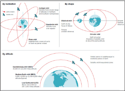
through (Figure 9). The Earth’s magnetic field has a varying effect
on shielding space radiation, depending on the mission orbit [10] as
(Figure 9,10) shows the different orbit types and their properties.
Leaving the Earth’s surface, Figure-10 shows the Low Earth Orbit
(LEO), a geocentric orbit with an altitude ranging from 0 to 2,000
km (1,240 miles). In order to keep a satellite in orbit with minimum
energy, it is crucial to eliminate atmospheric drag, so practical Earth orbits begin at approximately 167 km (100 miles) and have
an orbital period between one and two hours. LEOs are relatively
low-altitude orbits and thus the least expensive in terms of energy
expended to achieve orbit. In LEO, round-trip signal distances are
the shortest; signal communication delays are minimal, and surface
details are better resolved than for higher orbits. The orbital
periods of LEO satellites range from approximately 1 1/2 hours to a
bit more than two hours [5].
Medium Earth Orbit (MEO) is defined between LEO and
Geostationary Earth Orbit (GEO) at 35,786 km (22,236 miles). MEO
is usually used for navigation spacecraft such as Global Positioning
Satellite (GPS), communication and science observation missions.
The orbital periods of MEO satellites range from approximately
two to nearly 24 hours. Geosynchronous orbit (GSO) and GEO
both match the Earth’s rotation, and thus complete one full orbit
every 24 hours. A satellite in GSO stays exactly above the equator,
while a satellite in GEO will swing north to south during its orbit.
Any orbiting spacecraft with an altitude above GEO is considered
to be in high Earth orbit (HEO). HEOs are orbits usually reserved
for missions that need to get away from the heavy electromagnetic
traffic present in lower orbits, such as those focused on monitoring
deep space.
LEO – particularly equatorial orbits, where the magnetic
shielding effect is maximized – provides the greatest benefit in
terms of minimizing radiation effects. At higher altitudes, orbits
such as MEO or GEO, and/or highly inclined orbits or polar orbits,
the shielding provided by the Earth’s magnetic field is significantly
reduced, leading to higher particle fluxes and a higher probability
of more disruptive events. Missions with high inclinations or polar
orbits will be exposed to higher fluxes and higher energy particles
since the Earth’s magnetic shielding becomes less effective at
higher/lower latitudes away from the equator. For interplanetary
flights far from the Earth’s protective magnetic field, the spacecraft
is exposed to the high fluxes of energetic particles. Furthermore,
of particular concern to the system electronic components are
the high energy particles and resultant effects that compromise
their performance in the system. The specific high energy electron
exposure for a “typical” satellite that is orbiting under nominal
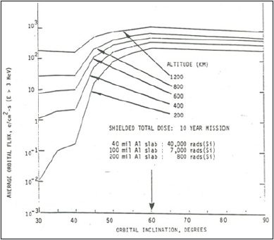
solar conditions is shown in (Figure 11). The exposure to the
integral electron flux for electrons of energies greater than 3 MeV is
in Figure-11 shown as a function of circular orbital inclination and
altitude. Degradation effects associated with the electron exposure
will accumulate for the life of the satellite. The exposure at the
internal components, however, is a function of the total material
shielding the component from the external environment.
For example, for inclination greater than 60 degrees, the electron exposure with an aluminum slab shield of 40 mils would be approximately 1.6 x 10¹² electrons/cm2 for a 10 year mission. It is important to note that the environment can be specified by the number and energy spectrum of the energy particles at the component [7]. It is also important to note that shielding of the material surrounding the component significantly reduces but does not eliminate the electron exposure. The first step in the specification of the high energy electron exposure at the component is careful definition of the external and shielded environment, for example as reference [8] and [9] by Stassinopoulos of NASA Goddard. The environmental conditions that the shielding is placed in is also important to consider. How well a material can withstand heat, if the shielding will be moved and potentially bumped and if the material must hold any structural load are all important factors in the environment that need to be considered. Shielding properties can change when put under stress or heated. Dents and damage to the material may also lessen the ability for a material to shield properly [11]. Safety is important in selecting the right shielding solutions. Leaded glass for example comes in several options including safety glass. Clear Leaded Acrylic is also a viable option to making durable clear shielding that is shatter resistant. Exposed lead may not be permitted in some scenarios due to the toxicity of lead, so polymers mixed with bismuth, tungsten or iron may be a better, non-toxic alternative. Cost is an important to consider when selecting the appropriate shielding material for a job. Lead is a very effective and inexpensive shielding material compared to materials like tungsten and could work just as well for a lot of scenarios. Related to cost, another factor that needs to be considered is the ease of shipping, handling, and installation. Choosing between installing leaded drywall or sheet lead is one example where shipping and installation need to be considered.
References
- Zohuri B, Rahmani MF (2019) “Artificial Intelligence Driven Resiliency with Machine Learning and Deep Learning Components” JCC 4(2): 1-8.
- Bahman Zohuri, Simak Zadeh (2020) "Artificial Intelligence Driven by Machine Learning and Deep Learning", Nova Science Pub Inc 455.
- Zohuri B (2021) “Application of Materials in Radiation Hardening”, Journal of Advanced Materials Science and Engineering 1 :1(4).
- Zohuri B (2021) “Materials Driving Survivability, Radiation Hardening, and Shielding of Integrated Circuits in a Radiation Environment” Lupine 4(1): 455-461.
- http://www.ti.com/radbook
- Holmes-Siedle, AG, Adams L (2002) Handbook of Radiation Effects. Oxford University Press, England.
- James P (1985) Raymond Mission Research Corporation, “Environments, Failure Mechanisms, and Simulation of Radiation Effects on Microelectronics Components”, Tutorial Short Course, IEEE 1985 Nuclear and Space Radiation Effects Conference Monterey, California.
- Stassinopoulos EG. Barth JM (1982) “Non-Equatorial Terrestrial Low Altitude Charged Particle Radiation Environment”, NASA Goddard Space Flight Center X-601: 82-89.
- Stassinopoulos EG, Barth JM (1984) “Transport and Shielding Analysis of the Non-Equatorial Terrestrial Low Altitude Charged Particle radiation Environment 1: Solar Minimum”, NASA Goddard Space Flight Center, NASA Report No. X-601-84-86.
- https://earthobservatory.nasa.gov/Features/OrbitsCatalog/
- Paul Rochus Shielding Technician, prochus@marsmetal.com.
- https://irp.fas.org/threat/mctl98-2/p2sec06.pdf
- Samuel Glasstone (1962) “The effects of Nuclear Weapons, Editor, Department of the Army Pamphlet 39-43.
- Van Lint VAJ (1980) “Mechanisms of Radiation effects in Electronic Materials, Volume I” Wiley-Interscience, John Wiley and Sons, New York, N.Y.
- Frank Larin (1968) “Radiation Effects in Semiconductor Devices”, John Wiley & sons, New York, N.Y, USA.
- Ricketts LW (1972) “Fundamentals of Nuclear Hardening of Electronic Equipment”, Wiley-Interscience, John Wiley & Sons, New York, NY.

Top Editors
-

Mark E Smith
Bio chemistry
University of Texas Medical Branch, USA -

Lawrence A Presley
Department of Criminal Justice
Liberty University, USA -

Thomas W Miller
Department of Psychiatry
University of Kentucky, USA -

Gjumrakch Aliev
Department of Medicine
Gally International Biomedical Research & Consulting LLC, USA -

Christopher Bryant
Department of Urbanisation and Agricultural
Montreal university, USA -

Robert William Frare
Oral & Maxillofacial Pathology
New York University, USA -

Rudolph Modesto Navari
Gastroenterology and Hepatology
University of Alabama, UK -

Andrew Hague
Department of Medicine
Universities of Bradford, UK -

George Gregory Buttigieg
Maltese College of Obstetrics and Gynaecology, Europe -

Chen-Hsiung Yeh
Oncology
Circulogene Theranostics, England -
.png)
Emilio Bucio-Carrillo
Radiation Chemistry
National University of Mexico, USA -
.jpg)
Casey J Grenier
Analytical Chemistry
Wentworth Institute of Technology, USA -
Hany Atalah
Minimally Invasive Surgery
Mercer University school of Medicine, USA -

Abu-Hussein Muhamad
Pediatric Dentistry
University of Athens , Greece

The annual scholar awards from Lupine Publishers honor a selected number Read More...


