


Lupine Publishers Group
Lupine Publishers
ISSN: 2641-6921
Research Article(ISSN: 2641-6921) 
Granulation of Metals as One of The Methods for Production of The Unique New Materials Volume 1 - Issue 3
Received:April 04, 2019; Published: April 26, 2019
*Corresponding author:Ivan V Kazachkov, Department of Information Technologies and Data Analysis, Ukraine.
DOI: 10.32474/MAMS.2019.01.000114
Abstract
Basics of the development and testing of the new granulation machine are presented. The production of the uniform by size and form particles (granules) cooled with a high rate, to be amorphous or close to the amorphous materials, is organized as controlled film flow and its disintegration into drops. Such granules of the given size and form are under demand in material science for creation of the new unique materials. The new patented granulation devices tested and implemented are described. The developed methods and devices can be used for production of the amorphous or close to the amorphous granules in a wide range of the given sizes, with a narrow deviation of size (max 50% from average size). There are no analogues of such granulation machines.
Keywords: Granulation Machine; Rapid Solidification; Amorphous; Film Flow; Drops; Granules
Introduction and Statement of the Problem
The problem of granulation of the materials is in focus of the scientists and engineers dealing with development of the amorphous metals with enforced charteristics for the strength and durability, as well as granules for production of materials with complex internal structure based on the same properties of components (granules). An excellent ratio of a weight to strength may help in reduction in a total weight of the multiple devices (small and big), constructions, vehicles, airplanes, and so on. The aluminium-magnesium granules are needed for space industry, the magnesium granules (coated and uncoated, size of particles over about 160μm) are used to reduce sulfur in the pig iron, in pyrotechnics, for military purposes, etc. The main concept of granulation was liquid spraying (atomization) [1], e.g. atomization of tin and solder was introduced for the manufacture of pastes for plumbing in the XIX century. In 1915, Prof. Hall (USA) patented spray nozzles for aluminium applied in explosives using the compressed air or the easily accessible steam for spraying.
The air spraying is still widely used as the cheapest method for granulation of zinc, aluminium and copper alloys at the rate of 0.5-3 tons per hour. The low-cost large-scale processing of melt is used in the metallurgical industry, especially for the high-temperature melts. One of the first attempts in granulation for improvement of the metals were the Method and apparatus for forming a powder from metals [2] (1945), Polysius Gmbh (Vorrichtung zum Granulieren von Pulver- oder Griessfoermigem Gut, 1952), Western Electric Co (Apparatus for making metal pellets, 1953), and United States Steel Corp (Disc-type balling device, 1955). Hundreds of patents appeared since 1960 from dozens of companies and engineers. The first were Ibm (Amorphous alloys and process therefor, 1964), Matsushita Electric Ind Co Ltd (Ferromagnetic materials, Magnetic permeability material, 1966), United Aircraft Corp (Process for making filamentary materials, 1966 and Electrostatic coatings, 1967), Uddeholms Ab (Method of making granulate, 1970).
Then it was continued by a number of companies: Fuji Photo Film Co., Ltd (Ferromagnetic metal powder comprising lead and method for making the same, 1974), Allied Chemical Corporation (Method of producing amorphous cutting blades, Titanium-beryllium amorphous alloys, 1975; Metallic glasses with high crystallization temperatures and high hardness, 1976), The Research Institute for iron, steel and other metals of the Tohoku University (Ironchromium series amorphous alloys, 1975), International Business Machines Corporation (Method for inducing uniaxial magnetic anisotropy in an amorphous ferromagnetic alloy, 1974; Controlled catalyst for manufacturing magnetic alloy particles with selective coerciveness, 1975), University of Pennsylvania (Method of making amorphous metallic alloys with enhanced magnetic properties using the tensile stress, 1976), Bell Telephone Laboratories, Inc. (Electric fuse, 1976). The development and production of the amorphous metal, a unique structure alloy, in which the metal atoms are randomly distributed was done by Metglas, Inc. (1970). The key to the manufacturing process is a rapid solidification of the molten alloy at a rate up to 106 oC/s. Water solidification is applied for producing the fine particles through a process of the granulation or atomization.
Atomization produces particles of size about 40mkm. Hydrometallurgy has been used for centuries in the precious metal refining but it is now widely used for the metals like Co, Cu, Ni, Ta, Nb, etc. Maximum powder sizes (250mkm) and median sizes (40-75mkm) are normally preferred. Atomization is widely used for processing aluminium, zinc and copper alloys. It allows the conversion of liquid melt to powder in one straightforward operation. Obviously, while atomization with high-pressure water is generically related to water granulation, the much higher water pressure (20-200 bar compared to the 2-6 bar for granulation) significantly affects the design of the equipment. It’s expensive to pump all the water needed to extract heat from the melt without boiling. Using special designs, to spray the melt, one can use a highpressure water stream only 2-3 times, and for cooling - additional water of low pressure. The need for increasingly better steel grade products and higher quality levels requests the raw material, such as granulated ferroalloys which has a homogenous composition, a minimum of pollutants or oxides and rapid melting properties. As many ferroalloy grades, especially low carbon grades, LC FeNi, LC FeCr, are added at the very final stages of the steelmaking process, then requirements on cleanliness become even more important due to little time for removal of impurities. The size and shape of granules also fit well to rapid and complete dissolution in the melt.
The Amorphous Metals
The amorphous metals have a unique non-crystalline structure. Their impressive physical and magnetic properties combine the strength and hardness with the flexibility and toughness, as well as some unique properties by demand. They promise reducing the operating costs and strengthening the energy conservation efforts with increasing application efficiency. Powders of amorphous metals containing the particles of 0.001 to 0.025 cm can be obtained by spraying a molten alloy into the drops of this size, and then quenching drops in a liquid coolant (water, chilled brine, nitrogen). These alloys may contain small amounts of the other elements contained in the commercial Fe or Ni alloys as the primary source of metals. Such elements as Mo, Ti, Mn, W, Zr, Hf, and Cu may be added subsequently. The thermal treatments, which often give the crystalline materials a high strength, are eliminated by amorphous metal alloys. Amorphous materials are durable, resistant to corrosion, and selected compositions of them are relatively stable to the concentrated sulfuric, hydrochloric or nitric acid, e.g. the amorphous Feg Ni P B Al is several orders of magnitude less reactive than the stainless steels with the concentrated hydrochloric acid [3].
The preferred novel compositions are characterized by the formula M Y Z [3] where M is a metal from the iron, nickel, cobalt, chromium and vanadium group, and mixtures thereof; Y is an element from the group of phosphorus, boron, and carbon, and mixtures thereof; and Z is an element from the group of aluminum, antimony, beryllium, germanium, indium, tin and silicon and mixtures thereof, and wherein the relative proportions in atomic percentages from about to 80, B from about 19 to 22, and C from 1 to 3. These amorphous metals are suitable for a number of applications, e.g. alloys with M iron (e.g. Fe P C Si Al) are of interest due to low cost and relatively high strength; Ni Fe P B Al - due to easy formation in combination with high strength and corrosion resistance; alloys with high chromium content (Cr P B Si) - due to unique hardness and resistance to corrosion. Bulk metallic glasses (BMG) are alloys that can be solidified into a diameter over 1mm without remarkable crystallization. The amorphous solid state satisfies the thermodynamic definition of a glass so that heating above a glass transition temperature leads to reaching a metastable super-cooled liquid region before crystallizing. Many methods for producing amorphous metals are known [4-9].
The material properties and manufacturing amorphous metal specimens depend on the methods, e.g. [8] granulates a jet of molten metal falling into a tank with liquid coolant. The metal jet divides into droplets in the liquid cooling bath and the droplets solidify and form the solid granules. The cooling liquid has substantially uniform flow across the tank in a direction perpendicular to the falling metal jet. The flow velocity of cooling liquid is below 0.1 m/s. The distance from the outlets of the launder to the surface of the liquid cooling bath is kept less than 100 times the diameter of the metal jet at the exit of the launder. From Swedish Patent No. 439783, to granulate FeCr, a jet is falling down into a water-containing bath, where a jet is split into granules by means of a concentrated water jet arranged immediately below the surface of the water bath. This method produces a big amount of small particles. But the risk of explosion is increased due to possibility of trapping water inside the molten metal droplets.
The first metallic glass was discovered over 50 year ago [10]. Then the amorphous metals were made in a variety of compositions, mostly fabricated as thin ribbons less than a millimeter in thickness because fast cooling rates (up to 106 oC/s) have been required for the retaining the metastable amorphous phase. Surprisengly, recently a new class of the amorphous metals was developed with the cooling rates just 1 oC/s [11]. The amorphous metals generated interest in the basic research and structural applications [12] because of their near-theoretical strength to stiffness ratios and extremely low damping characteristics [13]. A number of amorphous metals revealed high corrosion resistance explained by their structural homogeneity [12,14-17]. Cobalt is commonly used in the manufacture of WC hard metals for a variety of applications such as cutting tools, drills, seals, mining and masonry tool bits. Decrease in a size of the cobalt particles has dramatic effect on behavior of the processing of submicron WC/Co materials [18]. Generation and environmental stability (i.e. oxidation resistance) of dust (airborne particulate) have a concern when the finer cobalt powders are utilized. The cobalt powders were granulated with an organic binder to produce a free-flowing product with a reduced level of dust generation and improved oxidation resistance. The effects of granulated cobalt in the processing of superfine WC powders were examined and compared to nongranulated cobalt powders. In order to take advantage of these WC powders, finer cobalt powders must be used to ensure the production of homogeneous, high-quality WC/Co materials. The advantages of finer cobalt powders were summarized in [18, 19] as shown in the Table 1: where 400 mesh powder grades, which correspond to cobalt powders with a size of approximately 0.4, 0.8, 1.5 and 4.0mkm, respectively.
Table 1: The characteristics of cobalt powder grades studied.

Many different methods are commercially used to granulate the fine powders [20-22]. During granulation, the following forces can act on the powder to bond it together into larger granules:
a) capillary forces generated when a liquid is used to granulate a powder together; the strength of these granules is generally low;
b) adhesive bonding; a solidified binder phase adheres to the surface of the powder bonding particles together into larger granules;
c) solid bridging; the binder phase is usually an organic material (paraffin wax, PVA, etc.); the strength of granules depends upon the amount and type of the binder phase. The strength of adhesively-bonded granules is higher than the strength formed by capillary forces.
Granulation of The Middle-Temperature Melts Base on The Controlled Jet/Film Flow Disintegration into The Drops with Their Further Rapid Solidification
Our methods based on the controlled jet and film flow disintegration are based on the theory of the controlled jet/ film flow disintegration into the drops of given size and form. They are more complex but still comparably cheap and effective. These methods allow producing the small granules (particles) of a strictly defined size (in a wide range of the sizes available) but it is available only slightly over 103 oC. Over this temperature, we did not solve a problem with the durable materials for our granulation machines, for the moment. In a contrast to the aboveconsidered works by amorphous materials and granulation of the high-temperature metals and alloys, we deal with a granulation of the middle-temperature metals (Cu, Al, Pb, Mg, Zn, etc.), with the substantial request of the spherical form of particles and strictly uniform size (mainly below 1mm). The methods and devices for production the spherical granules (particles) of metals of a given size, with a high cooling rate by solidification are presented. In our experiments, the cooling rate of the drops during their solidification has been achieved up to 104 Celsius degrees per second! Such fine structure metals are amorphous or close to amorphous metals.
The idea of their creation appeared on the assessment of the iron’s hardness by Academician Ya.I. Frenkel nearly hundred years ago [23] theoretically the iron strength differs from the real one up to thousand times in some of its properties. The conventional production in metallurgy leads to a deterioration of all properties of the metals due to slow cooling of metal from its liquid to a solid state. The last is forming big crystals instead of the amorphous structure (or even fine grade crystal structure), which substantially decrease the properties of the metal.
The material science requires the amorphous or fine crystal structure particles of nearly the same size (the uniform properties) produced from liquid drops, cooled down with a high cooling rate, so that to avoid development of the big crystals, which can decrease the quality of a metal dramatically. The granular technology serves for this task, while the powder technology is quite different because deals with small particles of wide range by size and comparably low cooling rate. The uniform particles fit the best to further production of the new material because from different particles the material produced has no uniform properties and due to this can decrease the advantages of the amorphous final product dramatically. The granular technology is a contrast to the powder metallurgy, where cooling of particles of different size is usually going with a comparably low cooling rate. Therefore, the granules of a small size are normally required, except some special applications other than the ones of the material science. Big spherical granules cannot be produced this way because the big liquid drops have non-spherical form and worse conditions for the rapid cooling during their solidification. The capillary forces decrease dramatically by the growing diameter of particles over 3mm or so.
The method of controlled jet/film flow disintegration for granulation of melts
Our results in a creation of the highly efficient processes and the perspective technological devices have been based on the earlier developed theory of the parametric control of film flows, as well as on the discovered new phenomena of the controlled disintegration of film flow into the drops with a further rapid solidification of the drops [24-40]. Some of these basics are presented in the paper. The scientific novelty of this work consists in a development of the principles and the optimal regimes for production of the amorphous (or close to amorphous) granules for the creation of the super hard and the functionally unique composite metals. Different possible technical and technological applications of the developed new methods are presented and discussed.
The new theory of the parametrically controlled jet and film flows has been developed by our team at the Institute of Electrodynamics of Ukrainian Academy of Sciences [24-35]. The technological processes based on the discovered phenomena and the invented methods and devices for the materials’ granulation were patented and implemented into metallurgical and space industry. A description of the film flow granulation machine for Zink, Aluminium, Magnum (Zn, Al, Mg) and their alloys, whichhas no analogs in the world practice, is presented here. In a development of this granulation machine the following three important problems have been solved: parametric control of a disintegration of the liquid metal film flow (a dispersing knot), stabilization of the phase transition boundaries (protection of the channel walls against destruction), selection of an optimum cooling regime for the granules with achievement of a highest cooling rate for the drops during their solidification into granules. The first one was realized in a film granulation machine, while the other two have got the theoretical solution for the moment. The most important results obtained, which have been created a base for the brand new perspective granulation machines and have theoretical interest for controlling the film flows, are as follows:
A. The theory and engineering methods of the parametric excitation and suppression of oscillations in the film flow under an action of the electromagnetic fields and vibrations.
B. The theoretically predicted and experimentally tested three new phenomena of the disintegration of the liquid film flow into the drops using the alternating electromagnetic fields and vibration:
a) The resonant electromagnetic decay of a film flow into drops of strictly given size,
b) The vibration soliton-like film flow disintegration into the drops in a narrow range of the drops’ sizes (nearly 50% of the average size),
c) The shock-wave regime for the film flow’s disintegration into the micro size drops with a narrow size distribution.
C. The experimental facilities for a rapid cooling of the drops during their solidification, with up to 104 Celsius degrees per second, which allow producing the amorphous nanostructure granules for the new materials’ production with the unique properties. These results are new in a field of the metals’ granulation, which may serve for a production of the new amorphous materials, as well as for development of some materials with the unique complex structure by application of the electromagnetic control of the flow inside the liquid drops (maybe with some addings) before their solidification. It is also interesting for the other purposes, both in a theory and in practical applications. They may be useful for the scientists and engineers working in the theory of the controlled film flow, in constructing the granulation machines and dispergators for the industry. The general overview of the developed engineering solutions for the devices used in a granulation of melts obtained by the team of the Institute of Electrodynamics at the National Ukrainian Academy of Sciences under the leadership of Prof. A.F. Kolesnichenko are presented below in Figures 1 & 2 more in detail. Figure 1 presents more jet type granulation principle, while the controlled film flow granulation is shown in Figures 1a & 2 shows the semicircular flat channel with a melt 2 with alternate electric current and rotating cylinder 1 creating magnetic field, so that crossed electric and magnetic fields at the outlet from the channel results the alternative ponderomotive force with a frequency of the main first harmonic of Eigen oscillations of the jet. This allows disintegrating the jet on its first wave producing the spherical particles of equal sizes determined by the resonant frequency of oscillation of the jet’s free surface at its main (first) harmonics, which, in turn, is determined by flow velocity and diameter of the jet. Similar construction in Figure 1b was applied for the protection of the diaphragm of the diverter of experimental thermonuclear reactor tokamak. The Figure 1d presents one more version of the same principle. The method of granulation in Figure 1c is based on the electric welding of the electrode with further cooling of the drops falling down by the air flow supplied from the above of the working chamber.
These methods do not supply rapid quenching of the drops. And the method in Figure 1c is using liquid drops as a liquid metal sheet for the protection of the wall of tokamak against radiation. Figure 1e shows the vibration method for the jet created on the horizontal disk with the caves, which divide mechanically the film flow on a disk. Vibration is a control parameter for the disintegration of the series of horizontal jets on a disk regulating the vibration frequency and amplitude. Similar construction is in Figure 1g but there is mechanical smooth transformation of the vertical jet into a series of horizontal jets on a disk created by conical central part 2 of a disk 3. The vertical jet 6 is supplied from the channel 1. The melt is under alternating current 5, which interacts with its own magnetic field creating alternating electromagnetic force in resonance with the Eigen mode of oscillations of the jets 4. In a resonant regime the jets 4 are disintegrated into the equal drops 7 without remarkable energy consumption. The construction in Figure 1f uses the pulse electromagnetic induction system 1-3 having the cave surface 5 at its end, where the vertical jet is transformed in a thin film flow. The pulse operating point 4 is disintegrating this film flow into the drops falling down on the rotating cylinder cooled inside by water flow. This, this mechanism is cooling particles rapidly. But with such pulse disintegration of the film flow the size of particles is not regulated in a narrow range. The method in Figure 1h is simple and maybe used with a few different control systems for the film flow disintegration, both mechanically and parametrically with electric and magnetic fields and vibrations. A few engineering solutions for the controlled film flow disintegration into the drops of given size are presented in Figure 2, where the first two, (Figures 1a & b) are for the case of the counter current jets, which create the film flow as a results of the collision at the meeting point.
Due to hydraulic shock of two jets the film flow is developed with two free surfaces. Control of the alternating electromagnetic force by frequency and amplitude allows disintegrating the film flow in a desired regime. The upper channel 1 and the similar lower channel are connected to the source of alternating current going through the jet 2. Film flow 3 is under alternating electric current and its induced magnetic field 4, so that electromagnetic alternate force is acting on the film flow disintegrating it in a desired regime into the series of drops, which are falling down into the pool of coolant 5. In the pool of liquid nitrogen 5, the drops are rapidly solidified and then collected in its lower part as the granules. The Figures 2c-2f present the versions of the unified construction with the same method of film flow created by the hydraulic shock of the vertical jet on the horizontal disk. The schematic representation of the film flow on the vibrating disk (vibration of horizontal disk is due to vertical vibration of the shaft, on which it is placed) is given in Figure 2g And the photo of the pulse electromagnetic disintegration of the liquid gallium film flow is shown in Figures 2c & 2h) presents the combination of the two parametric control methods: electromagnetic (alternating electromagnetic force at the nozzle, where from jet is coming to the horizontal disk) and vibration (by the vibrating disk). Figure 2d shows the parametrically controlled film flow disintegration with the induction system 2, 3 shown in Figure 2f. The inductors are located over the film flow and below it. The induce alternating current in the film flow, which interacting with its own magnetic field creates the alternating pressures (forces) in the film flow to control it. Changing the frequency and amplitude of the electromagnetic forces, one can control the disintegration process of the film flow into the drops of given size. The photo in Figure 2h shows that gallium film flow in a weakly controlled vacuum chamber is prone to the chaotic Marangoni capillary forces, created by thin film flow of the oxide on the free surface of liquid metal film flow.
Figure 1: The methods of controlled disintegration of jet/film flow for granulation of metals.

Figure 2: The methods of controlled disintegration of jet/film flow for granulation of metals.

As seen from the picture, they are quite strong, so that comparably week induction system cannot control the process due to this effect. The induction system was placed to the cylindrical tight box with a diameter of 520 and 500mm high (the working chamber of facility), where the vacuum up to 0,1Pa was reached (in working state there were on average 0,4Pa). Facility was supplied with the closed liquid metal loop, pressure at the exit from the pump developed about 160kPa, thus the speed of the expiration made to 5m/s. Nozzles were of diverse caliber, easily replaced, with diameters of 2-7mm. Except the above, a few more different technical solutions were developed with diverse mechanisms of the electromagnetic and vibration disintegration of the liquid metal film flow into the drops of given size. The size of the drops obtained is regulated with the frequency of the parametric control of film flow disintegration together with some other means.
The Method OF Controlled Jet Flow Disintegration for Granulation
An operation principle of the granulation machines for electromagnetic batching of metal alloys [25-27, 32, 34] with a melting temperature approximately no more than 103 oC is based on disintegration of the free jet flow on the first harmonics of its Eigen oscillations. It is producing the metallic granules from the metal melts and alloys of the size about 2mm and over and normally cannot produce granules below 1mm. Applying the crossed electric and magnetic fields at the exit from the nozzle delivering a melt leads to the resonant regime. A frequency of thealternating ponderomotive electromagnetic force is chosen equal to a frequency of the Eigen oscillations of a jet. The permanent magnet is applied, magnetic field is created in a simplest way but can be arranged any some other method. A current in a melt at the nozzle has the industrial frequency of 50Hz but there is possibility to apply the poly-harmonic current supply as well. Many different constructions have been developed and successfully implemented in industry and research facilities. The cooling and solidification module were done depending on the granulating melt and the requirements stated to a size of particles and to a cooling rate, which determines the quality of the metal. Coolants were applied air, water, water-cooled copper plate, etc. It was also applied for the creation of the liquid metal drops curtain for the protection of the wall in the experimental tokamak as the jet’s disperser device. The electromagnetic batcher implements the controlling capillary disintegration (fragmentation) of a cylindrical jet of liquid metal in the range of 100...400 Hz (electromagnetic force has 100 Hz frequency, created by applying the electric current of 50Hz). The diameter of the metal spherical particles (granules) is determined by the resonant frequency of the jet’s free surface oscillations at the first harmonics, which is approximately ω=0.23u/d for the low viscous melts [25-27, 32, 34]. Here u is the flow velocity and d is diameter of the nozzle. A diameter of the spherical particles, which are produced due to a jet’s decay, is roughly estimated as dp=1.88d. Because the capillary forces are growing with decrease of the nozzle’s diameter (inversely proportional), the controlled disintegration of a jet is available up to the nozzle’s diameter about 1mm. Afterward, the Coanda effect makes the jet chaotically directed flow out of the nozzle. It is breaking the regime of a jet’s strictly vertical flow. In addition, even an accidental slight clogging of the melt with some impurities can also destroy the jet’s flow regime and cause the granulator to stop. Thus, the jet’s type granulators produce particles of a size over about 2 mm.
The method of the parametrically controlled film flow disintegration for granulation
Despite the above described advantage of the jet type
granulation method in getting the nearly ideal spherical granules
of the same given size, they revealed serious impediment to the size
limitation of approximately 2mm. The granular technology requires
particles below this limit, sometimes substantially below 1mm.
Therefore, the theory of parametrically controlled disintegration
of the liquid metal film flow has been developed [24,28-31,33-35].
The new methods and devices for film granulation were invented
based on the developed theory and discovered new phenomena of
the film flow disintegration [36-40]. The last ones produce granules
in the range of 0.5-1.5 from the average size, but they practically do
not have any limitations on a size of the producing granules up to
the mkm size. We have developed the theories of liquid metal film
flows and their parametric control for disintegration into particles
of given size. Diverse phenomena of the parametric excitation and
dumping of oscillations, their application especially for the case
of rapidly spreading films on the surfaces have been studied from
the beginning of 1980. The results of theoretical and experimental
investigations allowed designing and successful testing the new
prospective granulators of metals, as well as some other devices,
for the new material science and engineering. The jet and film
flows have to be considered taking into account different external
perturbations and variability of physical properties. The mono- and
poly-harmonic instability modes should be studied in linear and
non-linear approaches. The drops forming due to jet and film decay
have been studied focusing on the free surface forms developing
in time for different physical situations. The tasks on jet/film flow
control have been considered. Their applications are given in the
Table 2. The problem was stated to reveal the crucial regimes
and possibilities to control them. Since the modern technology
of physical modeling does not allow studying the evolution of the
free boundaries of jets and films effectively enough, as well as
determining the dynamic and kinematic parameters of continuous
flow (disperse flow - after decomposition), thus for these purposes
the mathematical models were developed [28,33,34]. Disintegration
of the liquid metal jet was performed by introduction of periodical
electromagnetic (or other) forces with the frequency  ,
where d0 and u0 are the diameter and velocity of a jet, respectively.
Aforementioned forces are formed for example with the interaction
of current flowing through the melt and the magnetic cross field.
The behavior of current changing in time, the form and dimension
of molten metal drops are interconnected. In order to obtain the
particles of the predetermined size and shape, the current in
metal has a series of the harmonics with the present harmonic
composition. The decomposition mode is acceptable when the
drops are formed on a distance equal to the present number of
wavelengths
,
where d0 and u0 are the diameter and velocity of a jet, respectively.
Aforementioned forces are formed for example with the interaction
of current flowing through the melt and the magnetic cross field.
The behavior of current changing in time, the form and dimension
of molten metal drops are interconnected. In order to obtain the
particles of the predetermined size and shape, the current in
metal has a series of the harmonics with the present harmonic
composition. The decomposition mode is acceptable when the
drops are formed on a distance equal to the present number of
wavelengths  , where λ is the wave length on the
decaying free jet. Thus, the position of jet decomposition is connected
to the amplitude of the disturbing electromagnetic forces at the
inputs into the nozzles. Velocity in a jet source is smaller than the
axial one, the jet swirl is absent, the jet radius is much smaller than
the length of its non-decayed part, the mode of outflow is laminar
and magnetic Reynolds number is much less than 1. The periodic
analytical solutions were found as
, where λ is the wave length on the
decaying free jet. Thus, the position of jet decomposition is connected
to the amplitude of the disturbing electromagnetic forces at the
inputs into the nozzles. Velocity in a jet source is smaller than the
axial one, the jet swirl is absent, the jet radius is much smaller than
the length of its non-decayed part, the mode of outflow is laminar
and magnetic Reynolds number is much less than 1. The periodic
analytical solutions were found as  , where
 is a relative radial deviation of a free surface from the
equilibrium position, corresponding to a cylindrical surface. The
density of a disturbed force in a jet’s source and the deformation
velocity of generatrix appearing due to this fact are connected by
the condition on the magnetic Euler number:
is a relative radial deviation of a free surface from the
equilibrium position, corresponding to a cylindrical surface. The
density of a disturbed force in a jet’s source and the deformation
velocity of generatrix appearing due to this fact are connected by
the condition on the magnetic Euler number:  . On
assuming the demanded value n, in accordance with this condition,
the current was supplied in molten metal under which the level of
sufficient disturbance for the jet decomposition was provided. In
a similar way - at the first wave-length of the disturbed jets - the
working process occurs in the MHD-granulators for technological
purposes. The appearance of oxide films on surface of the drops
of real metals in metallurgy (such as aluminum, copper, zink, etc.)
results however in removal of jet decomposition point from its
source. In this case the drops form is considerably non-spherical;
the process of decomposition appears unstable. This feature was
avoided either by decomposing of a jet in some neutral gaseous
atmosphere or by passing the current of poly-harmonic composition
through a melt. In the latter case, the correction of a particle form
has been done due to a sharp decay of the outflow velocity at the
end of a drop formation.
. On
assuming the demanded value n, in accordance with this condition,
the current was supplied in molten metal under which the level of
sufficient disturbance for the jet decomposition was provided. In
a similar way - at the first wave-length of the disturbed jets - the
working process occurs in the MHD-granulators for technological
purposes. The appearance of oxide films on surface of the drops
of real metals in metallurgy (such as aluminum, copper, zink, etc.)
results however in removal of jet decomposition point from its
source. In this case the drops form is considerably non-spherical;
the process of decomposition appears unstable. This feature was
avoided either by decomposing of a jet in some neutral gaseous
atmosphere or by passing the current of poly-harmonic composition
through a melt. In the latter case, the correction of a particle form
has been done due to a sharp decay of the outflow velocity at the
end of a drop formation.
Table 2: The tasks on jet/film flow control and their applications.

Computer simulation and experimental study of the process of drop formation
The computer simulation of the process of controlled
jet disintegration into the drops was done. The process has
considerable displaying of the inertia forces. The results of the
numerical solution of the Navier-Stocks non-stationary equations
performed by Dr. N.V. Lysak [33,34] are given below in Figure
3, where the isobars and isotachs in a drop are shown. The
calculations have been performed for a number of different values
of the ratio b of external electromagnetic force to the pressure at
the jet’s outlet (b from 40 to 0.4), for the same Ohnesorge number
 , where
  and
and  are the Weber and Reynolds
numbers, respectively. The Ohnesorge number is kinematic
parameter, which is completely determined by physical properties
of the fluid. The equation array with correspondent boundary
conditions has been solved numerically using the Arbitrary
Lagrangian-Eulerian approach (Figure 3). Electromagnetic forming
of the drop by cross field (electromagnetic) at the nozzle. It
allowed determining the evolution of free surface forms in time for
different physical situations. The created software allowed not only
computing the dynamic evolution of the drop’s free surface up to its
detachment from the vertical jet, but what is more valuable -also
compute the internal flow parameters. It allows developing the
sophisticated methods and devices for production of the complex
granules with internal filling with desired micro particles. This
method is intended for development of the granules and materials
with unique properties. As seen from the Figure 3 to the left, with
intensive electromagnetic action, the internal flow in the drop is also
intensive, while the Figure 3 to the right shows slow hydrodynamic
process inside the forming drop. The parametric control of the
size and form of the drop by disintegration of the jet together
with internal flow inside the drop promises the obtaining precise
granules by the statement, for production of the new materials with
unique properties by demand. Comparison of the model against
the experimental data shown in Figure 4 validated the model. The
filming of the drop decay’s process is shown in Figure 4 under
the analytical results. It is clearly seen that even analytical model
obtained in a linear stability theory corresponds in a first approach
to the experimental data, while the computer simulation by the full
Navier-Stokes equations in Figure 3 above is more precise.
are the Weber and Reynolds
numbers, respectively. The Ohnesorge number is kinematic
parameter, which is completely determined by physical properties
of the fluid. The equation array with correspondent boundary
conditions has been solved numerically using the Arbitrary
Lagrangian-Eulerian approach (Figure 3). Electromagnetic forming
of the drop by cross field (electromagnetic) at the nozzle. It
allowed determining the evolution of free surface forms in time for
different physical situations. The created software allowed not only
computing the dynamic evolution of the drop’s free surface up to its
detachment from the vertical jet, but what is more valuable -also
compute the internal flow parameters. It allows developing the
sophisticated methods and devices for production of the complex
granules with internal filling with desired micro particles. This
method is intended for development of the granules and materials
with unique properties. As seen from the Figure 3 to the left, with
intensive electromagnetic action, the internal flow in the drop is also
intensive, while the Figure 3 to the right shows slow hydrodynamic
process inside the forming drop. The parametric control of the
size and form of the drop by disintegration of the jet together
with internal flow inside the drop promises the obtaining precise
granules by the statement, for production of the new materials with
unique properties by demand. Comparison of the model against
the experimental data shown in Figure 4 validated the model. The
filming of the drop decay’s process is shown in Figure 4 under
the analytical results. It is clearly seen that even analytical model
obtained in a linear stability theory corresponds in a first approach
to the experimental data, while the computer simulation by the full
Navier-Stokes equations in Figure 3 above is more precise.
Figure 3: Electromagnetic forming of the drop by cross field (electromagnetic) at the nozzle.

Figure 4: Linear analytical solution for jet decay vs. experimental data.

Creation of the film flow due to hydraulic shock of the vertical jet with horizontal disk
Forming the thin film flow is done by vertical jet, which
transforms into a horizontal thin film flow due to hydraulic shock of
the jet on horizontal disk, which can be connected to the vibration
machine plate by shaft. The velocity of a jet is substantial but a disk
is immovable. For the shock of a vertical jet on a horizontal disk,
the momentum conservation law must be considered. The mass of
an amount of jet’s liquid, which is abruptly decelerated from the
high velocity of a jet to a zero velocity on immovable disk, during
small time ∆t a shock is ρc∆tS. Here ρ is density of a liquid, c is the
speed of sound in this liquid (for example, it is about 1500m/s in
water), S is a cross-section of a jet. This mass multiplied by a jet’s
velocity yields a momentum of the decelerated part of a jet due to
a shock with the disk. The momentum of the decelerated part of a
jet is equal to the impulse of force created by jet on the disk due to a
shock: PS∆t. Then P is computed as the pressure due to collision of
disk and jet. The momentum conservation equation for the shock of
the moving jet with the immovable disk is 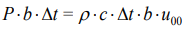 , where
  (width of a jet multiplied by a unit distance
in a direction perpendicular to the plane of the Figure y). Then
(width of a jet multiplied by a unit distance
in a direction perpendicular to the plane of the Figure y). Then
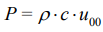 , so that it is much higher than a normal action of the
jet on a plate by a smooth flow when it is equal to a kinetic energy
of the jet, which is
, so that it is much higher than a normal action of the
jet on a plate by a smooth flow when it is equal to a kinetic energy
of the jet, which is 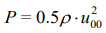 . For example, for water jet with
velocity
. For example, for water jet with
velocity  , the pressure in a shock is about 1.5*106 N/m2
, which
overwhelms about 3000 times the normal pressure from the same
jet on a plate (500 N/m2
), without shock, by a smooth flow. Now
velocity in a film flow created by a jet after its shock with a disk is
computed as follows. The momentum conservation for the film flow
is:
, the pressure in a shock is about 1.5*106 N/m2
, which
overwhelms about 3000 times the normal pressure from the same
jet on a plate (500 N/m2
), without shock, by a smooth flow. Now
velocity in a film flow created by a jet after its shock with a disk is
computed as follows. The momentum conservation for the film flow
is: 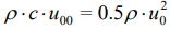 , where from follows
In the above conditions, it is 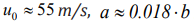 , where
from yields
, where
from yields  mm for
  mm (a jet of 1 sm width, with
velocity 1m/s creates film flow less than 0.1 mm thick, with a speed
55m/s!). The viscous dissipation of the flow energy was neglected;
therefore, these values are overestimated but still impressive big.
mm (a jet of 1 sm width, with
velocity 1m/s creates film flow less than 0.1 mm thick, with a speed
55m/s!). The viscous dissipation of the flow energy was neglected;
therefore, these values are overestimated but still impressive big.
In the film flows, the ratio of various forces significantly
depends on the film thickness, physical properties of liquid
metal, type and intensity of the external influences that define a big variety of the flow modes. A noticeable role is played by the
capillary, viscous, electromagnetic forces, etc. As mentioned above,
the moving liquid film can be disintegrated into the drops of given
size depending on a frequency of the parametric excitation (e.g.
alternating electromagnetic field), with the comparably low energy
consumption. In the other case, the system of solitons throws
off drops like a series of the unit jets do in a phase of vibration
modulation. The third case is available with a shock wave on a
jet, at the high vibration Euler numbers (10-100 depending on
the parameters). The round jet creates the radially spreading film
flow, the mass conservation of a film is 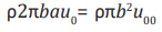 (а- film
thickness,
(а- film
thickness,  - jet radius), which yields:

where from it is seen that the radial film has the same velocity
as the flat one (created by flat jet), but its thickness in twice less.
Moreover, a film flow is spreading radially, therefore its thickness
 is decreasing with the radial coordinate growing according to
the mass conservation equation:
is decreasing with the radial coordinate growing according to
the mass conservation equation: 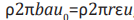 , where
  radial
coordinate (distance from the film flow origin, circle),
radial
coordinate (distance from the film flow origin, circle),  film
thickness, and
film
thickness, and  its velocity on a distance
  from origin. Then
 The momentum equation yields
 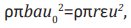 , where
from follows that a film velocity is the same as previously
, where
from follows that a film velocity is the same as previously  ,
while a thickness is varying starting from the origin
,
while a thickness is varying starting from the origin  following
the correlation
following
the correlation  thus, substantially, in a contrast to the flat
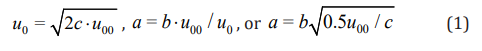
film flows. Analysis of the correlations (1), (2) for the film flow
shows that the limit value for the velocity of a jet is
thus, substantially, in a contrast to the flat
film flows. Analysis of the correlations (1), (2) for the film flow
shows that the limit value for the velocity of a jet is  , when
the model keeps valid.
, when
the model keeps valid.
The equations (1), (2) give, respectively, for the flat and radial
film flow 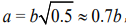 , and
, and  . Afterwards, for supersonic
jet, the flow regime is absolutely different (shock-wave jet flow),
and a film flow is not created this way. Value c is minimal in gases
(under normal conditions in the air
. Afterwards, for supersonic
jet, the flow regime is absolutely different (shock-wave jet flow),
and a film flow is not created this way. Value c is minimal in gases
(under normal conditions in the air 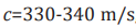 , depending on
temperature T: the higher T:, the higher the speed), the maximum in
solids (
, depending on
temperature T: the higher T:, the higher the speed), the maximum in
solids ( in steels), intermediate – in liquids (
 in water).
  is the Mach number. Flow by
  is supersonic.
The speed of sound slightly depends on the frequency in all real
physical processes as a square root of temperature (almost does
not depend on pressure and density in given gas). The following
average values c in aluminum (Al), gallium (Ga), copper (Cu), tin
(Sn), lead (Pb), zinc (Zn) are used: 4700, 2800, 3460, 2400, 1800, 2800 (m/s). Then from (2) the following approximate expressions
for the film flow velocity and thickness are written:
is supersonic.
The speed of sound slightly depends on the frequency in all real
physical processes as a square root of temperature (almost does
not depend on pressure and density in given gas). The following
average values c in aluminum (Al), gallium (Ga), copper (Cu), tin
(Sn), lead (Pb), zinc (Zn) are used: 4700, 2800, 3460, 2400, 1800, 2800 (m/s). Then from (2) the following approximate expressions
for the film flow velocity and thickness are written:

where  are the constants of the material presented
in the Table 3, where it is evident that water and mercury are close
to these indicators, while the other metal melts are very different,
especially aluminum, which has a speed of sound almost twice
higher than water. By the same parameters of a jet, the aluminum
film flow is twice faster and thinner than water film. For a radial
film, according (2), the constant
are the constants of the material presented
in the Table 3, where it is evident that water and mercury are close
to these indicators, while the other metal melts are very different,
especially aluminum, which has a speed of sound almost twice
higher than water. By the same parameters of a jet, the aluminum
film flow is twice faster and thinner than water film. For a radial
film, according (2), the constant  is twice less than that presented
in the Table 3. Velocity and thickness of the film flow depending
on the velocity of jet flow are given in the Table 4. Velocity of the
film flow is seen from the tables above depending on the velocity
of jet forming film flow. The bold values highlight exceeding
the speed of sound for a given medium. Thus, for the aluminum
melt at
is twice less than that presented
in the Table 3. Velocity and thickness of the film flow depending
on the velocity of jet flow are given in the Table 4. Velocity of the
film flow is seen from the tables above depending on the velocity
of jet forming film flow. The bold values highlight exceeding
the speed of sound for a given medium. Thus, for the aluminum
melt at  the film flow velocity is
  then
at
then
at  , respectively,
  , the impressive film
velocity, and it’s subsonic for the aluminum. In this case,
, the impressive film
velocity, and it’s subsonic for the aluminum. In this case,  and 320 respectively, which means that a film thickness of 1.6
microns
and 320 respectively, which means that a film thickness of 1.6
microns  for a jet of 10 mm thick
  at
at  , and
, and 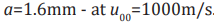 . In the latter case, this
does not seem like a film, but a simple split of the flow according to
the equations of smooth fluid flow, although a small compression of
the jet on the disk is still observed. Obviously, the micron thickness
of the film is only possible with application of the jets with a
radius of order 1 mm. The corresponding thickness of the film is
. In the latter case, this
does not seem like a film, but a simple split of the flow according to
the equations of smooth fluid flow, although a small compression of
the jet on the disk is still observed. Obviously, the micron thickness
of the film is only possible with application of the jets with a
radius of order 1 mm. The corresponding thickness of the film is
 at
at  at
at  at
at  and
and  at
at  . In the latter case,
according to (2), at a distance of 2.5 radii of the jet will be
. In the latter case,
according to (2), at a distance of 2.5 radii of the jet will be  ,
and at a distance of 25 radii of the jet, the thickness of the film
,
and at a distance of 25 radii of the jet, the thickness of the film  . Thin high-pressure jets are used, for example, in surgery as
so-called unique water scalpels with the thin water jets instead of
metal scalpels. The low limit value of the velocity of jet (corresponds
to viscous dissipation of film on disk) capable to create a hydraulic
shock is unknown for the moment. By small velocity of a jet the flow
is smoothly transformed at the disk, without hydraulic shock.
. Thin high-pressure jets are used, for example, in surgery as
so-called unique water scalpels with the thin water jets instead of
metal scalpels. The low limit value of the velocity of jet (corresponds
to viscous dissipation of film on disk) capable to create a hydraulic
shock is unknown for the moment. By small velocity of a jet the flow
is smoothly transformed at the disk, without hydraulic shock.
Table 3: The values of speed of sound and parameters for melts and water.

Table 4: Velocity u0 (m/s) and (a/b).103 for film flows depending on velocity of jet.

Film Flow Granulation Methods and Devices
The new phenomena of soliton-like and shock-wave controlled film disintegration into drops
Figure 5: The soliton-like and shock-wave regimes of the film flow disintegration under vibration.

The first new phenomenon discovered and tested by us was
the soliton-like film disintegration controlled by vibration as
shown in Figure 5a. The solitons on the disk throw off the drops
like a series of the unit jets do in a phase of vibration modulation.
When the vibration acceleration grows, the film flow is shortened
moving to the origin of the film flow. The second discovered new
phenomenon is the shock wave on a jet, at the high vibration Euler
numbers (10-100 depending on the parameters) shown in Figure
5b Correlation (3) reveals a supersonic limit for velocity of film flow
 , with a transition of a film flow through the sound
barrier
, with a transition of a film flow through the sound
barrier  under subsonic velocity of a jet:
  , and with
account of a friction on a disk – by a little prevailing of this velocity.
, and with
account of a friction on a disk – by a little prevailing of this velocity.
Electromagnetic film flow disintegration into the drops of given size
Application of the electromagnetic inductor shown in Figure 2f allows creating the running wave, which is inducing a modulated electromagnetic force in a film flow. It is capable to control the film flow, especially – in a resonance regime. The most important is not amplitude of the force but a frequency of the external action coinciding with the Eigen oscillations. Film flow is mechanically divided into the jets on a disk due to radial channels on its surface. These channels on the surface of disk are seen under inductor (the big one in Figure 6 located over disk). The Figure 6 presents resonant regime of electromagnetically controlled film flow disintegration into the drops of nearly constant size computed by the first harmonics of the Eigen oscillations of the jets on the disk
Electromagnetic inductor on the nozzle creates the running wave
where k, m are the wave numbers by coordinates  of the
cylindrical coordinate system,
of the
cylindrical coordinate system,  is the frequency of electromagnetic
field, which can be controlled by the special poly-harmonic power
supply,
is the frequency of electromagnetic
field, which can be controlled by the special poly-harmonic power
supply,  - vertical component of the strength of magnetic field,
 - its amplitude. Such electromagnetic wave induces the circle
currents in a film flow, which interaction with the field results in
the radial ponderomotive forces. The controlling electromagnetic
force in the film is modulated in the direction of the film flow.
- its amplitude. Such electromagnetic wave induces the circle
currents in a film flow, which interaction with the field results in
the radial ponderomotive forces. The controlling electromagnetic
force in the film is modulated in the direction of the film flow.
The film flow granulation machine with liquid nitrogen solidification of the drops
The schematic representation of the film flow granulation machine is given in Figure 7. The semi-industrial film flow granulator has refrigerating conditions and crystallization of drops and granules at which their adhesion is excluded. These conditions are defined by the corresponding choice of level of coolant (liquid nitrogen) in a crystallizer and its continuous circulation. Besides, are provided creation of the film ring veil of coolant improving conditions of crystallization of drops and promoting growing crystallization rate. The dispersive structure is quite uniform, especially with account of the considerable errors of experimental data connected with a non-stationary process (drift of a resonance of the vibrator at dependence on a melt flow rate). Exercising control of drift of a resonance and its automatic deduction, it is possible to narrow the dispersive structure of granules. The developed new principles of granulation allowed constructing the film MHD- and electrodynamic granulators differing significantly in the higher productivity (1-2 decimal orders) comparing to the known jet granulation machines [25-27,32,34]. They don’t have analogs in the world, substantially wider range of the producing mono-granules, and simplicity of a design and low-energy consumption. One of the semi-industrial granulators, FGA-1 (the film granulator for aluminum alloys), was successfully tested in vitro and at the enterprise. Figures 8 & 9 clearly demonstrate that the drops and granules produced are nearly uniform by their sizes. The drops of controlled size can be produced using the developed by us granulation machines for different metals. The facility was proven on a few medium-temperature melts and alloys with a melting temperature up to 103 oC and slightly higher. Granulation was prepared for special metallurgy and for production of the new materials with the unique properties. Distribution of the drops by sizes was achieved narrow, with a deviation of about 50% from the given size. For comparison, a distribution of the drops by sizes in the process of free film decay was broader than the given value 10 times and even more. The vibration granulation machine worked using the standard 10kW vibrator but with special membranes in the resonance regimes. These membranes allowed obtaining the required vibration frequency and vibration acceleration up to 2000m/s2. The electromagnetically controlled disintegration of the film flows shown in Figure 6 was done in a vacuum chamber with the nitrogen atmosphere. The weak vacuum in a chamber (1 mbar for example) did not allow working with some melts due to a very strong thin oxide film on a surface of the liquid metal film flow, which makes the process totally chaotic as seen in Figure 2h. The high cooling rate of the granules was achieved up to 104 oC/s. The construction of the liquid nitrogen cooling system contains the liquid nitrogen film flow under the liquid metal flow, which allows avoiding the crisis of heat transfer.
Figure 6: Electromagnetically controlled disintegration of gallium film flow in the resonant regime.

Figure 7: Schematic of semi-industrial film granulator for middle-temperature alloys.

Figure 8: Particles of Al produced in soliton-like regime (without separation by size) and on centrifugal granulator (to the right, particles separated in the given range of sizes).

Figure 9: Particles Zn produced in soliton-like regime on vibration type granulator.

Conclusion
Granulation technologies have specific applications, one of which is a production of the new materials from the uniform particles having the amorphous structure. Powder metallurgy has its own specific application, where the uniformity of small particles and their structure are not among the main requirements. By a development of the new materials with a structure close to the amorphous one, the main task is a cheap production of the uniform amorphous particles of the required size or with a narrow distribution by sizes (e.g. deviation from an average size 50% or so). The amorphous structure can be got by high cooling rates; therefore this task is as follows: cheap production of the nearly the same particles (granules) from the liquid metal, cooled (solidified) with the extremely high rate (we got 104 oC/s). Thus, the first one, in turn, requires starting this problem’s solution from solving a task of obtaining the uniform drops from liquid metal in a comparably cheap way. We have solved it by a development of the theory and methods of the parametrically controlled disintegration of film flows. The developed granulation technology based on the controlled film flow phenomena allow obtaining the unique amorphous and special particles (e.g. with internal filling with micro particles oriented in an electromagnetic field) for a production of the super hard metals, as well as the materials with the functionally unique properties. The known granulation machines (e.g. centrifugal) produce a wide spectrum of particle sizes and have much below cooling rate so that cannot compete with our technology. But we cannot produce granules from the high-temperature metals (steel) yet, which will be done with development of the materials working under such hard conditions.
Conclusion
- D Norval Metals and alloys water solidification a bridge from pyro- to hydro-metallurgy. The South African Institute of Mining and Metallurgy. The Third Southern African Conference on Base Metals pp. 97-106.
- (1948) HR Forton Patent US2451546. Method and apparatus for forming a powder from metals.
- H Chen , D Polk (1974) US 3856513A. Novel amorphous metals and amorphous metal articles.
- DF Carroll, Jjarvi (2001) Granulated Cobalt Powders For WC/Co Materials 15th International Plansee Seminar.
- SA Dunn, et al. in Patent US 3,658,979.
- (1948) HR Forton Patent US2451546. Method and apparatus for forming a powder from metals.
- K Forwald, R Fossheim, T Kjelland (1993) Patent US 5258053A. Method for production of granules.
- S Kavesh (1972) in a copending US. Pat. Application. 306,472.
- PÅ Lundström, C van der Westhuizen, R Hattingh, M. Görnerup (2004) Pig Iron Granulation at Iscor Saldanha Steel/ AISTech Proceedings 1: 517-524.
- W Klement, RH Willens, P Duwez (1960) Nature 187: 869.
- Peker, WL Johnson (1993) Appl Phys Lett 63: 2342.
- V Schroeder, CJ Gilbert, RO Ritchie (1998) Comparison of the corrosion behavior of a bulk amorphous metal. Scripta Materialia 38(10): 1481– 1485.
- JJ Gilman (1975) J Appl Phys 46: 1625.
- AN Mansour, CA Melendres (1995) J Electrochem Soc 142: 1961.
- M Naka, K Hashimoto, T Masumoto (1976) Corrosion. 32(4): 146-152
- TM Devine (1977) J Electrochem Soc 124(1): 1-6
- T Ramchandran, TKG Namboodhiri (1984) Corrosion 40: 73.
- DF Carroll, JE Jarvi (1999) Adv Powder MetalI Part Mater.
- DF Carroll, CL (1997) Adv Powder MetalI Part Mater.
- JK Beddow (1980) Particulate Science and Technology. New York, Chemical Publishing Co. Inc.
- CE Capes (1980) Particle Size Enlargement, Amsterdam. Elsevier Scientific Publishing Company.
- W Pietsch (1991) Size Enlargement by Agglomeration, Chichester John Wiley & Sons, 532.
- Ya I Frenkel (1946) Kinetic theory of liquids, Oxford, Clarendon Press.
- АI Glukhenkii, IV Kazachkov, AF Kolesnichenko, VP Kuchinsky, VV Malakhov (1988) Electromechanical control of the jets and films of viscous fluid and development of perspective granulators.- Kiev: In-t Electrodynamics.- Preprint № pp. 527-540.
- Yu M Gorislavets, IV Kazachkov, AF Kolesnichenko, et al. (1987) Development of the methods for MHD granulation of Aluminium alloys. Kiev: In-t of Electrodynamics Report pp. 132.
- Yu M Gorislavets, AI Glukhenkii, VM Mykhalskyi, AV Tokarevskyi (2012) Installation for electromagnetic batching of liquid metal with high productivity// J. Tekhnichna elektrodynamika p. 74-80.
- Yu M Gorislavets, VV Malakhov, AI Glukhenkii (1997) Magnetohydrodynamic installation for production of leadshot// J Tekhnichna elektrodynamika 6: 68-69.
- IV Kazachkov (1989) Parametric wave excitation and suppression on the interfaces of continua, D.Sc. thesis, Kiev.
- IV Kazachkov, AF Kolesnichenko, Pisma v Zh Tekhn, Fiziki (1991) (Letters to J. Techn. Phys.) 17: 3-40.
- IV Kazachkov (2015) Parametric Excitation and Suppression of Oscillations at the Interfaces of Continua for the Processes’ Control in Jet and Film Flows, Channel Flows with Phase Change and in Granular Media// Journal of theoretical and applied mechanics 10: 1-23.
- IV Kazachkov (2016) Technologies and Devices for Granulation Method of Amorphous Materials’ Production Based on Parametric Film Flow Decay// International Journal of Chemistry and Chemical Engineering Systems 1: 1-10.
- AF Kolesnichenko (1980) Technological MHD facilities and processes. Naukova Dumka Kiev.
- AF Kolesnichenko, IV Kazachkov, VO Vodyanuk, NV Lysak (1988) Capillary MHD Flows with Free Surfaces.
- AF Kolesnichenko, IV Kazachkov, Yu M Gorislavets (1989) Liquid metal MHD Kluwer Acad.
- А Ya Voloshyn, IN Ivanochok, IV Kazachkov, AF Kolesnichenko, VP Kuchinsky (1988) Electrodynamic excitation of the liquid film decay and development of the perspective MHD granulators.
- VO Vodyanuk, IV Kazachkov, AF Kolesnichenko, et al. (1990) USSR Patent 1476736.
- IV Kazachkov, AF Kolesnichenko, VP Kuchinsky, et al. (1992) USSR Patent 1814254.
- IV Kazachkov, AF Kolesnichenko, VP Kuchinsky, et al. (1991) USSR Patent 1570154.
- IV Kazachkov, AF Kolesnichenko, VP Kuchinsky, et al. (1989) USSR Patent 1412135.
- IV Kazachkov, AF Kolesnichenko, VP Kuchinsky, et al. (1988) USSR Patent 1184153.


-

Mark E Smith
Bio chemistry
University of Texas Medical Branch, USA -

Lawrence A Presley
Department of Criminal Justice
Liberty University, USA -

Thomas W Miller
Department of Psychiatry
University of Kentucky, USA -

Gjumrakch Aliev
Department of Medicine
Gally International Biomedical Research & Consulting LLC, USA -

Christopher Bryant
Department of Urbanisation and Agricultural
Montreal university, USA -

Robert William Frare
Oral & Maxillofacial Pathology
New York University, USA -

Rudolph Modesto Navari
Gastroenterology and Hepatology
University of Alabama, UK -

Andrew Hague
Department of Medicine
Universities of Bradford, UK -

George Gregory Buttigieg
Maltese College of Obstetrics and Gynaecology, Europe -

Chen-Hsiung Yeh
Oncology
Circulogene Theranostics, England -
.png)
Emilio Bucio-Carrillo
Radiation Chemistry
National University of Mexico, USA -
.jpg)
Casey J Grenier
Analytical Chemistry
Wentworth Institute of Technology, USA -

Hany Atalah
Minimally Invasive Surgery
Mercer University school of Medicine, USA -

Abu-Hussein Muhamad
Pediatric Dentistry
University of Athens , Greece
