


Lupine Publishers Group
Lupine Publishers
ISSN: 2641-6921
Research Article(ISSN: 2641-6921) 
Fatigue Crack Initiation in AA3004 At Elevated Temperature Using Rotating and Bending Fatigue Testing Machine Volume 1 - Issue 2
Received: December 05, 2018; Published: December 21, 2018
*Corresponding author: Rahman RA, Department of Mechanical Engineering, UET Taxila, Pakistan
DOI: 10.32474/MAMS.2018.01.000108
Abstract
The numerous failures in engineering applications occur due to fatigue, therefore, design against fatigue failure is crucial and particularly fatigue failure of engineering applications having notches or holes because almost all applications have such type of discontinuities. Once the crack initiates it is very difficult to stop it, therefore, crack initiation in different materials is vital to be designed. This work is also related to the design of crack initiation in AA 3004 aluminum alloy at elevated temperature by means rotating and bending fatigue testing machine. A favorable working temperature environment has been set by means of the 1000W electric rod. The experimental results have been plotted in the form of SN curve and a comparison has been made between crack initiation at several mechanical loadings with and without thermal loading. The mathematical model for experimental data is also reported.
Keywords: Fatigue; Initiation; Aluminium alloy
Introduction
The alloy used in this research is an emerging material for recent applications [1]. Initiation and then propagation of crack causes the fatigue failure [2]. Crack propagation is led by the edge which is a source of stress concentration and it continues till failure [3]. Notches and holes have been observed in daily engineering applications. Crack initiation starts in such type of components and structures because they experience cyclic loading [4]. The existence of notches are unavoidable in materials and structures and a detailed knowledge for fatigue failure of the notched component under mechanical and thermal loading is significant [5]. Generally, there exists the thermal environment in materials and structures, therefore, a detailed knowledge is obligatory about what happens to fatigue crack under mechanical as well as thermal loading [6]. This study reveals the experimental investigation of fatigue crack initiation in the AA3004. The thermal loading is applied with a 1000W electric rod and the temperature range has been measured using a Multi-meter with a built-in temperature sensor.
Experimental Procedure
The specimen dimensions have been adjusted as per fatigue testing machine dimensions [7]. The specimen was prepared on a lathe machine. To ensure the avoidance of residual stresses the specimen was properly cooled down and specific tool speed was maintained. The PQ-6 fatigue testing machine equipped with 0.75kW motor and 3000r/min rotation speed which examines the fatigue strength of materials while rotating and bending. The repeatedly alternating bending force from hanging loads on supporting pads creates bending stress. Such type of experimentation was performed earlier on aluminum alloy [8]. Mechanical loading (ML) is applied ranging 160N–250N with a difference of 10N. Afterward, the specimen has been subjected to the thermal loading during single step mechanical loading. Upper and lower notch lie in the range of 50 °C-100 °C. Cross section temperature ranges 50 °C-60 °C after failure. During the second phase experiments, the varying load has been applied to the specimen.
Results & Discussion
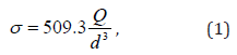
The Eq.1 has been used to convert the applied load into stress
As all the tested specimens have notches, Stress at notch is calculated by applying stress concentration factor Kt [9]
Nomenclature
Ni = No. of Cycles to initiate a fatigue crack
Np= No. of Cycles for a crack to propagate to final fracture
S2 = Low Load
S1 = High Load
Nf2= Total life at low load
Nf1= Total life at high load
N2 = Number of cycles for S2 in two-step loading
N1 = Number of cycles for S1 in two-step loading
After the effective start of crack initiation, it becomes difficult to hinder the crack growth. As the low load is applied after more than half of total fatigue life, crack was propagating in the duration of switching the load from low to high. Initially, low stress is applied in order to avoid strain hardening. If the sequence of applying stresses is changed then as a result whole initiation phase terminates in the same high level along with the starting of the next phase, complying the aim of cumulative damage accumulation. Initiation phase life is negligible, therefore, the number of cycles needed to end up the initiation phase are found from the results of experiments, in which remaining fraction of life after stress altering point “(1-x) Nf2” is compared with remaining cycles at high-stress level “yNf1”. Thus, the propagation life at low-stress level is compared with “1-y”. If the value of ‘x’ is like, the initiation period at higher load is increased [10] then it can be concluded as;
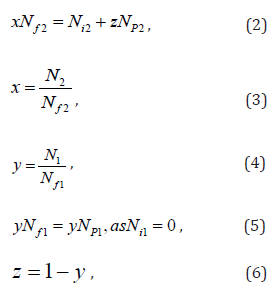
It is notified that the higher load conditions resulted in the increased crack speed and crack length at termination of initiation phase.
Hence,
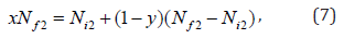
Or
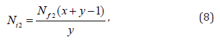
And the initiation phase life of the total life of all crack phases up to fracture [10]

Table 1 and Figure 1 show the data obtained as a result of applying only mechanical loading (ML) whereas Table 2 and Figure 2 show the data obtained as a result of applying both mechanical and thermal loadings (TL).
Table 1: Crack initiation life with only ML.

Figure 1: Load vs crack initiation life with only ML.

Table 2:Crack initiation life with both ML and TL.

Figure 2: Load vs crack initiation life with ML and TL..

Conclusion
a. The initiation phase in the form %age of fatigue life of AA3004 aluminum alloy has been calculated which is clearly mentioned in graphical results.
b. The exponential behavior is obtained for the initiation of fatigue crack during only ML.
c. The linear behavior is obtained for the initiation of fatigue during the case of both ML and TL.
d. A mathematical model for the experimental data is represented in the form of equation mentioned in graphical results.
e. The number of cycles for crack initiation decrease by the addition of thermal loading.
Acknowledgment
The author is thankful for technical and financial support provided by the University of Engineering & Technology (UET) Taxila, Pakistan.
References
- Störzel K, Bruder T, Hanselka H (2012) Durability of welded aluminium extrusion profiles and aluminium sheets in vehicle structures. Int J Fatigue 34(1): 76-85.
- Burns JT, Larsen JM, Gangloff RP (2012) Effect of initiation feature on microstructure-scale fatigue crack propagation in Al-Zn-Mg-Cu. Int J Fatigue 42: 104-121.
- Atzori B, Lazzarin P, Meneghetti G, Ricotta M (2009) Fatigue design of complex welded structures. Int J Fatigue 31(1): 59-69.
- Leidermark D, Moverare J, Segersäll M, Simonsson K, Sjöström S (2011) Evaluation of fatigue crack initiation in a notched single-crystal superalloy component Procedia Eng 10: 619-624.
- Akiniwa Y, Miyamoto N, Tsuru H, Tanaka K (2006) Notch effect on fatigue strength reduction of bearing steel in the very high cycle regime. Int J Fatigue 28(11): 1555-1565
- Zhu X, Shyam, Jones JW, Mayer H, Lasecki JV (2006) Effects of microstructure and temperature on fatigue behavior of E319-T7 cast aluminum alloy in very long-life cycles. Int J Fatigue 28(11): 1566-1571.
- Rahman RA, Juhre D, Khan U (2018) Experimental Characterization for Initiation of Crack during Fatigue Analysis of Mineralized Aluminium Alloy Under Both Thermal and Mechanical Loading on Rotating & Bending Machine. Curr Smart Mater 3(1): 1-5.
- Rahman RA, Nasir MA, Ullah M, Pasha RA, Anjum NA, et al. (2013) Demarcation of Fatigue Crack Cumulative Damage (Initiation + stage I) of Aluminum Alloy under Combined Loading. Life Sci 10: 678-683.
- Cremer M, Zimmermann M, Christ HJ (2013) High-frequency cyclic testing of welded aluminium alloy joints in the region of very high cycle fatigue (VHCF). Int J Fatigue 57: 120-130.
- Miller KJ, Zachariah KP (1977) Cumulative damage laws for fatigue crack initiation and stage I propagation. J Strain Anal Eng Des 12(4): 262-270.


-

Mark E Smith
Bio chemistry
University of Texas Medical Branch, USA -

Lawrence A Presley
Department of Criminal Justice
Liberty University, USA -

Thomas W Miller
Department of Psychiatry
University of Kentucky, USA -

Gjumrakch Aliev
Department of Medicine
Gally International Biomedical Research & Consulting LLC, USA -

Christopher Bryant
Department of Urbanisation and Agricultural
Montreal university, USA -

Robert William Frare
Oral & Maxillofacial Pathology
New York University, USA -

Rudolph Modesto Navari
Gastroenterology and Hepatology
University of Alabama, UK -

Andrew Hague
Department of Medicine
Universities of Bradford, UK -

George Gregory Buttigieg
Maltese College of Obstetrics and Gynaecology, Europe -

Chen-Hsiung Yeh
Oncology
Circulogene Theranostics, England -
.png)
Emilio Bucio-Carrillo
Radiation Chemistry
National University of Mexico, USA -
.jpg)
Casey J Grenier
Analytical Chemistry
Wentworth Institute of Technology, USA -

Hany Atalah
Minimally Invasive Surgery
Mercer University school of Medicine, USA -

Abu-Hussein Muhamad
Pediatric Dentistry
University of Athens , Greece
