Lupine Publishers Group
Lupine Publishers
Menu
ISSN: 2641-6921
Research Article(ISSN: 2641-6921) 
Carbon Fiber Pipes Characteristics Research Under cyclic pressure action Volume 2 - Issue 1
Kopei BV1*, Man’ko TA2 and Romenska OP3
- 1Ivano-Frankivsk National Technical University of Oil and Gasst, Ukraine
- 2Oles’ Honchar Dnipro National University, Ukraine
- 3State Enterprise “Design Bureau” Youzhoe” named after MK Yangel, Ukraine
Received: September 20, 2019; Published: September 27, 2019
*Corresponding author: Kopei BV, Ivano-Frankivsk National Technical University of Oil and Gasst, Karpatskaya, 15, Ivano-Frankivsk, 76019, Ukraine
DOI: 10.32474/MAMS.2019.02.000129
Abstract
The question of the possibility of using carbon fiber pipes based on carbon fiber UKN / 5000 (traditional and modified by atmospheric plasma treatment in an acrylic acid environment) as a material of pipelines for the oil industry is considered. The use of carbon fiber pipelines will significantly reduce the weight of the product and increase its reliability during operation. Experimental studies of the strength of carbon fiber pipelines with an internal working pressure of up to 7.5 MPa at a load of 10,000 cycles were carried out. The object of study is the pipeline elements in the form of a pipe with metal bushings at the ends. With the help of metal bushings, samples of the carbon fiber pipeline elements were installed in a laboratory stand to simulate the effect of internal working pressure on the deformation features of the specimen structure. In this case, as a liquid for the creation of internal pressure in the tests the formation water from the oil field at normal temperature (T = 20°C) was used. In order to predict the maximum recuperation of the pipeline made of carbon fiber, internal pressure tests were performed before failure. It is concluded that the efficiency of using carbon fiber for the production of pipelines of the oil assortment is very high. When using modified CFRP, the strength of the oil pipeline element is 20% greater than when using traditional UKN / 5000 carbon fiber as a carbon fiber filler.
Keywords: Oil Pipeline; Carbon Fiber; Plasma; Pressure; Strength
Actuality of the Work
The oil industry operates a large number of pipelines and oil products, which often fail due to the corrosive action of corrosive media, such as process or well production fluids. They have a heavy weight and significantly increase the load on the main oil equipment [1]. In order to improve the economic indicators of oil production in difficult conditions, it became necessary to create new pipelines and products of the oil assortment [2-3]. Currently, glass fiber based polymer composite material (PCM) is increasingly being used to create new pipelines. The use of fiberglass pipes in comparison with traditional metal pipes has several advantages, the main of which are low density and corrosion resistance, which allows increasing the service life of the product. It is known that carbon fiber plastics have the highest specific strength characteristics at low density. Therefore, it is of great interest to develop technology for the production of pipelines made of them [4-8]. This will significantly reduce the weight of the product and increase reliability during operation. This work aims to confirm the possibility of application in the petroleum industry in the production of oil the carbon fiber pipelines on the basis of commercial low-modulus carbon fiber UKN / 5000, modified by plasma treatment in an acrylic acid environment.
Material and Results of the Research
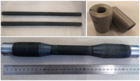
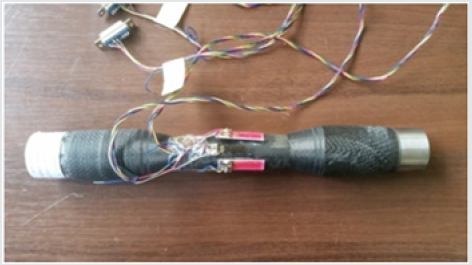
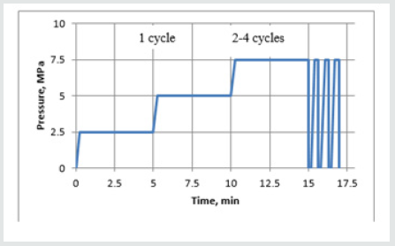
The object of the study are the elements of the oil pipeline made of carbon fiber based on the original carbon fiber brand UKN / 5000 and modified carbon fiber of the same brand atmospheric plasma treatment in an environment of acrylic acid with an epoxy matrix consisting of resin with epoxy base Araldite LY 1135, Accelerator 960, and hardener Aradur 917 (Huntsman) (Figure 1). To confirm the possibility and feasibility of replacing of existing materials used in the manufacture of pipelines in the oil industry (steel and fiberglass pipes) to composite material made of carbon fiber modified by plasma treatment in an environment of acrylic acid and epoxy binder modified by plasma treatment in an environment of acrylic acid and an epoxy binder Huntsman the hydraulic tests with internal pressure Pp = 7.5 MPa were carried out to 10,000 cycles - the life of the pipeline. The purpose of these tests was to evaluate the characteristics of the material under the exploitation conditions modeling. Reservoir water at normal temperature (T = 20°C) was fed into the pipeline element by the hydraulic system of the laboratory stand, which is shown in (Figure 2), as a liquid for the internal pressure set during the tests. Due to the fact that the deformation that occurs during their loading is an important parameter in the study of the characteristics of the elements of the oil pipelines, the movement of the material in the axial direction and in the circumferential direction after each load cycle was recorded in the work with the use of strain gauges. (Figure 3) shows an element of an oil pipeline with strain gauges. The oil pipeline elements were loaded stepwise in 2.5 MPa increments and held for 5 minutes. (Figure 4) shows a graph of stepped pressure up to 2.5 MPa, 5 MPa and 7.5 MPa during the first cycle. All subsequent cycles (up to 10,000) were performed without shutter speeds, except for every 50 cycles, at which the shutter speed was 5 min. at a pressure of 7.5 MPa.
Figure 2: Schematic of a laboratory bench to simulate the effects of internal working pressure.
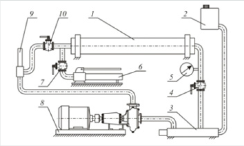
1 - element of the pipeline, 2 - expansion capacity, 3 - electric heater, 4, 7, 10 - high pressure valve, 5 - pressure gauge, 6 - high pressure pump, 8 - pumping unit, 9 – thermometer
Figure 5: Graph of relative deformations of an oil pipeline element in longitudinal and transverse directions under pressure loading.
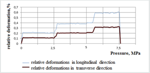
During the loading, the values of pressure change, and the magnitude of relative deformations were recorded. (Figure 5) presents a graph of relative deformations for the first load cycle of an oil pipeline element made of modified carbon-plastic material under the pressure of 7.5 MPa. The readings of the relative deformations of the oil pipeline elements from the original and modified CFRP are close in magnitude and correspond to the following values: at an internal pressure of 2.5 MPa, the relative deformation of the oil pipeline elements is 0.1% in the transverse direction and 0.2% in the longitudinal direction. When the internal pressure is increased to 5 MPa, the relative deformation increases to 0.2% in the transverse direction and 0.4% in the longitudinal direction. At a maximum internal pressure of 7.5 MPa, the relative deformation is equal to 0.3% in the transverse direction and 0.6% in the longitudinal direction.
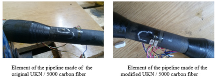
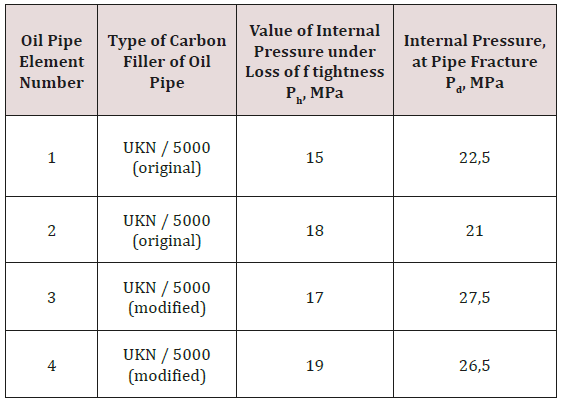
As a result of loading, the loss of tightness and destruction of the material was not detected. It is established that the elements of the pipeline withstand 10000 cycles of loading with internal pressure equal to 7.5 MPa. After cycle testing at 7.5 MPa, the pipeline elements were brought to destruction. (Figure 6) shows the elements of the pipelines that have been cycled and destroyed as a result of the internal pressure rising to the maximum. The parameters at which the elements of the pipeline lost their tightness and collapsed are presented in (Table 1).
Table 1: Values of internal pressure recorded in the loss of tightness and destruction of oil pipeline elements.
Conclusions
Based on the studies of the characteristics of carbon fiber plastic elements of oil pipelines in conditions simulating operational, it was shown that the elements of the oil pipeline made of carbon fiber based on modified atmospheric plasma treatment with acrylic acid carbon fiber UKN / 5000, were destroyed at a pressure of 26.5 to 27.5 MPa, which is 20% higher than the pressure at which the elements of the CFP oil pipeline were destroyed based on the UKN / 5000 original carbon fiber. The efficiency of the application of CFRPs, based on modified atmospheric plasma treatment with acrylic acid carbon fiber UKN / 5000 for the production of oil pipeline elements, has been confirmed.
References
- Kopey BV (2016) Repair of pipelines with polymer composite bandages. Kopey BV & Kuzmin OO (Eds.), Oil and Gas Equipment Series. Forte Symphony, Ivano-Frankivsk, Ukraine, pp. 324.
- Kopey BV, Arkhirey MM, Vengrynyuk TP (2010) Application of composite materials in oil production complex. Scientific Bulletin of the National Technical University of Oil and Gas 1(23): 68-76.
- Kopey BV, Naida AM, Kopey WB (2006) Determination of residual life of oil and gas pipelines with composite bandages. Oil and Gas Exploration and Development 1(18): 33-36.
- Kopey BV, Foundling AM (2006) Residual life strengthened by composite pipe joints with defects. Scientific Bulletin of the National Technical University of Oil and Gas 1(13): 59-65.
- Kopey BV, Naida AM, Kopey VB, Razgonyuk VV, Roizman VP, et al. (2006) Technique for estimation of strength of composite bandages of steel pipelines by the method of strain gauge and acoustic emission. Methods and devices of quality control 16: 28-32.
- Kopey BV, Ivasyshyn MV (2006) A method of manufacturing a polymeric bandage in the repair of pipelines. Utility Model Declaration.
- Panasyuk VV (2006) Mechanics of destruction and durability of materials. K Scientific thought. T.10: Strength and Durability of Oil and Gas Equipment. Pokhmursky VI & Kryzhanovsky EI (Eds.), Lviv-Ivano- Frankivsk, GV Karpenko Institute of Physics. National Academy of Sciences of Ukraine, IFNTUNG, Ukraine, pp. 1193.
- Kopey VB, Kopey BV, Nayda AM Determination of the residual life of pipelines with defects after their repair by composite bandages. Quality management in the oil and gas complex pp. 26-28.

Top Editors
-

Mark E Smith
Bio chemistry
University of Texas Medical Branch, USA -

Lawrence A Presley
Department of Criminal Justice
Liberty University, USA -

Thomas W Miller
Department of Psychiatry
University of Kentucky, USA -

Gjumrakch Aliev
Department of Medicine
Gally International Biomedical Research & Consulting LLC, USA -

Christopher Bryant
Department of Urbanisation and Agricultural
Montreal university, USA -

Robert William Frare
Oral & Maxillofacial Pathology
New York University, USA -

Rudolph Modesto Navari
Gastroenterology and Hepatology
University of Alabama, UK -

Andrew Hague
Department of Medicine
Universities of Bradford, UK -

George Gregory Buttigieg
Maltese College of Obstetrics and Gynaecology, Europe -

Chen-Hsiung Yeh
Oncology
Circulogene Theranostics, England -
.png)
Emilio Bucio-Carrillo
Radiation Chemistry
National University of Mexico, USA -
.jpg)
Casey J Grenier
Analytical Chemistry
Wentworth Institute of Technology, USA -
Hany Atalah
Minimally Invasive Surgery
Mercer University school of Medicine, USA -

Abu-Hussein Muhamad
Pediatric Dentistry
University of Athens , Greece

The annual scholar awards from Lupine Publishers honor a selected number Read More...


