Lupine Publishers Group
Lupine Publishers
Menu
ISSN: 2637-4692
Research Article(ISSN: 2637-4692) 
Cephalometric Landmark of a Midsagittal Plane of the Temporomandibular Joint in the Structure of Diagnostic Criteria for Temporomandibular Disorders Volume 1 - Issue 5
Oleg V Slesarev1* and IV Bayricov1
- 1Federal State Educational Institution of Higher Education, Samara State Medical University of the Ministry of Health of the Russian Federation, Russia
Received: March 13, 2018; Published: March 19, 2018
Corresponding author: Oleg V Slesarev, Federal State Educational Institution of Higher Education, Samara State Medical University of the Ministry of Health of the Russian Federation, Russia
DOI: 10.32474/MADOHC.2018.01.000121
Abstract
The purpose of this study was to establish a methodology for determining the midsagittal plane of the temporomandibular joint (TMJ) via the cephalometric landmarks in the structure of diagnostic criteria for temporomandibular disorders.
Study Design: Cephalometry of 20 human skulls was obtained. Targeted linear tomography of the TMJ was obtained in a lateral projection. Statistical processing included descriptive methods. Frequencies ofthe level ofthe midsagittal plane ofthe temporomandibular joint are presented.
Results: Using cephalometry, we found the midsagittal plane of the frontal process of zygomatic bone (lateral orbital wall) to correspond to the midsagittal plane of the TMJ, parallel to the midsagittal plane of the skull. The lateral orbital wall of the skull was projected onto the lateral rim of the angle of the eye. The distance between lateral orbital rims was the distance between midsagittal planes of the TMJ heads. To check cephalometric results, we used the method of targeted linear TMJ tomography. According to anatomical landmarks, the depth of the tomographic slice at the midsagittal plane of the TMJ level was defined. In total, 176 patients were examined, and 604 tomograms were studied. Images of excellent and good quality were obtained in 94.2% of cases. The depth of tomographic slices in 86.7% of studies ranged from 2.0 to 3.0cm (in 42.2% of observations, 2.5cm; in 21.6% of observations, 2.0cm; in 22.9% of observations, 3.0cm).
Conclusion: The lateral orbital wall can be used as a cephalometric landmark defining the midsagittal plane of the TMJ. The resulting landmark makes it possible to determine the individual depths of tomographic slices, to calculate the distance between heads of the mandibular jaw, and to plan treatment in reconstructive maxillofacial surgery, orthodontics, and orthopedics.
Keywords: Temporomandibular joint; Tomography of the temporomandibular joint; Cephalometry; Diagnostic criteria for temporomandibular disorders
Introduction
The diagnostic criteria for temporomandibular disorders (DC/ TMD) are reliable tools in all phases of patient supervision. In the structure of the DC/TMD, TMJ imaging methods are presented in the third group of the first part [1]. Today, the development of technology for the visualization of TMJ structures supersedes the clinically proven expediency of expensive research, which, in this clinical context, does not necessarily increase the level of clinically relevant information, in addition to demonstrating the present level of technical capabilities of the equipment, and does not increase our knowledge about the extent of natural influences of the morphological status of TMJ structures on etiology or TMD pathogenesis [2]. As noted by Ohrbach and Greene [3], the complex TMJ imaging techniques (magnetic resonance tomography and cone-beam computed tomography), in accordance with generally accepted procedures, should be used only when they are likely to have a significant effect on the formulation of a diagnosis and the management of clinical problems.
An unjustified use of expensive research, in addition to not bringing relief to the patient, establishes a sense of hopelessness, because it has been shown that, in 20% of cases, the chronic course of TMD is closely related to cognitive behavioral patient status. Analysis of clinical X-ray data has shown that the TMJ tomography method remains relevant in view of its diagnostic adequacy and affordability. According to research [4-8] a slice depth of from 1.0 cm to 4.0 cm is recommended. In routine studies, a standard slice depth for imaging the TMJ is difficult to obtain, and pathological changes in the contours of the facial skull and soft tissues of the temporal and parotid-masticatory areas defined by the standard depths result in a loss in search accuracy.
Even the use of palpable lateral TMJ head contour as a guide is not exempt from the need for exploratory sampling, because the lateral-medial condyle head size varies from 17 to 24mm [9]. Correct visualization data analysis for the TMJ is possible only in standard imaging protocol conditions. The basis of imaging protocol is a standard cephalometric landmark that defines the midsagittal plane of the TMJ, by which an individual tomographic slice level is set, allowing for a correct analysis of the data and comparison with those from other studies of the radiological anatomy of the TMJ. The objective of this study was to substantiate the method for determining the midsagittal plane of the TMJ by cephalometric landmark in the structure of the diagnostic criteria for temporomandibular joint disorders.
Materials and Methods
Cephalometry of 20 human skulls obtained from the anatomical museum of the Department of Normal Anatomy of SSMU was carried out. The midsagittal plane of each skull was determined by anatomical landmarks: palatine suture of the maxilla, nasal bone, and cranial vault. The skulls were positioned on a lined transparent solid substrate. The anatomical structures studied were oriented so that their midsagittal lines coincided with the marking on the substrate, and then moved in parallel from the midsagittal plane of the skull, laterally toward the glenoid fossa of the temporal bone plane on the substrate. Notes were made of guidelines on the skull, which was turned over along with the substrate from the base to the vault, secured, and compared with the landmarks on the substrate. The planes of section passing through the glenoid fossa of the temporal bone were projected onto the outer contours of the facial bones of the skull. In total, 176 patients were examined by targeted linear tomography of the TMJ in side view, with the individual anatomical landmarks.
Each patient's head was placed in a lateral projection relative to the plane of the table, with its midsagittal plane strictly parallel to it, and the horizontal physiological plane perpendicular to it. The depth of slice was determined from the palpated lateral margin of the orbit. The central beam was directed 1.0cm above and anterior to the external auditory canal. The focal length of the tube was 100cm. A 13x18 cm cassette was located in the transverse direction. On one tape, two images of the TMJ were made consecutively, in the centric occlusion and at maximum mouth-opening. The depth of the investigated layer was recorded in terms of a tomographic series. Physical and technical imaging conditions were: tube voltage of 57 to 63 square meters; current strength of 60 to 100 mA; focal length of 110 to 120cm; shutter speed of 2 sec; and 30° angle of displacement of the tube during tomography. In total, 604 TMJ tomograms were obtained. Statistical processing included descriptive methods. Frequencies of the levels of the midsaggital plane of the TMJ were presented. The study was approved by the ethics committee of the Federal State Educational Institution of Higher Education "Samara State Medical University" of the Ministry of Health of the Russian Federation.
Results and Discussion
Long-term comparative TMJ visualization data analysis has demonstrated significant restrictions on the use of transpharyngeal and transcranial X-rays for the purpose of panoramic orthopantomography [10]. In difficult clinical situations that require expert-level solutions, including avoiding perforation and disc dislocation, magnetic resonance tomography allows for all elements of the TMJ to be studied. Aquilano et al. [11], Fava and Preti [12] and Petersson [13] have reported that transcranial radiography of the TMJ presents significant projection distortion, determined by the direction of the main X-ray beams; therefore, the visible relief of the glenoid fossa is in fact a combination of lateral and medial condylar processes of the walls of the head or the front and back walls of the glenoid fossa. In this case, the path of the rays must be clearly directed along the pole of the condyle, which is extremely difficult to perform methodologically without search images.
Habets and co-workers [14] illustrated how panoramic radiography, as opposed to lateral tomography, can be used to assess the joint spaces and anatomical characteristics of the bone ratios of elements, and the resulting image of the upper surface of the joint head is in fact a slice of the medial part of the condylar process. Okeson [15] demonstrated that only tomography in the lateral projection allows for visualization of the TMJ with minimum distortion, providing a workable image. Thus, to neutralize the projection distortion to the maximum, one must identify and use the available anatomical landmarks that allow for determination of the midsagittal plane of the condylar process head of the mandible and glenoid fossa. Based on such landmarks, we are able, without specific search sampling, to identify the depth of a tomographic slice and define the distance between the midsagittal plane of the right and left articular condylar process heads. This will allow for the controlled, laterally or medially, slice level movement on anatomical landmarks, regardless of the types of racial characteristics of the skull shape or pathological deformation.
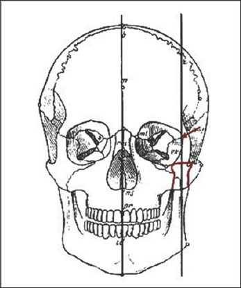
To determine the individual anatomical landmarks on the outer contours of the skull, the projection of which would coincide with the midsagittal plane of the condylar process head of the mandible, we conducted an analysis of 20 human skulls from the archives of the Department of Normal Anatomy of the Samara State Medical University. The analysis was carried out taking into account the data from several fundamental studies [16-18]. The ratio of TMJ elements to anatomic details of the facial skull was studied, in particular, with the frontal process of the zygomatic bone (Figure 1). In the two objects of the plane of the lateral edge of orbit (frontal process of the zygomatic bone) that coincided with the midsagittal plane of the glenoid fossa, the deviation of said plane at 1 mm was noted in 5 cases, and in two observations was 2 mm into the medial or lateral side from the center of the glenoid cavity.
Figure 1: Construction of cephalometric skull planes. Midsagittal plane of the skull and frontal process of the zygomatic bone coincide with the midsagittal plane of the condylar process of the lower jaw.

Only in the two objects was a significant deviation of the plane of the lateral margin of the orbit from the center of the glenoid cavity determined, by 4 mm to the medial side. It can be concluded that the sagittal plane of the head coincides with the sagittal plane of the lateral wall of the orbit. This was the reason the palpable lateral edge of the orbit was used as an individual anatomical landmark for selection of the depth of the tomographic slice at TJ imaging [19]. Thus, the midsagittal plane of the glenoid fossa of the temporal bone, articular condylar process head, and frontal process of the zygomatic bone are parallel to the midsagittal plane of the skull. Based on cephalometric data, we have developed and justified a method for determining the midsagittal plane of TMJ elements when imaging by the targeted linear tomography of individual anatomical landmarks.
TMJ imaging is carried out in the following manner. The study begins with the sighting of the left TMJ tomography. Patient placement is standard, as for linear TMJ tomography that is, in the prone position with arms extended along the body, the head in the left lateral position, and the face level with the table surface, to the scale of the tomographic ruler for readout [20]. The sagittal plane of the head is strictly parallel to the tabletop, and the frontal plane of the head is strictly perpendicular to the plane of the table. In case of difficulties with the placement of the patient (short neck, shoulder girdle, deformation of the facial skull, post-traumatic swelling of soft tissues of the face, etc.), a flat corrective stand with a height of 1 cm is placed under the patient's head, thereby aligning the head position relative to the table plane. On the 13x18 cm film, disposed transversely with respect to the table, two images of the temporomandibular joint are obtained: in the position of centric occlusion and at maximum mouth-opening.
The non-operating half of the tape is covered by a lead- impregnated rubber plate. The centre of the working cassette is located in the center of the table. The central beam is directed at a point 1.0 cm above and anterior to the external auditory meatus. Palpation is used to define the lateral wall of the patient's orbit, which usually coincides with the lateral edge of the visible corner of the eye. A light tomograph targeted scale device for readout of levels of the investigated layer from the surface of the table is combined with the plane of the fixed lateral wall of the left orbit. The first joint imaging is carried out in the position of centric occlusion [21]. The film cassette is then shifted, with respect to the central beam, to the second working half, and the second image is made at the maximum opening of the mouth under the same conditions.
Tomography of the right TMJ can be performed without changing the patient's position on the X-ray stand. In this case, the light tomograph targeted scale device is raised to the level of the plane of the lateral wall of the right orbit. However, if the distance between the studied layer and X-ray film is increased, an image of bony elements of the TMJ will be somewhat increased and less crisp. Therefore, it is more expedient to carry out study of the right TMJ after rotating the patient's head in the right side view at the slice depth obtained by the imaging of the left TMJ. It is necessary to control the rate of slice by measuring the distance from the deck of the table to the right lateral wall of the orbit (visible corner of the eye),by means of a triangle or a ruler. In post-traumatic edema of the soft tissue or bone deformities of the facial skull on the right, the depth of the studied layer can also be established with the use of a ruler or a triangle. The resulting figure is recorded on a tomograph scale.
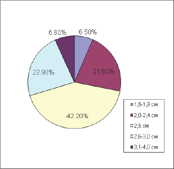
All 176 patients were examined by the method of targeted linear functional tomography with individual anatomical landmarks. The resulting 604 tomograms of the temporomandibular joint in a state of habitual occlusion and at maximum mouth-opening were studied. In terms of the tomographic ruler scale, the depth of the studied layers from the surface of the table ranged from 1.5 to 5.5cm. In 21% of cases, the study was carried out with height supports from 1.0 to 3.0 cm. Patients with severe post-traumatic edema of the soft tissues of the face were included in this group, as were those with post-traumatic deformities of the skull and facial features of the constitutional structure of the body. Tomograms of excellent and good quality were obtained in 93.8% of the surveyed persons (165 patients) (Figure 2).
Figure 2: Distribution of tomograms of TMJ by the quality of the image criteria.

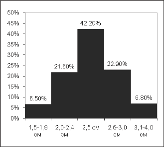
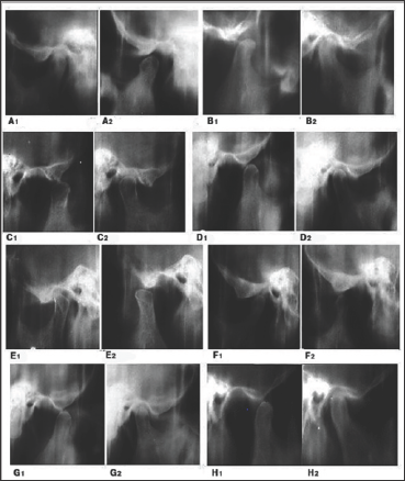
Reduced image quality was caused by a fuzzy hit in the joint slice, or by movement of the patient's head at a joint imaging, or by errors in the selection of physical and technical conditions for imaging. In 86.7% of cases, tomograms of excellent and good quality were obtained at the anatomical depth of 2.0 to 3.0 cm (Figure 3). All slice depth indicators corresponded to the level of the lateral wall of the orbit position above the X-ray deck tripod, and, in cases where the stand was used, the deduction of its height from the tomographic ruler indicator was taken into account. On the tomograms obtained, all bony components of the joint, X-ray joint space, and location of the articular heads in dental occlusion and at maximum mouth-opening are clearly visualized (Figure 4).
Figure 3: Frequencies of the level of depth of tomographic slice of TMJ, determined by an individual anatomical landmark.

Figure 4: Target linear tomography of a TMJ in a lateral projection in position of closed mouth- A1; B1; C1; D1; E1;F1; G2 И H2 (tooth rows in contact in an intertubercular position, an articular head is in the glenoid fossa of the temporal bone) and at the maximum possible abduction of the mandible from a intertubercular position A2; B2; C2; D2;E2; F2; G1 И H1 (articular head is at the top of the articular tubercle). Level of tomographic slice coinciding with the level of a midsagittal plane of a TMJ: A1-2 - 2.0 cm; B1-2 - 2.2 cm; C1-2 - 2.5 cm; D1-2 - 2.75 cm; E1-2 - 3.0 cm; F1-2-3.5 cm; G1-2 - 4.5 (with a support in height of 2.0 cm); H1-2 -5.0 cm (with a support in height of 3.0 cm).

Conclusion
Available anatomical landmarks of the projection of the midsagittal TMJ plane were defined by a method of cephalometry allowing for the individual depth of the alleged tomographic layer to be established by TMJ imaging at routine patient admission by means of targeted linear tomography. Further, in the planning of occlusal therapy according to the type of reorganization method, the distance between the centers of the mandibular jaw heads can be determined for the calculation and simulation of occlusal plane relief. The ratio of projections of the cephalometric planes of skull bones was studied. It revealed that the midsagittal TMJ cephalometric plane in all cases coincides with the midsagittal plane of the frontal process of the zygomatic bone, which forms the anterior lateral wall of the orbit.
Consequently, the lateral wall of the orbit may be used with certainty as a cephalometric point for defining the midsagittal plane of the TMJ. Use of the methodology for determining the midsagittal plane of TMJ elements by cephalometric landmarks allows for standardization of analyses of radiological anatomy of the TMJ in the structure of the DC/TMD, to determine the depth of individual tomographic slices, and to calculate the distance between the centers of the mandibular jaw heads when treatment is planned.
References
- Ahmad M, Hollender L, Anderson Q, Kartha K, Ohrbach R, et al. (2009) Research diagnostic criteria for temporomandibular disorders (RDC/ TMD): development of image analysis criteria and examiner reliability for image analysis. Oral Surg Oral Med Oral Pathol Oral RadiolEndod 107(6): 844-860.
- Busato A, Vismara V, Bertele L, Zollino I, Carinci F (2010) Relation between disk/condyle incoordination and joint morphological changes: a retrospective study on 268 TMJs. Oral Surg Oral Med Oral Pathol Oral Radiol 110(3): e34-e40.
- Ohrbach R, Greene C (2013) Temporomandibular joint diagnosis: striking a balance between the sufficiency of clinical assessment and the need for imaging. Oral Surg Oral Med Oral Pathol Oral Radiol 116(1): 124-125.
- Khvatova VA (1996) Diagnosis and treatment of functional occlusion disorders. Nizhniy Novgorod (in Russian), Russia.
- Rabukhina NA (1988) Radiographic examination in cases of traumatic injuries of facial skull bones.Vestnikrentgenol 4: 71-77 (in Russian).
- Kishkovskiy AN, Tyutin LA, Esinovskaya GN (1987) Positioning atlas for radiographic examinations. Medicina (in Russian), Leningrad, Russia.
- Shekhter IA, VorobevYI, Kotel nikov MV (1968) Atlas of radiographs of teeth and jaws in normal and pathological conditions. Medicina (in Russian), Moscow, Russia.
- Rabukhina NA, Chuprynina NM (1991) X-ray diagnosis of maxillofacial diseases. Medicina (in Russian), Moscow, Russia.
- Lang J, Oder M Uber die Biomorphose der Mandibula. Gegenbaurs morphol Jahrb 130(2): S185 (in German).
- Wise MD (2005) Failure in the restored dentition: management and treatment. Azbuka, V1 (translation by A. Ostrovskiy) (in Russian), Moscow, Russia.
- Aquilano S, Matterson S, Holland G, Phillips C (1985) Evaluation of condylar position from temporomandibular joint radiographs. The Journal of Prosthetic Dentistry 53(1): 88-97.
- Fava C, Preti G (1988) Lateral transcranial radiography of temporomandibular joints. Part II. Image formation studies with computerized tomography. The Journal of Prosthetic Dentistry 59(2): 218-227.
- Petersson A (1988) what is an optimal temporomandibular joint radiograph? In: Clarc T, Solberg WK, eds. Perspectives in Temporomandibular Joint Disorders. Quintessence Publishing Co, Chicago, USA, p. 59-65.
- Habets L, Begur J, Jemetiez Lopez V (1989) The OPG: an aid in TMJ diagnosis. A comparison between lateral tomography. Journal of Oral Rehabilitation 16(4): 401-406.
- Okeson JP (2003) Management of Temporomandibular Disorders and Occlusion. Mosby, Philadelphia, USA.
- Miyashita K (2012) Atlas of cephalometric radiography. Azbuka, (translation by A. Ostrovskiy) (in Russian), Moscow, Russia.
- Tvardovskaya MV (1972) On relation of mandibular angle to some dimensions of cerebral and facial cranium (in Russian) 62: 74.
- Bonevolenskaja JD (1972) About morphological elements of longitudinal cranial diameter. Arhivanatomii gistologiiijembriologii (in Russian) 62: 60-65.
- Poljarush NF, Slesarev OV, Poljarush MV Bjulleten izobretenij, Patent 2177722 (in Russian).
- Galhardo AP, da Costa Leite C, Gebrim EM, Gomes RL, Mukai MK, et al. (2013) The correlation of research diagnostic criteria for temporomandibular disorders and magnetic resonance imaging: a study of diagnostic accuracy. Oral Surg Oral Med Oral Pathol Oral Radiol 115(2): 277-284.
- Avdeev GA (1965) Cranial tomography. Medicina (in Russian), Moscow, Russia.

Top Editors
-

Mark E Smith
Bio chemistry
University of Texas Medical Branch, USA -

Lawrence A Presley
Department of Criminal Justice
Liberty University, USA -

Thomas W Miller
Department of Psychiatry
University of Kentucky, USA -

Gjumrakch Aliev
Department of Medicine
Gally International Biomedical Research & Consulting LLC, USA -

Christopher Bryant
Department of Urbanisation and Agricultural
Montreal university, USA -

Robert William Frare
Oral & Maxillofacial Pathology
New York University, USA -

Rudolph Modesto Navari
Gastroenterology and Hepatology
University of Alabama, UK -

Andrew Hague
Department of Medicine
Universities of Bradford, UK -

George Gregory Buttigieg
Maltese College of Obstetrics and Gynaecology, Europe -

Chen-Hsiung Yeh
Oncology
Circulogene Theranostics, England -
.png)
Emilio Bucio-Carrillo
Radiation Chemistry
National University of Mexico, USA -
.jpg)
Casey J Grenier
Analytical Chemistry
Wentworth Institute of Technology, USA -
Hany Atalah
Minimally Invasive Surgery
Mercer University school of Medicine, USA -

Abu-Hussein Muhamad
Pediatric Dentistry
University of Athens , Greece

The annual scholar awards from Lupine Publishers honor a selected number Read More...


