Lupine Publishers Group
Lupine Publishers
Menu
Research ArticleOpen Access 
An Experimental Study of a Multi-Axis Generator Volume 1 - Issue 5
Min Chie Chiu1*, Ying Chun Chang1, Ho Chih Cheng2 and Tan Cheng Tsao1
- 1Department of Mechanical and Materials Engineering, Tatung University, Taiwan, ROC.
- 2Department of Intelligent Automation Engineering, Chung Chou University of Science and Technolog, Taiwan, ROC.
Received: July 04, 2022 Published: July 19, 2022
Corresponding author: Min Chie Chiu, Department of Mechanical and Materials Engineering, Tatung University, Taiwan , ROC
DOI: 10.32474/JBRS.2022.01.000125
Abstract
In daily life, many devices, including U-bike bicycle and flying wheel in gym, can convert vibrational mechanical energy into electrical energy. The electrical generation power generations are generally classified into the electromagnetic induction type and the piezoelectric type. The electromagnetic induction type is found to have a best power generation voltage in a low frequency environment. Therefore, based on the electromagnetic induction type, a multi-axis power generator used in a low-speed environment has been introduced and assessed in this paper. In this study, according to Faraday’s law and Lenz’s law, the characteristics of the magnetic attraction between the magnets are used and instead of the springs, so that the magnets will move in the way of pistons between the pipes. The electromagnetic induction power generation device has a simple structure which is capable of generating a high voltage at a low rotation speed and is easy to obtain. In this study, there are three kinds of power generation devices invented, including a two-axis, a three-axis, and a four-axis electricity generation device. The voltages generated at the respective rotation speeds of each type has been compared and evaluated. Consequently, a four-axis power generation device is found to be capable of generating a high voltage at a low speed. The maximum peak voltage of 21.2 volts and the electric power of 71.54 watts are obtained at a speed of 160 RPM. The four-axis power generation device is the most excellent power generation capability among the three power generation devices.
Keywords: Electromechanical Generator; Multi-Axis; Magnet; Rotation
Nomenclature
This paper is constructed on the basis of the following notations:
T: time period (s)
N: number of coilers turn
ε: induced electrical voltage (Volt)
Φ: the magnetic flux (Wb)
ΔΦ: variation of the magnetic flux (Wb
Introduction
Many energy extraction methods such as the piezoelectric, electromagnetic, magneto-strictive, and electrostatic transducer types have been developed [1,2]. Recently, a vibration-based generator using electromagnetic principle has been widely explored [3-7]. In addition, because of the huge progress in the semiconductor field, MEMS [8] were widely developed. Huang et al. [9] developed a MEMS-based generator using the sea wave in 2017. Their study indicated that an electrical power of 68.9μW will be produced via the sea wave with the actuating frequencies of 0.6 Hz~1 Hz. According to Santosh Kulkarnir [10], the electrical power of an electromagnetic type generator reached 0.59 μW. In order to improve the electricity, Serre et al. [11] increased the number of the induction coiler. And El-Hami et al. [12] enhanced the electricity by enlarging the reciprocating displacement of the generator. Some electromagnetic generators [13,14] using multi-layer coiler were proposed. In addition, a generator with multiple magnetic poles was proposed by Pan and Wu [15]. Because of no need of specific frequency actuated at the generator, the multi-pole generator will be more convenient in practical application [16]. Even though the electromagnetic generators do not require to run at a specific frequency, the research of generator always focus on the situation of high-speed rotation. As the generator design by Raisigel et al. [17], the rotation speed of the generator was at 400 RPM. Also, from the research of generator design by Arnold et al. [18], the rotation speed of the generator was at 350 RPM. However, for most of rotating machine, the low frequencies are almost located within 40 RPM~ 200 RPM. Because some of the exercise, such as the bike or the flying wheel, have a system’s frequency of 40 RPM~ 200 RPM, how to transform the kinetic energy to the electrical energy by using the electromagnetic generators is the main issue in the paper. In order to develop a low-frequency generator, three kinds of power generation devices, including two-axis, three-axis and four-axis, are proposed and experimentally assessed in this study.
Design of the Vibration-based Mechanism for Electromagnetic Generators
The mechanism of multi-axis generator is shown in Figure 1. The allocation of the magnet is also illustrated in Figure 2. According to Faraday’s law of electromagnetic induction, the electrical voltage will be induced when the magnetic flux (Φ) varies. The induced electrical voltage (ε) is
ε=-N ΔΦ/Δt (1)
where ΔΦ is the variation of the magnetic flux and N is the number of coilers.
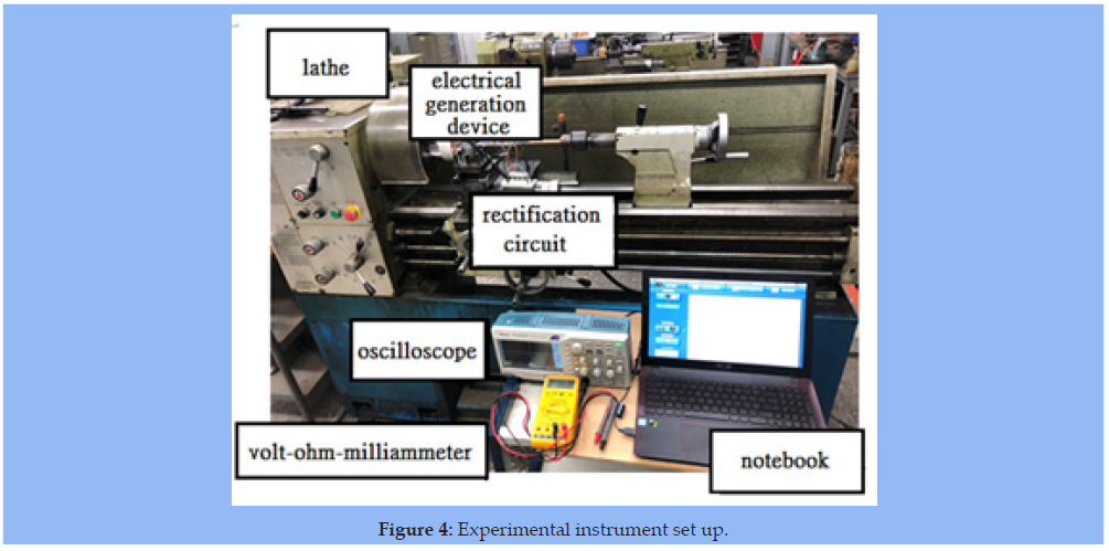
As indicated in Figure 2 in order to generate continuous electricity, the N pole and the S pole of the magnets are crossbedding. In order to sum up the current from different flowing direction, a current filtering device shown in Figure 3 is adopted. In addition, an experimental instrument of actuating the generator and measuring the induced electrical voltage is set up and depicted in Figure 4. The flow diagram in electricity generation and measuring process is demonstrated in Figure 5.
Two-axis Generator
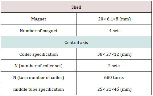
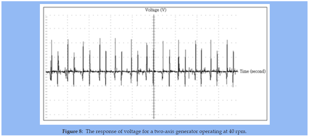
The mechanism of the two-axis generator using one N pole and one S pole is shown in Figure 6. As indicated in Figure 7, two sets of coilers surrounding around two tubes are fixed on the central port of the generator. The specification of the two-axis generator is depicted in Table 1. Two free magnets (with different poles) at one end of the generator will be triggered to move forward and backward via the magnetic attraction force and repelling force when on set of magnets (one N pole and one S pole) fixed at the other end of the generator rotates. First, the two-axis generator is triggered by using a rotation speed of 40 RPM via a lathe. The induced electrical voltage is shown in Figure 8. Similarly, the induced electrical voltage is shown in Figures 9-12 when using a rotation speed of 80 RPM, 120 RPM, 160 RPM, and 200 RPM, respectively. In addition, the induced electrical voltage of the twoaxis generator at various operating speeds is illustrated in Table 2. And, the induced electrical current of the two-axis generator at various operating speeds is also shown in Table 3.
Three-axis Generator
The mechanism of the three-axis generator using two N poles and one S pole is shown in Figure 13. Similarly, as can be seen in Figure 14, three sets of coilers surrounding around three tubes are fixed on the central port of the generator. The specification of the three-axis generator is depicted in Table 4. Three free magnets (two N pole and one S pole) at one end of the generator will be triggered to move forward and backward via the magnetic attraction force and repelling force when one set of magnets (one N pole and two S poles) fixed at the other end of the generator rotates. First, the three-axis generator is triggered by using a rotation speed of 40 RPM via a lathe. The induced electrical voltage is shown in Figure 15. Similarly, the induced electrical voltage is shown in Figures 16- 19 when using a rotation speed of 80 RPM, 120 RPM, 160 RPM, and 200 RPM, respectively. In addition, the induced electrical voltage of the three-axis generator at various operating speeds is illustrated in Table 5. And, the induced electrical current of the three-axis generator at various operating speeds is also shown in Table 6.
Four-axis Generator
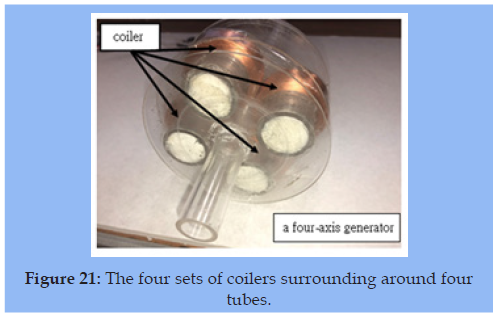
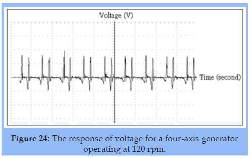
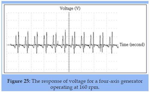
The mechanism of the four-axis generator using two N poles and two S poles is shown in Figure 20. The N pole and S pole will be located in a crisscross form. Similarly, as can be seen in Figure 21, four sets of coilers surrounding around four tubes are fixed on the central port of the generator. The specification of the four-axis generator is depicted in Table 7. Four free magnets (an interlacing of two N poles and two S poles) at one end of the generator will be triggered to move forward and backward via the magnetic attraction force and repelling force when one set of magnets (two N poles interlocked with two S poles) fixed at the other end of the generator rotates. First, the four-axis generator is triggered by using a rotation speed of 40 RPM via a lathe. The induced electrical voltage is shown in Figure 22. Similarly, the induced electrical voltage is shown in Figures 23-26 when using a rotation speed of 80 RPM, 120 RPM, 160 RPM, and 200 RPM, respectively. In addition, the induced electrical voltage of the four-axis generator at various operating speeds is illustrated in Table 8. And, the induced electrical current of the four-axis generator at various operating speeds is also shown in Table 9.
Results and Discussion
Results
Two-axis Generator
To investigate the influence of generated electrical voltage with respect to various rotation speeds, five kinds of rotation speeds (40 RPM, 80 RPM, 120 RPM, 160 RPM, and 200 RPM) are selected as the parameter. The experimental results are depicted in Figures 8-12 and Tables 2-3. Figures 8-12 and Tables 2-3 show that based on the same magnetic field of a two-axis generator, the induced electrical voltage will change if the rotation speed varies. As can be seen above, the value of electrical voltage will be the largest one when the rotation speed is tuned to 120 RPM-160 RPM.
Three-axis Generator
Similarly, to investigate the influence of generated electrical voltage with respect to the rotation speed, five kinds of rotation speeds (40 RPM, 80 RPM, 120 RPM, 160 RPM, and 200 RPM) are also chosen as the parameter. The experimental results are obtained and plotted in Figures 15-19 and Tables 5-6. Figures 15- 19 and Tables 5-6 reveal that the induced electrical voltage of the two-axis generator will reach the maximum when the rotation speed is adjusted to 120 RPM-160 RPM.
Four-axis Generator
Similarly, to investigate the influence of a four-axis generator’s generated electrical voltage with respect to various rotation speeds, five kinds of rotation speeds (40 RPM, 80 RPM, 120 RPM, 160 RPM, and 200 RPM) are also chosen as the parameter. Experimental results show in Figures 22-26 and Tables 8 & 9 reveal that the induced electrical voltage of the four-axis generator will reach the maximal value when the rotation speed is adjusted at 120 RPM-160 RPM.
Discussion
As discussed above, for three kinds of multi-axis generators (a two-axis generator, a three-axis generator, and a four-axis generator), the value of the induced electrical voltage will be the largest one when the operating speed reaches 120 RPM. Also, the time period with respect to the rotating speed at various types of generators is investigated and shown in Figure 27 and Table 10. As indicated in Figure 27 and Table 10, the time period is inversely proportional to the rotation speed. In addition, both the two-axis generator and the four-axis generator have the same T & rotation-speed curves. Moreover, the comparison of the peak electrical voltage with respect to the rotating speed at various types of generators has been performed and shown in Figure 28 and Table 11. As can be seen in Figure 28 and Table 11, the peak electrical voltage of the four-axis generator is superior to that of other generators. Similarly, the comparison of the electrical current with respect to the rotating speed at various types of generators is performed experimentally. Results in Figure 29 and Table 12 indicate that the four-axis generator has the largest electrical current than others. In addition, the maximum peak voltage of 21.2 volts and the electric power of 71.54 watts are obtained at a speed of 160 RPM. Furthermore, a comparison of the electrical power with respect to the rotating speed at various types of generators is also experimentally assessed and shown in Figure 30 and Table 13. Figure 30 and Table 13 indicate that the four-axis has the largest induced electrical power than others two generators.
Figure 27: The comparison of the time period with respect to the rotating speed at various type of generators.

Figure 28: The comparison of the peak electrical voltage with respect to the rotating speed at various types of generators.

Figure 29: The comparison of the electrical current with respect to the rotating speed at various types of generators.

Figure 30: The comparison of the electrical power with respect to the rotating speed at various types of generators.

Table 11: The peak value of electrical voltage with respect to the rotation speed at three kinds of generators.

Considering a commercial product of electrical generator (a xero dynamo brand) shown in Figure 31, the mechanism of the xero dynamo wheel set generator is illustrated in Figure 32. The comparison of the electrical voltage between the four-axis generator and the current commercial generator (xero dynamo wheel type) is also experimentally assessed and shown in Figure 33 and Table 14. As indicated in Figure 33 and Table 14, the induced electrical voltage of the four-axis generator is higher than that of the xero dynamo wheel set generator when the operating speed is within 40 RMP – 160 RPM. However, the induced electrical voltage of the four-axis generator is lower than that of the xero dynamo wheel set generator when the operating speed is at 200 RPM and above. Moreover, as can be seen in the Figure 33 and Table 14, the efficiency of electricity performance for a four-axis generator is obvious when the operating is getting lower.
Figure 33: The comparison of the electrical voltage between the four-axis generator and the current commercial generator (xero dynamo wheel type).t generator.

Table 14: The comparison of peak electrical voltage between the four-axis generator and the xero dynamo wheel set generator at various rotation speeds.

Conclusion
The goal of this paper is to develop a multi-axis electromagnetic generator. The free magnets have been attracted and repelled to move forward and backward along the tubes when an array of the magnets fixed on the other end of the generator is rotated. The magnetic flux will change, and the induced electrical voltage is then occurred. On the vibration basis, three kinds of the multiaxis generators, including a two-axis generator, a three-axis generator, and a four-axis generator, are experimentally explored. Experimental result reveals that a four-axis generator has the best electrical power. Also, the induced electrical power will be the largest when the rotation speed reaches 120 RPM to 160 RPH. The four-axis generator is also compared to the commercial generator, a xero dynamo wheel set generator. As can be seen in the result, the induce electricity of the xero dynamo wheel set generator is proportional to the operating speed. However, the value of the electrical voltage is smaller than that of the four-axis generator when the operating speed is below 160 RPM. Result also indicates that the related induced electrical voltage with respect to the fouraxis generator and the xero dynamo wheel set generator is 20 (V) and 8 (V) when the rotation speed is at 40 RPM. And the related induced electrical voltage with respect to the four-axis generator and the xero dynamo wheel set generator is 21 (V) and 18 (V) when the rotation speed is at 160 RPM. It is obvious that the four-axis generator has higher electricity efficiency than the xero dynamo wheel set generator when the frequency of the triggering force is in lower status. Consequently, the four-axis generator can be suitable for the energy regeneration of the vibrational device which has the low frequency.
References
- Mitcheson PD, Green TC, Yeatman EM, Holmes AS(2004) Architectures for vibration-driven micropower generators. Journal of Microelectromechanical Systems 13(3): 429-440.
- Mitcheson PD, Yeatman EM, Rao GK, Holmes AS, Green T C (2008) Energy harvesting from human and machine motion for wireless electronic devices. IEEE 96(9):1457-1486.
- Chiu MC, Chang YC, Yeh LJ, Chung CH (2012) Optimal Design of a Vibration-Based Electromagnetic Energy Harvester Using a Simulated Annealing Algorithm. J of Mechanics 28(4): pp. 691-700.
- Chiu MC, Chang YC, Yeh LJ, Chung CH, Chu CS (2014) An Experimental Study of Low-frequency Vibration-based Electromagnetic Generators, Advanced Materials Research. 918: 106-114.
- Chiu MC, Chang YC, Yeh LJ, Chung CH (2016) Numerical Assessment of a One-Mass Spring-Based Electromagnetic Energy Harvester on a Vibrating Object. Archives of Acoustics 41(1): 119-131.
- Chiu MC, Karkoub M, Her MG (2017) Energy Harvesting Devices for Subsea Sensors. Renewable Energy 101: 1334-1347.
- Chiu MC, Chang YC, Yeh LJ, Chung CH (2018) Optimization of a Two-Mass Vibration-Based and Electromagnetic Energy Harvester Using Simulated Annealing Method, J. of Low Frequency Noise. Vibration and Active Control 37(1): 90-106.
- Park JC, Bang DH, Park JY (2010) Micro-fabricated electromagnetic power generator to scavenge low ambient vibration. IEEE Transactions on Magnetics 46(6): 1937-1942.
- Hwang WS, Ahn JH, Jeong SY, Jung HJ, Hong SK, etal. (2017) Design of piezoelectric ocean-wave energy harvester using sway movement. Sensors and Actuators A: Physical260: 191-197.
- Beeby SP, Torah RN, Tudor MJ, Glynne-Jones P, O'donnell T, etal. (2007) A micro electromagnetic generator for vibration energy harvesting. Journal of Micromechanics and microengineering 17(7): 1257.
- Serre C, Pérez-Rodríguez A, Fondevilla N, Martincic E, Martínez S, et al. (2008) Design and implementation of mechanical resonators for optimized inertial electromagnetic microgenerators. Microsystem Technologies 14(4-5):653-658.
- El-Hami M, Glynne-Jones P, White NM, Hill M, Beeby S etal. (2001) Design and fabrication of a new vibration-based electromechanical power generator. Sensors and Actuators A: Physical 92(1-3): 335-342.
- Holmes Andrew S, Guodong Hong, Keith R Pullen (2005) Axial-flux permanent magnet machines for micropower generation. Journal of microelectromechanical systems14(1): 54-62.
- Hosseini Seyed Mohsen, Mojtaba Agha-Mirsalim, Mehran Mirzaei (2008) Design, prototyping, and analysis of a low-cost axial-flux coreless permanent-magnet generator. IEEE transactions on magnetics 44(1): 75-80.
- Pan CT, Wu TT (2007) Simulation and fabrication of magnetic rotary microgenerator with multipolar Nd/Fe/B magnet. Microelectronics Reliability 47(12): 2129-2134.
- Herrault F, Ji CH, Shafer RH, Kim SH, Allen MG (2007) Ultraminiaturized milliwatt-scale permanent magnet generators. Solid-State Sensors, Actuators and Microsystems Transducers 2007 International. IEEE 2007.
- Raisigel Hynek, Orphée Cugat, Jérôme Delamare (2006) Permanent magnet planar micro-generators. Sensors and Actuators A: Physical 130(3): 438-444.
- Arnold DP, Joung YH, Zana I, Park JW, Das S, et al. (2005) High-speed characterization and mechanical modeling of microscale, axial-flux, permanent-magnet generators. Solid-State Sensors, Actuators and Microsystems, 2005. Digest of Technical Papers. Transducers'05. The 13th International Conference on 1

Top Editors
-

Mark E Smith
Bio chemistry
University of Texas Medical Branch, USA -

Lawrence A Presley
Department of Criminal Justice
Liberty University, USA -

Thomas W Miller
Department of Psychiatry
University of Kentucky, USA -

Gjumrakch Aliev
Department of Medicine
Gally International Biomedical Research & Consulting LLC, USA -

Christopher Bryant
Department of Urbanisation and Agricultural
Montreal university, USA -

Robert William Frare
Oral & Maxillofacial Pathology
New York University, USA -

Rudolph Modesto Navari
Gastroenterology and Hepatology
University of Alabama, UK -

Andrew Hague
Department of Medicine
Universities of Bradford, UK -

George Gregory Buttigieg
Maltese College of Obstetrics and Gynaecology, Europe -

Chen-Hsiung Yeh
Oncology
Circulogene Theranostics, England -
.png)
Emilio Bucio-Carrillo
Radiation Chemistry
National University of Mexico, USA -
.jpg)
Casey J Grenier
Analytical Chemistry
Wentworth Institute of Technology, USA -
Hany Atalah
Minimally Invasive Surgery
Mercer University school of Medicine, USA -

Abu-Hussein Muhamad
Pediatric Dentistry
University of Athens , Greece

The annual scholar awards from Lupine Publishers honor a selected number Read More...


