Lupine Publishers Group
Lupine Publishers
Menu
ISSN: 2643-6760
Review Article(ISSN: 2643-6760) 
Failure of Soft Biological Tissues Inserting of Needles Volume 6 - Issue 5
Ciprian Dragne*
- Institute of Solid Mechanics of Romanian Academy, Romania
Received: June 25, 2022 Published: July 12, 2022
Corresponding author: Ciprian Dragne, Institute of Solid Mechanics of Romanian Academy, Bucharest, Romania
DOI: 10.32474/SCSOAJ.2022.06.000250
Abstract
Objective: To compare the time efficiency and the economics of Bone Graft Surgery (BGS) and Computer-Aided Implant Surgery (CAIS) for implant placement in patients with maxillary atrophy as well as the comparison of planned, placed, and loaded implants. Materials and Methods: Patients with extremely atrophic maxilla in need of implant placement were selected for a randomized controlled study clinical trial. The patients were divided randomly into two treatment groups: one group treated by using sinus grafting before implant placement and the group treated by using residual bone to place the implant by computer-aided implant surgery. Thirty Patients were assigned for each treatment group. The study provided a comparison of the time efficiency and economics of the two treatment groups.
Results: The results revealed a significant difference in terms of total surgical time duration and cost of treatment without prosthesis: p= 0.000. The time efficiency of time was 53.33 min for one implant while that of the CAIS group was 29 min for one implant; there was no significant difference in implant surgery duration p= 0.928; implant 2 surgery duration, p= 0.227 The Economic efficiency of the two groups was as follows: 1346.41 € for one implant in the BGS group versus 945.36 € for one implant in the CAIS group. While there was no significant difference in consultation fees p= 0.131and second implant surgery costs p= 0.584. And there was significant difference in assistant costs p= 0.000; treatment planning costs p= 0.000, implant surgery costs p= 0.006, and implant loading costs p= 0.048. In addition, there was no significant difference in the number of missing teeth p= 0.695; loaded implant p= 0.057 versus there was a significant difference in number planned implants p= 0.0074; implants p= 0.034 between the groups.
Conclusion: This study shows that Computer-Aided Implant Surgery seems to be more economical and time-efficient than the established conventional surgery by sinus lift and bone graft in dental implant placement, and the cost of treatment has increased for the sinus grafting procedures in Bone Graft Surgery. Also, the number of placed implants and planned implants was affected by the technique of implant placement. All planned implants were placed by Computer-Aided Implant Surgery while 81.5% of patients have placed their planned implants by bone grafting surgery.
Keywords: Dental Implant; Surgical Guide; 3D Imaging; Planning Software; Sinus Graft
Introduction
Today, surgical robot systems combine the latest innovations in the fields of engineering, mechanics, materials science, controlling system, and management of information used in robotic technology [1-3]. Robotic control is the system that contributes to the evaluation and optimization of the movement of robots based on sensors and other devices for tracking including evaluations based on imagistic data. In the medical field, robots are used to make precise movements that are very difficult directly by a human. Minimally invasive laparoscopic techniques are based on small incisions of the abdominal wall allowing access to surgical needles and cameras. This technique assures significant advantages in transporting medication during brachytherapy medical procedures such as the low risk of infection, avoiding the loss of too much blood, reducing tissue damage and trauma to the human body, guaranteeing faster convalescence of the patient, and precise handling of medical instruments to the target location [4-8]. Nevertheless, still exist a broad range of available challenges and opportunities to improve the surgical robotics performances by focusing on the kinematic chain and the geometric parameters [9-11]. Specific medical procedure for brachytherapy has two phases defined as active or passive based on their importance in medical evaluation, impact on surgery risk, and medical procedures defined before real surgery time. For a medical procedure that involves medical drugs needed to be transported inside a tumoral liver, the medical phases are related to a robot strategy defined in a similar way as passive for initial positioning and active as needle penetration.
Each control strategy phase has a different requirement value for precision in 3D space positioning. For the active phase are needed smaller values for robot requirements for end-effector positioning than values for the passive phase. The robot concept and design should follow these requirements. The development of adequate systems for medication and transport is required knowledge of many characteristics of the tissues in which these drugs will be transported, dynamics of the transportation task, medical drugs type, depth of the necessary insertion, possible collision detection check with inadequate areas, retracting procedure phases evaluation and study for evaluation of the multiple-needle insertions, etc. The tissue dislocation by inserting needles involves several phenomena of interaction between parts governed by different mechanical laws from the physics of solid dynamics. The process of inserting needles into the materials involves primarily a tensioning and a dissociation (rupture) of the affected material which is predominantly a phenomenon of fracture mechanics and secondly a phenomenon of material displacement by widening the cracks that appeared in the base material. The first task in any experimental test preparation is to study for mechanical characteristics of the materials involved. For establishing these mechanical properties was realized an FEA correlation analysis of the model based on the experimental test. Experimental determination of mechanical properties of tissues requires test conditions, test devices, and equipment appropriate to the measuring range and specific measurement conditions [12-16]. The vast majority of biological tissue properties are inhomogeneous with very spread values of mechanical characteristics even between small adjacent areas, with mechanical properties and main directions which vary greatly depending on the conditions of the experimental test, vascularization, the location from where tissues were extracted, fixation system for testing, transport and storage conditions, etc. These values for mechanical characteristics of tissues are even more sensitive in the case of living tissues (in vivo). Test conditions should be carefully established. The most important experimental testing conditions are temperature and humidity. All mechanical characteristics are very sensitive to these values. Special testing chambers should be used to control these conditions [17].
Experimental Results
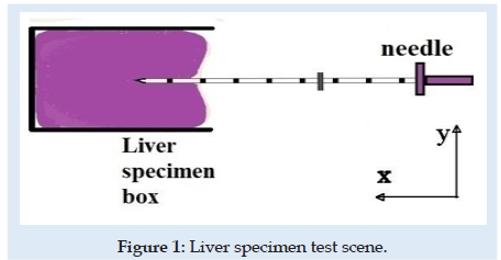
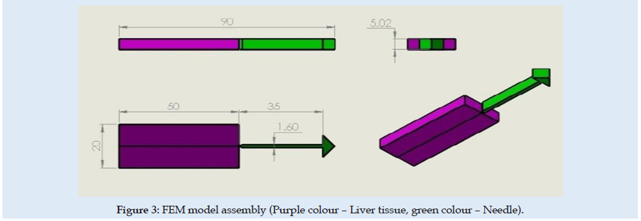
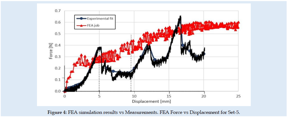
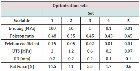
The experimental testing scene is schematically presented in (Figure 1). The specimen material was a pig liver with a cuboid shape that fits into a specimen box with dimensions presented in (Figures 2 & 3). Experimental results are according to [4]. Results obtained for material characteristics based on many authors reveal differences between the mechanical properties of liver tissues. For example, the young modulus for liver tissues according to other authors’ research can vary between 0.01 ÷ 20 MPa [18,19]. There are some differences between measurements obtained in experimental tests on human liver and liver obtained from the pig specimens. Some mechanical properties of tissues are considered variable for the optimization process used in the numerical simulation using FEA and trying to match the experimental curve presented in (Figure 4). These variables are defined in (Table 1). Initially defined in set-1 and during optimization until the last step in set-5. Each set is a group of predefined fixed values for the young modulus of the tissue with many other optimization steps under for the rest variables more sensitive [20-27].
Figure 2: Brachytherapy needles: (left – Needle types for brachytherapy; right – Needle’s end-tip and brachytherapy seeds).

Simulation Test
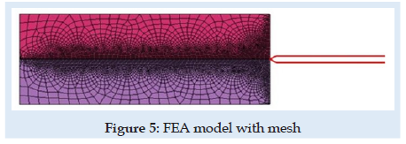
A novel virtual needle insertion simulation test is presented using a non-linear FEA with large displacement, damage to the material, friction, and contact conditions. The FEA is a method that uses decomposition of the continuous domains into a set of discrete sub-domains to solve problems that involve complex elasticity from structural analysis problems based on an energy principle and using some structural behavior idealization reduced at each small element area. Such reduction of a complex domain at a small volume provides a great advantage to employing local deformation or stress-state comprehensively. Finally, the entire domain behavior is recomputed by a field of each output parameter like a sum of all results at specific locations named nodes spread over the domain. FEM considered for simulation is a 2D with planestrain behavior. Units used for simulation were [mm, Newton, MPa]. The model is considered symmetrical. The needle part was considered rigid because in an ideal model with isotropic material and a symmetrical model specimen the lateral deformation in the needle is near “zero” unless post-buckling behavior exists. Future research can involve other biocompatible materials like Stainless Steel. A large-strain elastoplastic material model was used for the tissue part. Penetration forces were measured only in the x-direction (Figure 1). The speed of the needle in the insertion phase is 1mm/sec described by imposed displacements. The needle diameter is 1.6 mm. FEM dimensions are presented in Figure 3. Is used 6059 FEA elements with plain-strain behavior. Plate thickness was considered 5.02 mm, a complete length circle with 1.6 mm diameter. Mesh size varies depending on interest between 0.001÷2mm. For mesh quality number of trials was kept under 2.5% and zero elements in middle areas for elements with aspect >2 for tissue material. According to [28-30] the human liver density is around 1.0. In calculation is used 1.05 [g/mL] (Figure 5).
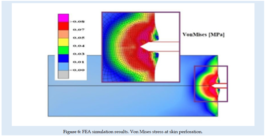
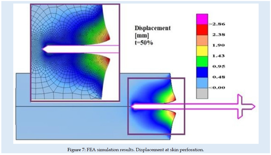
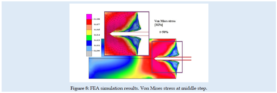
Figures 6 & 7 present stress and displacement fields at skin penetration, around the value of 2.5 mm displacement of the needle. Figures 8 & 9 present stress and displacement fields at 50% from the entire simulation time (12.5 mm x-displacement at needle). Figures 10 & 11 are presented stress and displacement fields at end of the simulation time (25 mm displacement at the needle in the X direction). FEA simulation results and curve presented in (Figure 4), show a variation around a median value not only because of FEA idealization and mechanical dynamics but also because of sequential behavior of material based on the stress-strain-damage curve of tissue material idealization presented in (Figure 12). Advantages of using the FEA simulation test for medical purposes:
a) Results parameters could be viewed in the field over the domain, at any specific location, or in a specific direction in the case of vector or tensors.
b) Results distribution reveals some concentration tendencies in specific zones, in most cases impossible to observe by other methods.
c) Probabilistic failure of materials based on definitions is shown very clear as location and as safety distribution.
d) Possibility to extend the study for more variable domains, boundary and test conditions, structure behavior at new loads and other materials, improve the initial design, optimization based on various variables, and general conditions most of them external to the initial project.
e) Medical domain even is one of the most important domains of our daily life, still offers fewer details about procedures. More study is needed for many aspects related to humans and not only human body parts behavior. But we, humans, are only at the first steps.
Figure 12: Needle end-tip geometry- arrow angle. In green colour - current used. In red colour – Possible for futures study.

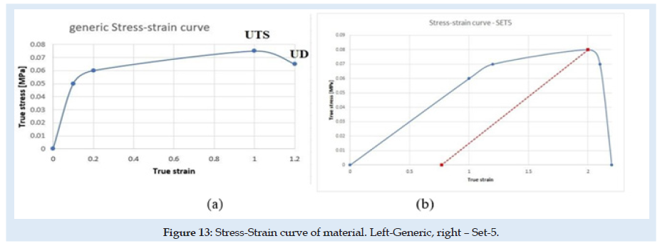
In green colour - current used. In red colour – Possible for futures study For this FEA simulation was used non-linear solver from CalculiX software. Mesh discretization was made using Gmsh software. Solving nonlinear problems involves a combination of incremental and iterative procedures using the Newton method to solve the nonlinear equations. When material damage initiates, the stress-strain relationship no longer accurately represents the material’s behavior. Continuing to use the stress-strain relation will introduce a strong strain concentration depending on the energy dissipated highly influenced by mesh size. Then probably mesh needs to be refined. But here is used a different approach is required following the strain-softening branch of the stress-strain response curve based on experimental observations that stress decreases dramatically. Next to the UTS point is used Hillerborg’s [31,32] fracture theory based on energy for the use of a stress-displacement response after the damage is initiated. Minimum incremental steps limits used were 1e-15 from simulation step length.
Liver tissue material is considered here material with isotropic hardening behavior and is presented in (Figure 13). generic in (a) and only for SET-5 in (b). Is defined as generic because the curve doesn’t remain fixed at each sub-set, depends on the Ultimate Tensile Stress (UTS), the Ultimate Damage (UD) parameters presented in (Table 1) and the elastic limit of the material as 90 percent from UTS. Other authors show that a hyperplastic material behavior for soft tissues could have better results in compression and even in tension [33-37]. But FEA simulation is difficult to implement using hyperplastic and damage in the same simulation because of structural instability. A new material behavior investigation is needed. The fracture of material grains appears in most situations in the tension state of the material. Many material behaviors today are under re-evaluation and development of new theory for complex and more complete stress- strain-damage-state behavior of materials. Experimental results show that the skin penetration is evaluated at a 5 mm displacement of the needle. This was reconsidered in FEA simulation only at 2.5 mm displacement at the needle. The differences between experimental and FEA results we will study in the future. The liver material and skin are more complex and with more irregularities.
Reaction force at the needle is a nonlinear function that depends on many characteristics of tissue, the geometry of the needle, insertion speed, etc. This formula is affected more in the case of a full simulation test when we are interested in the force near the final point of the process and can be expressed as:
Force(needle) = f (E,UTS,UD, fric,v) eq. 1
where ν is the Poisson coefficient for tissue material and in the previous formula the influence of the geometry of the needle is not considered.
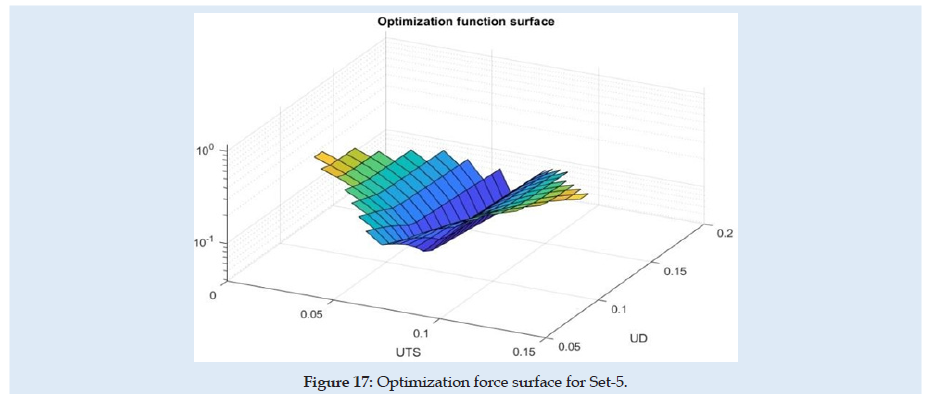
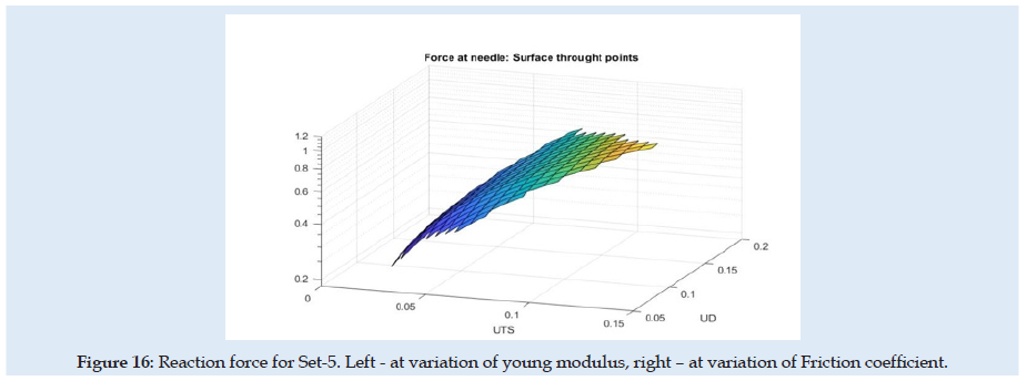
(Figure 14) can see the reaction force at the needle during the complete cycle of analysis when only the optimization parameter young modulus of material (E) or friction coefficient is changed. Similar results are presented in (Figures 15-17), but for changes in UTS or UD optimization parameters. sensitivity analysis is considered based on objective function variation during variation of optimization variables with one parameter variable and all other fixed. The objective function for optimization evaluation is the difference between reaction force in the X-direction at the needle and the force obtained in experimental results (0.6 N at the fit curve) at the optimum point check location. The point of the optimum check is the needle displacement of 16.5 mm (Figure 4). Optimization variables for each sub-set are Poisson ration, friction coefficient, UTS, and UD parameters. Accepted variation of each optimization variable is considered in domain [0 ÷200%] from his initial with fixed 5 values equal spaced. Optimization objective function has the form:
min(|(Force (needle)-Fref|)
Where Fref is considered 0.6 [N] for optimum point check location.
Figure 14: Reaction force for Set-5. Left - at variation of young modulus, right – at variation of Friction coefficient.

Figure 15: Reaction force for Set-5. Left - at variation of young modulus, right – at variation of Friction coefficient.

Figure 16:Reaction force for Set-5. Left - at variation of young modulus, right – at variation of Friction coefficient.
Because of the nonlinearity of the reaction force at the needle, the optimization method needed many steps and time for numerical simulation and post-processing of the results. In (Table 1) are presented only the best results from each sub-set considered. for each next simulation set for the evaluation, the initial values were considered optimum results from the previous set. A summary of the results from sensitivity evaluation at set-5 is presented in (Table 2). For each optimization parameter alone was made FEA until the final insertion displacement. the reaction at the needle is most sensitive to UTS and UD parameters.
Conclusion
a) Simulation tests show a good correlation with the experiment. A small number of specimens and simulations considered cannot allow a complete study of the liver stiffness in all real conditions during injection with drugs. Future study is recommended.
b) Non-linear specimen simulation test until 25 mm final displacement shows that mathematical model is not relevant sensible for Young modulus and the Poisson coefficient for the liver specimen. Sensitivity analysis reveals that the most important tissue properties are stress at damage initiation and deformation at full damage.
c) This study can be improved by considering more complex biological parts in tissues (vein, material density variation, principal directions, etc.).
d) New study needs to be developed for more experimental testing conditions with measurements of the forces not only in the vertical direction. Also, simulation and experimental tests with different types of needle-tip, speed, and penetration angle conditions are necessary.
e) Future study can be developed with current FE model for optimum needle design, insertion speed, inclination angle of insert direction, maximum depth, retractive forces, evaluation of ultrasonic guided needles during entire procedures, interactive virtual simulations in conjunction with roboticarms movement, effect of deviation from initial insertion path, evaluation of haptic devices in case of soft tissue with obstacles (tumors), etc.
Acknowledgement
a) This work was supported by a grant of the Romanian ministry of Research and Innovation, CCCDI–UEFISCDI, project number PN-III-P1-1.2-PCCDI-2017- 0221/59PCCDI/2018 (IMPROVE), within PNCDI III.
Lupine Publishers, Surgery & Case Studies: Open Access Journal, ISSN: 2643-6760.
References
- Van-Gerwen DJ, Dankelman J, Van-Den-Dobbelsteen JJ (2012) Needle–tissue interaction forces–A survey of experimental data. Med Eng Phys 34(6): 665–680.
- Dragne C (2020) Optimization of trajectories in laparoscopic surgery – 3d virtual
- Ericson C (2004) Real-Time Collision Detection, The Morgan Kaufmann Series in Interactive 3-D Technology, CRC
- Barnet T, Andrew C, Yuan-Shin L, Moore, Jason Z (2018) Needle geometry effect on vibration, tissue cutting, J Engineering 232(5): 827–837.
- Taylor RH, Joskowicz L (2003) Computer-integrated surgery and medical robotics, In: Kutz M (ed.) Standard handbook of biomedical engineering & New York, McGrawHill.
- Rembold U, Burghart CR (2001) Surgical robotics: An introduction. J Intell Robot Syst 30: 1-28.
- Perissat J (1999) Laparoscopic surgery: a pioneer’s point of World J Surg 23: 863-868.
- Ballntyne GH (2002) Robotic surgery, telerobotic surgery, telepresence, and telementoring, Endoscop. Other Intervention Technic 16: 1389-1402.
- Frazel P, Misof K, Zizak I, Rapp G, Amenitsch H, et al. (1998) Fibrillar structure and mechanical properties of collagen, J Struct Biol 122(1): 119-122.
- Holzapeel GA (2000) Nonlinear solid mechanics, Chichester,
- Dimaio SP, Salcudean SE (2003) Needle insertion modeling and simulation, IEEE Robot and Autom 19(5): 864-875.
- Drange C (2019) Robotics Design -Inverse and Directional Kinematics, SISOM Conference.
- Öpik R, Hunt A, Ristolainen A, Aubin PM, Kruusmaa M (2012) Development of High-Fidelity Liver and Kidney Phantom Organs for Use with Robotic Surgical Systems, The Fourth IEEE RAS/EMBS International Conference on Biomedical Robotics and Biomechatronic, Roma, Italy. 24-27.
- Gonçalves AC, Cavassana S, Chavarette FR, Outa R, Casarin JS (2020) Variation of the Penetration Effort in an Artificial Tissue by Hypodermic Needles, Journal of Healthcare
- Mihai La, Chin L, Janmey Pa, Goriely AA, et al. (2015) Comparison of hyperelastic constitutive models applicable to brain and fat tissues. J R Soc Interface p. 12.
- Sparks J, Dupaix RB (2008) Constitutive Modeling of Rate-Dependent Stress–Strain Behavior of Human Liver in Blunt Impact Loading, September 2008, Annals of Biomedical Engineering 36(11): 1883-1892.
- Davis SP, Landis BJ, Adams ZH, Allen MG, Prausnitz Mr (2004) Insertion of Microneedles into Skin: Measurement and Prediction of Insertion Force and Needle Fracture J Biomech 37: 1155-1163.
- Abolhassani N, Patel R, Moallem M (2007) Needle Insertion Into Soft Tissue: A Survey. Med Eeg Phys 29(4): 413-431.
- Griffin M, Premakumar Y, Seifalian A, Butler PE, Szarko M (2016) Biomechanical Characterization of Human Soft Tissues Using Indentation and Tensile Testing. J Vis Exp 118: 54872.
- Gere JM, Goodno BJ (2009) Mechanics of Cengage Learning.
- Serban Dan-Andrei, Liviu M, Niels M (2015) Finite Element Modelling of the Progressive Damage and Failure of Thermoplastic Polymers in Puncture Procedia Engineering 109: 97-104.
- Hsieh ZH, Fan CH, Yi-Ju H, Li ML, Kuang Yeh C (2020) Improvement of light penetration in biological tissue using an ultrasound-induced heating Sci Rep 10(1): 17406.
- Jiang L, Huang Y, Pan C, Ling J, Li J, et al. (2016) Research on Insertion Process of Medical International Conference on Materials Engineering, Manufacturing Technology and Control (ICMEMTC).
- Miller K (2005) Method of testing very soft biological tissues in compression. J Biomech 38(1): 153-158.
- Mihai LA, Goriely A (2017) How to characterize a nonlinear elastic material? A review on nonlinear constitutive parameters in isotropic finite elasticity. Proc R Soc A 473(2207): 20170607.
- Kataoka H, Washio T, Kiyoyuki C, Kazuyuki M, Christina S, et al. (2002) Measurement of the tip and friction force acting on a needle during penetration. Med Image Comput Comput Assist Interv pp: 216-223.
- Boctor EM, Choti MA, Burdette EC, Webster RJ (2008) Three- dimensional ultrasound-guided robotic needle placement: An experimental evaluation. Int J Med Robot 4(2): 180-191.
- Dimaio SP, Salcudean SE (2005) Interactive simulation of needle insertion models. IEEE Transactions on Biomedical Engineering 52(7): 1167-1179.
- Fu YB, Chui CK (2014) Modelling and simulation of porcine liver tissue indentation using finite element method and uniaxial stress–strain Journal of Biomechanics 47(10): 2430-2435.
- Overmoyer BA, Mclaren CE, Brittenham GM (1987) Uniformity of liver density and nonheme (storage) iron Arch Pathol Lab Med 111(6): 549-554.
- Hillerborg A, Modéer M, Petersson PE (1976) Analysis of crack formation and crack growth in concrete by means of fracture mechanics and finite elements. Cement and Concrete Research 6(6): 773-781.
- Hillerborg A (1985) The theoretical basis of a method to determine the fracture energy GF of concrete. Materials and Structures 18: 291-296.
- Wu JZ, Cutlip RG, Andrew ME, Dong RG (2007) Simultaneous determination of the nonlinear-elastic properties of skin and subcutaneous tissue in unconfined compression tests. Skin Research and Technology 13(1): 34-42.
- Morriss L, Adam Wittek A, Miller K (2008) Compression testing of very soft biological tissues using semi- confined configuration-A word of caution. J Biomech 41(1): 235-238.
- Zhao J, Cao C, Li G, Chao L, Ding H, et al. (2020) Study on the Similarity of Biomechanical Behavior between Gelatin and Porcine BioMed Res Int 2020: 7021636.
- Jacobus C, Jennifer LG (1995) Method and system for simulating medical procedures including virtual reality and control method and system for use therein. US Patent: 5: 769,640.
- Terzano M, Dini D, Baena FR, Spagnoli A, Oldfeld M (2020) An adaptive finite element model for steerable Biomech Model Mechanobiol 19(5): 1809-1825.

Top Editors
-

Mark E Smith
Bio chemistry
University of Texas Medical Branch, USA -

Lawrence A Presley
Department of Criminal Justice
Liberty University, USA -

Thomas W Miller
Department of Psychiatry
University of Kentucky, USA -

Gjumrakch Aliev
Department of Medicine
Gally International Biomedical Research & Consulting LLC, USA -

Christopher Bryant
Department of Urbanisation and Agricultural
Montreal university, USA -

Robert William Frare
Oral & Maxillofacial Pathology
New York University, USA -

Rudolph Modesto Navari
Gastroenterology and Hepatology
University of Alabama, UK -

Andrew Hague
Department of Medicine
Universities of Bradford, UK -

George Gregory Buttigieg
Maltese College of Obstetrics and Gynaecology, Europe -

Chen-Hsiung Yeh
Oncology
Circulogene Theranostics, England -
.png)
Emilio Bucio-Carrillo
Radiation Chemistry
National University of Mexico, USA -
.jpg)
Casey J Grenier
Analytical Chemistry
Wentworth Institute of Technology, USA -
Hany Atalah
Minimally Invasive Surgery
Mercer University school of Medicine, USA -

Abu-Hussein Muhamad
Pediatric Dentistry
University of Athens , Greece

The annual scholar awards from Lupine Publishers honor a selected number Read More...


