


Lupine Publishers Group
Lupine Publishers
ISSN: 2643-6736
Research Article(ISSN: 2643-6736) 
Numerical Solution of the Nernst-Planck Equation for Ionic Polymer Metal Composite Fixed- Fixed Beam Volume 3 - Issue 2
Received:August 14, 2021 Published: August 30, 2021
Corresponding author:Hamid Soleimanimehr, Assistant Professor of Mechanical Engineering, Department of mechanical engineering, Science and Research Branch, Islamic Azad University, Tehran, Iran
DOI: 10.32474/ARME.2021.03.000158
Abstract
A numerical Solution of the Nernst-Planck equation for ionic polymer metal composites fixed-fixed beam is required for measuring deflection and stress of IPMCs. These results are extremely important for analyzing this material under variable voltage and preparing it for using in complicated accessories and using it in introducing the material behavior in electromechanical analysis. As a new smart material, ionic polymer metal composites, or in short IPMCs, are typically fabricated by coating noble metals such as gold, platinum, and palladium on each other sides of membrane-based on perfluorinated materials such as Nafion and Flemion. These composites can bend significantly by applying a low amount of voltage. In this research after creating a 2-dimensional model, the equations are applied to the finite element method, then the boundary conditions are applied. The result significantly illustrates the non-linearity attitude of ionic polymer metal composites. after applying 3.3 V, considering this method, the analysis and diagrams show that the maximum stress is 2.21×10¹² (N/m2) and the maximum deflection is 0.5 mm.
Keywords: Nernst-Planck; Perfluorinated; Nafion; Flemion; Biomedical
Introduction
In recent years, polymers have played a remarkable role in biomimetic, biomedical, and robotic applications [1]. Polymers have the ability to be converted into electro-active polymers or in the other words EAPs, with different chemical techniques [2]. Electro- active polymers have drawn great attention recently because of their ability to convert electrical energy directly to mechanical work. EAPs are usually classified into two main categories based on their working mechanism: electronic and ionic [3]. Ionic EAPs such as Ionic polymer-metal composites can deform by applying a very low voltage leading to a bending movement [4]. Considering, ionic polymer metal composites are used vastly for like drug delivery, under-water microrobot, energy harvesting, soft actuators, and artificial muscles [5]. The most common polymers are consisted of perfluorinated alkene containing short sidechains terminated with an ionic group such as SO_3^-and, there are three main polymeric ion exchanges membrane consisting of Nafion, Flemion, and Aciplex [6]. The membrane is composed with a noble metal such as silver, gold, platinum, and palladium in some chemical process. In our research, we used Nafion117 membrane, Nafion is used as a conductor for proton exchange in fuel cells and water filtration and allow cations to move, coated with gold [7]. In previous research of other researchers Fick’s law and electromechanical equations were used but in this paper Nernst–Planck equation are the Enovation with can lead to more precise results [8]. One of the most important behaviors of ionic polymer metal composites is displacement because of applying a small amount of voltage. The voltage can be included in range of 1-5 v. Investigation on the range of displacement has a noticeable role in the production and development of Ionic polymer composites for use in many medical and industrial applications [9,10]. In this research, the propose is analyzing fixed-ended beam made of ionic polymer metal composite based on Nafion and Platinum with aid of finite element method and Nernst- Planck equation in COMSOL Multiphysics; the maximum stress and displacement of the beam and displacement by using this method is discussed. Due to the better understanding of the finite element method, we review the ruling equations and relations of the IPMC. Therefore, the results of this study help to comprehend the ability and resistance of the IPMC.
Structure and Equations
IPMC is complicated the smart material that can be manufactured in diverse methods [8]. For instance, it can be manufactured with putting three different layers of polymer and electrode together [9] Or combining Nafion or in the other words the liquid polymer with salt of a metal such as Platinum, gold, and etc. which will make our polymer conductive [11]. In this research the first method is used to model the IPMC and preparing it for analyzing it [12]. In this section, the ruling equations and relations applying a voltage are mentioned. Generally, IPMCs are made of a membrane put between two electrode layers (Figure 1). The electromechanical theory of ionic polymer metal composites is based on the converting of electrical energy to mechanical energy, and mechanoelectrical theory is based on the reverse of electromechanical. Both of the phenomena are induced the ionic current in the polymer calculating with Nernst–Planck equation (1) [13-14].
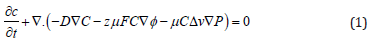
Figure 1: Laterality of Vocal Cord Paralysis.

Where “μ” is the mobility of cations, “F” is the Faraday constant, “z” is the charge number, “Δv” is the molar volume that quantifies the cation hydrophilicity, “P” is the solvent pressure, and “ф” is the electric potential in the polymer, where “C” is the cation concentration, “D” is the diffusion constant. The electromechanical and mechanoelectrical transduction models of IPMC are shown in Figure 1 [15]. For calculating applying force to fixed-fixed beam made of Ionic Polymer metal composites, it needs to use Newton’s Second Law. Generalized Newton’s Second Law is used to described the force in equation (2)[15].
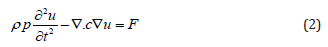
where “c” is the Navier constant and “ρp” is the density of the material and the second term is the static Navier’s equation (Figure 2). Gauss’s law is used to determine the elements and boundaries of a fixed-fixed beam made of IPMC calculating ionic current. In Figure 3, electrode domains “Ψa”, “Ψb”, a polymer domain “Ω” and, a contour “∂г” in the IPMC are shown. Considering “∂г”, the generalized Gauss’s law integral can be calculated by equation (3) [16].
Figure 2: Transduction models of IPMC.

Figure 3: Using Gauss’s law to determine elements.

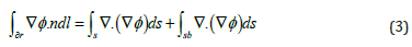
where “n” is a unit normal vector on “∂ᴦ”.
.The total current is calculated by equation (4), and the vertical directional width of the IPMC is shown in Figure 4 [17-18].
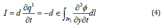
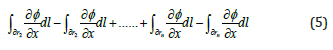
Many numbers of contour are considered, where n→∞, and the length of the counter areas with “dᴦi”, “dᴦai”, and “dᴦbi” for the vertical, top, and bottom area are shown in Figure 4. Considering that the line integrals on the inner boundaries cancel each other out, the LHS contains term, and it is shown in equation (5) [19-20].
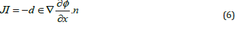
Considering the previous equations, the normal ionic current density is calculated by equation (6) [21-22].
Finite Element Method
For analyzing the mentioned composite, a computer aided engineering software is used; dimension of the modeled composite is like (Table 1). All of the previous mentioned equations are applied to the FEM method. In this analysis 118763 triangular mesh grids are made; each of them is about 0.5mm to 3.3mm; increasing this number is useless due to the precise data resulted by this amount. Next step is applying the boundary condition. First of all, since the required model is fixed-fixed beam, which means in the boundary condition of both ends there is no displacement in neither of directions. Then the voltage is applied; the upper layer is 3.3V and the lower one is the ground terminal. The last step of this analysis is applying the material properties; Nafion and Platinum are applied to the main core and to thin layers respectively; these properties are shown in Tables 2 & 3.
Result and Discussion
After computing and solving the Nernst-Planck equation, it is understood that the maximum deflection of the modeled beam is 0.5 mm (Figure 5). The maximum Von Mises stress occurs in the electrodes near the fixed ends, and it is about 2.21×10¹² (N/m2) (Figure 6). It is obvious that in the middle of our beam we have the maximum deflection in the other words due to the normal equations and other types of beams as we have fixed ended being in our research the maximum displacement will occur at the midpoint; since follows Timoshenko beam theory it can be understood that the maximum This stress will take care indie electrodes especially the fixed parts. The strain of our model is extremely low which is perfect for using them in manufacturing micropumps; The vibration that causes by this item after applying AC voltage Can result an amazing flowrate. As it was expected the displacement entire of IPMC, they’ve been like Figure 7 which will decrease at the ends and increase while approaching the midpoint. This is an usual phenomenon occurred because the theory followed by our beam is Timoshenko.
Table 1: The specification of fixed-fixed beam.

Table 2: Nafion 117 properties [12].

Table 3: Platinum properties [12].

Figure 4: The boundaries of IPMC elements.

Figure 5: Graphical displacement of fixed ended beam.

Figure 6: The stress in the electrodes of the model.

Figure 7: Displacement graph in the IPMC beam.

Conclusion
The ionic polymer metal composite in the form of a fixed-fixed beam with the electrode of platinum and Nafion membrane has been modeled. By applying a voltage of 3.3V, the stress and deflection have been investigated by finite element method and the diagrams have been drawn, in addition, Nernst–Planck and Poisson equations have been used in the calculation of ionic current. It has been realized the fixed-fixed can tolerate 0.5mm as maximum deflection and 2.21×10¹² (N/m2) as maximum stress. The maximum stress will happen in the electrode especially the fixed parts and the maximum deflection or in the other world the formation will occur in the middle of the IPMC beam. Due to the high and low strain of this beam at 3.3V and high response to the voltage alteration this model is perfectly matches with micropumps.
References
- D Chen, Q Pei (2017) Electronic muscles and skins: a review of soft sensors and actuators. Chem Rev 117(17): 11239-11268.
- G Alici, G Spinks, N Huynh, L Sarmadi, R Minato (2007) Establishment of a biomimetic device based on tri-layer polymer actuators-propulsion fin. Bioinspir Biomim 2(2): 18-30.
- Y Bar Cohen (2007) Electroactive Polymer (EAP)Actuators as Artificial Muscles:Reality, Potential, and Challenges. SPIE Publications.
- B Bhandari, G Lee, S H Ahn (2012) A review on IPMC material as actuators and sensors: fabrications, characteristics and applications. Int J Precis Eng Manuf 14: 141–163.
- K Asaka, K Kim, K Oguro, M Shahinpoor (2016) IPMCs as EAPs: fundamentals. Electromech Active Polymers pp: 131-150.
- O Kim, S Kim, M Park (2018) Low-voltage-driven soft actuators. Chem Commun 54(39): 4895-4904.
- Y Tang, Z Xue, X Zhou, X Xie,C Y Tang (2014) Novel sulfonated polysulfone ion exchange for ionic polymer–metal composite actuators.Sensors and Actuators B: Chemical 202: 1164-1174.
- Soleimanimehr H, Nasrollah A (2021) A Numerical Investigation the Effects of the Voltage on the Displacement and Stress of Copper-based Ionic Polymer-Metal Composites. Journal of Modern Processes in Manufacturing and Production 10(1): 77-86.
- L Chang, H Chen, Z Zhu, B Li (2012) Manufacturing process and electrode properties of palladium-electroded ionic polymer-metal composite. Smart Mater Struct 21(6).
- Y Wang, Z Zicai, L Jiayu, C Longfei, C Hualing (2016) Effects of surface roughening of Nafion 117 on the mechanical and physicochemical properties of ionic polymer-metal composite (IPMC) actuators. Smart Mater Struct 25(8).
- H Qingsong, Y Min, D Haitao, G Dongjie, D Zhendong (2010) Effects of anisotropic surface texture on the performance of ionic polymer-metal composite (IPMC). SPIE Smart Structures and Materials + Nondestructive Evaluation and Health Monitoring San Diego California United States.
- A Nasrollah, H Soleimanimehr, H Khazeni (2021) Nafion-based ionic-polymer-metal composites: Displacement rate analysis by changing electrode properties. Advanced Journal of Science and Engineering 2(1): 51-58.
- B Zhang, C Hualing, W Yanjie, J Shuhai, W Yongquan, et al. (2014) Comparison of plasma treatment and sandblast preprocessing for IPMC actuator. SPIE Smart Structures and Materials + Nondestructive Evaluation and Health Monitoring San Diego California United States.
- C Pugal, P Solin, K J Kim, A Aabloo (2014) hp-FEM Electromechanical transduction model of ionic polymer–metal composites. J Comput Appl Mathem 260: 135-148.
- S Nemat Nasser, J Y Li (2000) Electromechanical response of ionic polymer-metal composites. J Appl Phys 87(7): 3321-3331.
- K Farinholt, D J Leo (2004) Modeling of electromechanical charge sensoring in ionic polymer transducers. Mechanics of Materials 36(5): 421-433.
- Z Chen, X Tan, A Will, C Ziel (2007) A dynamic model for ionic polymer metal composite sensors. Smart Mater Struct 16(4): 1477.
- D Pugal, P Solin, A Aabloo, K Kim (2013) IPMC mechanoelectrical transduction: its scalability and optimization. Smart Mater Struct 22(12).
- M Porfiri (2009) An electromechanical model for sensing and actuation of ionic polymer metal composites. Smart Mater Struct 18(1).
- M Aureli, W Lin, M Porfiri (2009) On the capacitance-boost of ionic polymer metal composites due to electroless plating: theory and experiments. J Appl Phys 105.
- B Akle, M Bennett, D Leo, K Wiles, J McGrath (2007) Direct assembly process: a novel fabrication technique for large strain ionic polymer transducers. J Mater Sci 42: 7031-7041.
- A Punning, M Kruusmaa, A Aabloo (2007) Surface resistance experiments with IPMC sensors and actuators. Sens Actuators 133(1): 200-209.


-

Mark E Smith
Bio chemistry
University of Texas Medical Branch, USA -

Lawrence A Presley
Department of Criminal Justice
Liberty University, USA -

Thomas W Miller
Department of Psychiatry
University of Kentucky, USA -

Gjumrakch Aliev
Department of Medicine
Gally International Biomedical Research & Consulting LLC, USA -

Christopher Bryant
Department of Urbanisation and Agricultural
Montreal university, USA -

Robert William Frare
Oral & Maxillofacial Pathology
New York University, USA -

Rudolph Modesto Navari
Gastroenterology and Hepatology
University of Alabama, UK -

Andrew Hague
Department of Medicine
Universities of Bradford, UK -

George Gregory Buttigieg
Maltese College of Obstetrics and Gynaecology, Europe -

Chen-Hsiung Yeh
Oncology
Circulogene Theranostics, England -
.png)
Emilio Bucio-Carrillo
Radiation Chemistry
National University of Mexico, USA -
.jpg)
Casey J Grenier
Analytical Chemistry
Wentworth Institute of Technology, USA -

Hany Atalah
Minimally Invasive Surgery
Mercer University school of Medicine, USA -

Abu-Hussein Muhamad
Pediatric Dentistry
University of Athens , Greece
