


Lupine Publishers Group
Lupine Publishers
ISSN: 2643-6736
Research article(ISSN: 2643-6736) 
Numerical Investigation of Particle Tracking to Achieve High Impact Velocity in Cold Spray Volume 2 - Issue 4
Received: July 20, 2020; Published: July 29, 2020
Corresponding author: Muhammad Sohail Malik, Ghulam Ishaq Khan Institute of Engineering Sciences and Technology, Swabi, Pakistan
DOI: 10.32474/ARME.2020.02.000145
Abstract
Cold spray is a coating technique that allows for solid state deposition of particles under atmospheric conditions of pressure and temperature. In cold spray micron size particles are impinged upon a substrate as a result of high velocity impact. The acceleration of particles to a high velocity is achieved by expanding a pressurized gas in a supersonic convergentdivergent nozzle. The performance of cold spray technique can be judged by several parameters, one of which is the deposition efficiency based on impact velocity. It is observed in this work that particles having small diameters achieve high velocities during nozzle acceleration, but they also decelerate rapidly in the flow downstream of the bow shock wave because of having low momentum. The main concern of this paper was to examine the effect of particle size on impact velocity in the cold spray process and to find an optimum range of particle diameter which could result in greater impact velocity at the given conditions. For this purpose, Zinc particles having diameters range (1-50) microns were used to simulate in a supersonic nozzle numerically.
Keywords: Cold gas dynamic spraying (CGDS); Impact velocity; Deposition Criteria; Critical velocity; Particle impact temperature; Computational fluid dynamics (CFD)
Introduction
With the progression of time there is a lot of improvement in technology and also in material science. New standards and tolerances came along with a greater demand of enhance surface qualities. For good surface properties we need to have some special type of coating techniques. Cold spray which is also called Cold Gas Dynamic Spray (CGDS) is a sibstitue method to conventional deposition techniques such as thermal spraying, wire arc spraying and plasma spraying. Cold spray is a solid-state material deposition technique, where micron-sized particles of a powder bond to a substrate as a result of high-velocity impact and the associated severe plastic deformation [1] Many drawbacks such as high-temperature oxidation, melting, crystallization, evaporation, residual stresses and gas release etc. which are happening due to traditional thermal spraying techniques are avioded by using Cold Spray technique. Acceleration of particles to high velocities is obtained via expansion of a pressurized gas through a convergent-divergent nozzle. Cold Spray technology was invented by Dr. Anatolii Papyrin and his colleagues in the mid-1980s at the Institute of Theoretical and Applied Mechanics of the Russian Academy of Sciences in Novosibirsk [2]. This research group observed that sometimes the particles coated on the target instead of eroding it when they were doing experiments on the design of high-speed “re-entry vehicles” using a supersonic wind tunnel [3]. This unintentional deposition phenomenon during wind tunnel experiments formed the basis for further study on cold spray. Anatolii Papyrin published a patent in US in 1994 and a European patent in 1995.
After almost four decades of development, cold gas dynamic spraying has become an important branch of thermal spraying. As a newly developed coating technique, this process enables the development of numerous coatings such as pure metals, alloys, composites, nanostructure materials, and even amorphous materials. Almost all the conventional coating techniques use high temperature for deposition purposes; therefore, they are not suitable for temperature sensitive materials. In the cold spray particles are injected in the nozzle at either inlet region of the nozzle or diverging part of the nozzle downstream the throat at room temperature. If the particles are injected at the nozzle inlet region, higher final velocities can be achieved as the particles are entrained in the jet stream for a long period of time. On the other hand, if the particles are injected at the diverging section of the nozzle at low pressure zone then the impact speed reduces [4].
To improve the deposition efficiency, preheating substrate has been employed. Fukumoto et al. [5]. found that particle depositability was remarkably increased with the increase of substrate temperature in cold spraying of copper. However, Legoux et al. [6] found that the deposition efficiency of zinc decreased with the decrease in substrate temperature, while that of Al increased. According to the previous results [7], increasing the gas pressure could increase the particle velocity and slightly decrease the particle temperature. Moreover, it was found that increasing the gas temperature contributed to the increase of both particle temperature and velocity. However, it was reported that the critical velocity greatly depends on particle temperature and decreases with the increase of particle temperature [8,9] moreover, the deposition efficiency also increases with the increase in throat diameter and vice versa [10]. But too much increase in throat diameter causes huge drop in pressure inside the nozzle.
In the application of cold-spray technology, we want to improve the deposition efficiency (DE), defined as the ratio of the weight of adhered particles to the total weight of sprayed particles. To date, the optimized spraying conditions that yield high DE for cold spray are mostly determined on a trial-and-error basis [11-13] which not only incurs substantial cost but also time-consuming. Li et al. [14] numerically investigated the cold spray process by investigating under-expanded and over-expanded streams. They analyzed nozzle exit conditions and suggested a conventional shock model for the calculation of cold spray powder particle impact speed. Moreover, the deposition efficiency also depends on standoff distance (the distance between exit of the nozzle and substrate). Generally, the standoff distance ranges from 10 mm to 40 mm. Yin et al. [15] studied impact process in cold spraying and reported a technique for modeling multi-particle impact process in cold spray. They conducted a comparative study in detail between Eulerian, Lagrangian and smoothed particle hydrodynamics (SPH) methods to discuss bond formation and multi-particle impacts. They studied and simulated particle deformation behavior in 2-dimension and 3-dimension using an explicit LS-DYNA program. The outcome of their simulation is that the Lagrangian metod significantly depends upon the element type for multi-particle impact and upon the meshing size.
The Eulerian method outcome was close to the experimental data and can be regarded as superior to the other ones. However, mesh-free SPH showed reasonable results in particle deformation behavior and the weight of independent SPH particle imply limited effects on the output. Karimi et al. [16] successfully developed the CFD model of the cold spray to simulate the gas flow and powder particle trajectories in a supersonic nozzle before and after the impact with the substrate. Xian-Jin et al. [17], suggested a twodimensional numerical method for cold spray process and simulated the velocity and temperature of powder particles in low-pressure cold spray process. They used implicit Fluent CFD code to simulate the supersonic gas flow for helium and nitrogen gas. RNG k-ε model was used for solving turbulence in flow. This model predicted the temperature of particle in supersonic gas flow satisfactorily and it can provide an important reference for lo pressure cold spray process within limited constraints. Samareh et al. [18], presented a 3-dimensional model of cold spray by examining the effect of substrate shape and location. They used Fluent® code to examine the effect of substrate geometry.
In that study the particle landing location on the substrate, the particle normal impact velocity and the effect of stand-off distances were observed. According to their findings, the optimum location for the substrate from the nozzle exit particularly in the case when cold spray nozzle is operated at low pressure is 10 mm. Moreover, this study reveals that particle dispersion is less when cylindrical substrate is used instead of flat rectangular substrate. Observing all the above discussion, cold spray a lot of research has been caried out in the this field. However, there are some deficiencies at the computational side of cold spray. There is almost no work that has been carried out at the simulation side of particle injection. Hence, the aim of this study was to present the computational simulation of particles that what is the depostion effeciency of cold spray at the specific boundary conditions.
Methodology
Methodology can be divided into further parts.
Geometry
A two-dimensional model of a convergent-divergent nozzle was modeled in ANSYS® ICEM® having dimensions shown in Table 1 and the nozzle geometry is shown in Figure 1.
Table 1: NozzleDimensions.

Mesh Independence Test
Mesh has been constructed in ICEM® module of ANSYS® 16.1. In order to analyze the flow in the nozzle, a hexahedral mesh was developed (Figure 2) using blocking method. The edges of blocks were then associated with the vertices of nozzle geometry. The convergence criteria are set to be less than for all the variables. To check the reliability of the solution, a mesh independence test is performed for the case of 16 micrometer diameter particle with grid numbers ranging from 45786 to 70986. The total number of nodes calculated were 119360 and the total number of elements were 58855. This was selected because of having smaller relative error. The relative error for any parameter (M) between the finest grid and the other grids is calculated by the following equation:
Where M stands for any parameter.
Figure 1: Nozzle geometry.

Figure 2: Mesh of the model.

Table 2: Mesh independence test.

Computational Setup
Simulation was done in two steps:
a) Single phase simulation by using air as a driving gas.
b) Multiphase flow by injecting zinc particles using Rosin
rammler methodology.
Single phase: Air was chosen as the driving gas in this study. The ideal gas law was used to calculate the density in order to take the compressibility effects into consideration. In order to capture the turbulent flow features accurately, the standard K-ε turbulence model available in FLUENT was utilized for modeling the turbulent flow in the simulation. The choice was made by following the work of Li et al. [14]. The standard wall function was chosen for the near-wall flow treatment. K-ε turbulence model has a benefit of robustness and flexibility to maintain optimum computation time as compared to other turbulence models such as normal velocity relaxation model (v2-f), large eddy simulation (LES), shear stress transport (SST), or normal velocity relaxation model. Zuckerman and Lior etc [10], presented a comprehensive comparative study about the numerical modeling techniques used in supersonic jet impingement process. Normal velocity relaxation turbulence model (v2-f) has been declared as the most reliable method for solving turbulence in fluid flow but at very high computational cost. This is in contrast to 15%-60% acceptable error for k-ε model with the most cost effectiveness in terms of computational time and hardware requirements. ANSYS® ICEM® release 16.1, an implicit CFD software was chosen to develop the 2D multicomponent model for cold spray process.
Boundary conditions: The working and carrier gas (air) was considered as an ideal and compressible one. A coupled implicit solver was used to obtain the steady state flow field. Flows were modeled through the double precision method (2ddp). Secondorder scheme was applied in all calculation cases. Turbulence was modeled using the k-ε standard model. This type of model was successfully applied for simulation of the gas flow under cold spray conditions. The nozzle walls were assumed as isothermal ones. The substrate (Aluminum) was placed at a 20 mm distance from the nozzle exit (stand-off distance). Stagnation pressure at the nozzle inlet was set at 1.2Mpa. The environmental pressure was equal to the atmospheric one (101325Pa). Simulation was made with working gas stagnation temperature: T0= 300 K.
Particle injection: The main concern of this paper was to simulate the particle injection in order to study the effect of particle size on impact velocity of zinc in cold spray technology. The focus of this study was the deposition of zinc but Copper and gold were also used as the spraying particle material. The acceleration of particles was computed using discrete phase modeling (DPM). The model requires that the discrete phase must be present at sufficiently low volume fractions. In this case, all the spray particles are spherical in shape and hence the spherical drag law is used to compute the drag coefficient. Particle–particle interactions and the effect of particles on the gas phase can be neglected. The model used was discrete phase modeling with transient flow analysis. The discrete phase volume fraction should preferably be less than 10% and the volume fraction of particle used in the present study was about 5%. The pressure-based analysis was preferred for this work. Calculation of particle parameters was performed through one-way coupling. In all the cases, the particles were considered as spherical ones.
Results and Discussion
This section is further divided into four sections.
a) In the first sections the results of single phase (air) are shown
in order to study the behaviour of gas before injecting particle
into it.
b) In the second section the contours of multiphase consisting of
air and zinc are shown in order to study the behaviour of gas
after injecting particles into it.
c) In the third section the impact velocity was compared with
critical velocity showing the range of deposition.
d) In the fourth section the velocity of gas and particles having
different diameters was plotted against the path length to
show which particle has the better performance at the impact.
Gas Flow Results
The contours of velocity, temperature, pressure, and mach number was plotted Figure 3 against the path length, which are showing the behaviour of gas at different points of the nozzle,geometry.
Multiphase Results
The contours for multiphase flow velocity, temperature, pressure, and mach number was plotted Figure 4 against the path length, which are showing the behaviour of multiphase flow at different points of the nozzle geometry.
Validation
To check the reliability of the present simulation, this work is validated with the work of Yin et al. [15]. It can observed from Figure 5 that the present simulation is in a good agreement with the work of Yin et al. [15], thus indicating that the present model can be used to predict the properties of cold spray setup used in this study.
Figure 3: Contours of velocity, temperature, pressure, and mach number for single phase.

Figure 4: Contours of velocity, temperature, pressure, and mach number for Multiphase

Figure 5: Validation of particle impact velocity with Yin et al. [15].

Deposition Criterions
The basic principle for the deposition of particle is that the particle impact velocity must be greater than the critical velocity otherwise the particle will not be deposited, and they will reflect back after impact at the substrate. There is no mathematical formula for deposition criteria. The only method to find the critical velocity is to use the empirical formulas defined by different researchers. In this paper the following three deposition criterions were used to plot the critical velocities against the particle diameter. Also, the impact velocity was plotted against the particle diameter
Criteria 1:
Here cp is the particle specific heat in J/Kg.K,Tm is the particle melting temperature in 0C, ρp is the particle density in Kg/m3, and Tpi is the particle impact temperature in 0C.
Criteria 2:
Here cp is the particle specific heat in J/Kg.K,Tm is the particle
melting temperature in K, ρp is the particle density is in Kg/m3, σTS is
the particle tensile strength
in Pa, and Tpi is the particle impact temperaturein K.
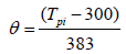
Where a and b are constants having values a=4, b=0.25, is temperature dependent flow stress and can be find by
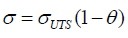
where is normalized temperature and can be find by equation
Below are the three deposition criterions plotted with the help of excel by putting the impact temperature and velocity results getting from the present simulation. It was observed that there is a neglibible change in the results of all the deposition criterions which also verify the results of our simulation. In the below graph critical 1 shows the result of formula 1, critical 2 shows the result of formula 2, and Vcr 3 shows the results of formula 3.
Optimum Range of Particle Size for Deposition
From the above graph Figure 6 it is clearly shown that particles having diameters less than 15 microns and greater than 40 microns have an impact velocity less than the critical velocity, which means that they will not be deposited on the substrate rather they will be reflected after striking. From the above graph Figure 6 it is also very clear that the best range of particle diameters observed for the deposition of zinc was from 25 to 35 microns.
Effect of Bow Shock Wave on Gas and Particle
Firstly the gas was simulated alone and its velocity was plotted against the path length. Then particles of five different diameters ranging from 1 to 60 microns were injected and their behaviour was studied from inlet of the nozzle to the impact point at substrate. The velocity of both the particle and carrier gas was observed to be increasing up to the exit of De Laval nozzle because of the expansion of gas. The further increased in velocities up to 150mm is due to the under-expansion phenomenon. The sudden drop in velocity Figure 7 from 150mm to 160mm is due to the bow shock effect. This drop in velocity greatly depends on momentum. As the momentum of gas is very low, so its impact velocity reaches almost zero near the substrate because it cannot move against the bow shock wave. As the diameter of particle was increased from 1 micron to 40 microns, an increase in the impact velocity was observed because the momentum of particle increases, due to which there was a less effect of bow shock to resist the particle. As the particle diameter was increased above 40 microns, a decrease in impact velocity occurred, because the carrier gas now unable to carry such a large particle.
Figure 6: Deposition criterions.

Figure 7.

Conclusion
Particle deposition and consolidation by cold spray has been modeled through the application of ANSYS® FLUENT®. Particle velocities and temperatures were predicted at the nozzle exit, downstream of the bow shock and at the substrate surface.These conditions can be used to predict the deposition efficiency. It has often been thought that the smallest particles attain highest velocities in the cold spray process, thus achieving good deposition efficiency. While it is true that small particles exit the nozzle at high velocity, but their velocity at the impact can be significantly lower. The efforts of this study showed that the low gas velocity following the bow shock wave decreases particle velocities, especially for the smallest particles. It was shown that impact velocity increases as the particle diameter inceases until a diameter of about 35 μm is reached. Impact velocity then decreases as the particle diameter is further increased. This effect can reduce the deposition efficiency, because the deposition efficiency is directlty related with the impact velocity. These observations have been qualitatively known in the cold spray community but quantitative guidelines were not well established. The simulation effort presented here for zinc gives the ability to anticipate coating results based upon the spray parameters and material characteristics, thus eliminating trial and error attempts at creating acceptable coatings.
References
- Assadi H (2016)Cold spraying-a materials perspective. Acta Materialia 116: 382-407.
- Papyrin A (2006) Cold spray technology Elsevier.
- Pawlowski L (2008) The science and engineering of thermal spray coatings.
- Ryabinin A (2015) Calculation of the Particle Velocity in Cold Spray in the One-Dimensional Non-Isentropic Approach. ARPN Journal of Engineering and Applied Sciences 10(6): 2435-2439.
- Fukumoto M, Wada k, Tanae k, Yamada M, Yamaguchi E, et al (2007)ThermalSpray Technol 5(6) : 643.
- Legoux JG, Irissou E,Moreau c,Therm J (2007)Thermal Spray Technol 5(6): 619.
- Li WY, Liao H, Wang HT, Li CJ, Zhang G, et al (2006) Appl Surf Sci 2: 708.
- Grujicic M,Zhao CL,DeRosset WS, Helfritch D (2004) Mater Des 8: 681.
- Fukanuma H, Ohno N,Sun B, Huang RZ (2006) Surf Coat Technol 5: 1935.
- Meng F (2016) Cold-spray bonding mechanisms and deposition efficiency prediction for particle/substrate with distinct deformability. Materials & Design109: 503-510.
- Alkhimov A, Kosarev VF, Papyrin A (1990) A method of cold gas-dynamic spraying. Doklady Akademii Nauk SSSR 315(5): 1062-1065.
- Dykhuizen R, Smith M (1998)Gasdynamicprinciplesofcoldspray.JThermSpray Technol7(2): 205-212.
- GilmoreDL,Dykhuizen RC,Neiser RA,Smith MF, Roemer TJ (1999) Particle velocityanddepositionefficiencyinthecoldsprayprocess.JTherm SprayTechnol8: 576-582.
- Li S, Muddle B, Jahedi M, Soria J (2012) A numerical investigation of the cold sprayprocessusing under-expanded and over-expanded jets. JTherm Spray Technol 21: 108-120.
- Yin S, Wang X, Xu B,Li W (2010) Examination on the calculation method for modeling the multi-particle impact process in cold spraying. J Therm Spray Technol 19: 1032-1041.
- Karimi M, Fartaj A, Rankin G, Vanderzwet D, Birtch W (2006) Numerical simulation of the cold gas dynamic spray process. J Therm Spray Technol 15: 518-523.
- Ning X, WangQS,MaZ, KimH (2010)Numericalstudyofin-flightparticle parametersinlow-pressurecoldsprayprocess. JThermSprayTechnol 19: 1211-1217.
- Samareh B, Stier O,Luthen V, Dolatabadi A (2009)Assessment of CFD modeling viaflow visualization in cold spray process. J Therm Spray Technol18: 934-943.
- Grigoriev S, Okunkova A,Sova A,Bertrand P, Smuro I (2015) Cold spraying: From process fundamentals towards advanced applications.Surface & Coatings Technology 268: 77-84.


-

Mark E Smith
Bio chemistry
University of Texas Medical Branch, USA -

Lawrence A Presley
Department of Criminal Justice
Liberty University, USA -

Thomas W Miller
Department of Psychiatry
University of Kentucky, USA -

Gjumrakch Aliev
Department of Medicine
Gally International Biomedical Research & Consulting LLC, USA -

Christopher Bryant
Department of Urbanisation and Agricultural
Montreal university, USA -

Robert William Frare
Oral & Maxillofacial Pathology
New York University, USA -

Rudolph Modesto Navari
Gastroenterology and Hepatology
University of Alabama, UK -

Andrew Hague
Department of Medicine
Universities of Bradford, UK -

George Gregory Buttigieg
Maltese College of Obstetrics and Gynaecology, Europe -

Chen-Hsiung Yeh
Oncology
Circulogene Theranostics, England -
.png)
Emilio Bucio-Carrillo
Radiation Chemistry
National University of Mexico, USA -
.jpg)
Casey J Grenier
Analytical Chemistry
Wentworth Institute of Technology, USA -

Hany Atalah
Minimally Invasive Surgery
Mercer University school of Medicine, USA -

Abu-Hussein Muhamad
Pediatric Dentistry
University of Athens , Greece
