


Lupine Publishers Group
Lupine Publishers
ISSN: 2643-6736
Research Article(ISSN: 2643-6736) 
Novel Design, Vibration Analysis and Mechanical System Hardware of a Serial Three-Link Flexible Robot Interfaced with A Mini-Gripper Volume 3 - Issue 3
Received:November 17, 2021 Published: November 30, 2021
Corresponding author: Pratik Chothe, Robotics Division, SVR Infotech, Pune, India
DOI: 10.32474/ARME.2021.03.000161
Abstract
Flexible Robotic System (FRS) is a real-time dynamic multi-body system that has various challenging issues related to real-time control of its inherent self-propagating type of vibration. The present research reports a novel, distinctive and unique design of a representative multi-degrees-of-freedom FRS, augmented with worm-gear based revolute joints. The paper addresses novel design semantics as well as vibration analysis of a three degrees-of-freedom flexible robotic arm, fitted with a mini-gripper at its distal link. The design of the ‘test’ and prototype flexible robotic arms was carried out along with the stress, deflection & modal analysis of the links and joints a-priori. Besides development of the laboratory-based test hardware as well as beta version (prototype) of the FRS, the paper focuses on new insight towards modelling of the inherent vibration and brings out its effect on the associated dynamics of the FRS.
Keywords: Flexible Robotic System; Revolute Joint; Dynamics; Vibration; Hardware; Rheology Gripper
Introduction
Study on Flexible Robotic System (FRS) is one of the
distinguishing domains of modern-age robotics research that deals
with various challenging issues like tackling slenderness of the
mechanical sub-assemblies and harnessing real-time vibration,
inherent in the system. This vibration is completely built-in type
and thus it is design invariant. By nature, vibration in FRS is selfpropagating
and does not follow rule-based analytical modelling
in real-time applications. This inherent vibration is totally selfgenerating,
structure independent and can be classified mainly in
two ways, namely: Modal frequency and Eigen value. A sizeable
amount of basic research, case studies and design attempts with
hardware implementations took place in the past to overcome this
vibration in FRS. But most of those attempts were unsuccessful
because of its incoherent and self-propagating nature. Due to its
slenderness and light-weight endeavor, FRS is capable of working in
compact zones and, thus it is stepping significantly in the emerging
domains of medical diagnosis and other para-medical / healthcare
applications. Although FRS is getting tuned for various real-time
applications, yet the major design bottleneck remains with the
effective control of inherent random vibration.
The prototype FRS-ensemble (beta version), developed out of
the present research, is aimed at use in hospitals to help the bedridden
patients as & when the need arises. This Patient Assistant
Robot (PAR) is designed to pick and place objects like pills, tablets,
bottles, cotton, spoon etc. and transfer the items to the patient,
based on the urge from the patient. The prototype FRS system has
maximum horizontal reach of 1500 mm, spanned in three unequal
links in totality. The prototype PAR ensemble consists of three
links, three revolute joints, two flexible shafts, a mini gripper, a recirculating
ball screw, a tripod and various electrical sub-systems
like motors, motion controllers & drivers. The extreme two links of
the FRS are driven by worm gear based revolute joints and powered
by flexible shafts. These two flexible shafts are coupled with
respective motor shafts, fitted in the FRS-links. The prototype FRS
has been interfaced with a novel indigenously designed lightweight
mini gripper. This miniaturized gripper of the prototype FRS can
pick and place object(s) with almost zero probability of error, as
experimented out in this work. The payload will be gripped by the
gripper at the extreme end of the links and the other end will be
attached to the motor using couplings.
In-depth Finite Element Analysis (FEA) was conducted in
order to arrive at the finalized design of the revolute joint as it
must be strong enough to sustain the torsional load. Although
the FRS with revolute joints will ensure better maneuverability
and reachability in the workspace, on the flip side, the design will
escalate deflection & in-situ vibration / trembling of the FRS-links.
The vibration problem gets complex and highly coupled because of
the assemblage of multiple links & joints in the ensemble system.
To add to this difficulty, vibration analysis of FRS-links becomes
even more critical due of the augmentation of flexible shafts in the
system. This additional source of vibration occurs while motorpower
gets transmitted to the links through rotating flexible shafts.
Randomized vibration gets inducted into the assembly because of
the rotation of the flexible shafts, which will call for program-level
control of the robotic system, along with the mini-gripper in realtime.
Besides, the prototype FRS will undergo substantial twist of
the joints as major component of the external load-fraction will
be concentrated on the revolute joints. Besides design analysis of
the joints, in-depth FEA was carried out for each and every part of
the prototype FRS in order to maintain its strength in general. In a
similar way, analysis and grasp evaluation of the FRS-gripper was
performed to grip a payload of 800gram (max). Simultaneously,
FEA was performed so as to ascertain minimum deformation of the
distal link of the FRS in order to prevent sagging of the mini-gripper
and deflection thereof. Since complete elimination of the deflection
& vibration of the FRS was not possible, due attention was paid
to keep the ensemble deflection of the FRS-links & gripper under
control through servomotor-loop.
Besides prototyping, systematic studies were carried out in this
work in exploring the pathways for reducing the in-built vibration
of the FRS, considering various combinations of non-metallic
materials for the links & joint assemblies. The final selection of
the materials for the links & revolute joints was made based on
the results of the analysis, under the aegis of minimum vibration /
deflection and optimal load carrying capacity.
Real-time control issues of FRS have gained research attention
over the last few decades, which deal with novel techniques of
control of system dynamics in real-time [1], inclusive of harnessing
self-propagating vibration in the system [2]. While perturbation
method was tried for fine-tuning FRS-controller [3], direct real-time
feedback from strain gauges was experimented too [4]. It is true that
a robust dynamic model becomes very effective in understanding
the behavior of FRS in real-time and the same becomes crucial for
a multi-link FRS [5,6]. Dynamics of multi-body FRS has been one of
the major focal themes of research so far as stability analysis of the
flexible system is concerned, be it large displacement-based theory
[7] or beam-axis deformation-based proposition [8]. Detailed
dynamic analysis of planar flexible mechanisms was reported by
Song & Haug [9].
Feliu et al, attempted the control issue of a three degreesof-
freedom FRS using the methodology of inverse dynamics in
contrast to strain gauge-based control [10-11]. It is true that a
robust dynamic model becomes very effective in understanding
the behavior of FRS in real-time [12] and the same becomes crucial
for a multi-link FRS, such as novel dynamic model of FRS based on
spring and rigid bodies [13]. The fuzzy learning-based approach
for control of FRS [14]. Specific metrics related to reduction of
system vibration of a robotic gadget were attributed by Singer &
Seering [15]. Various techniques for vibration attenuation & control
in FRS have been reported hitherto, such as sliding mode theory
[16], adaptive resonant control [17], online frequency & damping
estimation [18] & integral resonant control [19]. Tracking control
of flexible systems using disturbance-based estimation has gained
significance in applications [20]. New paradigms on guidance and
control of flexible robotic systems have been experimented out,
using Linear-Quadratic-Gaussian design methods [21] and closedform
solutions for feedback control [22]. However, modeling of the
multi-link FRS using compliant sub-assemblies, such as springdashpot-
damper and flexible shafts, remains an open research
domain till date. Indigenous design, system modeling, FEA and
worthy hardware development of two ‘test-beds’, respectively for
3-degrees-of-freedom planar & articulated-type FRS, fitted with
mini-grippers, have been reported by our group in [23-26]. In both
of these ‘test-beds’, we explored the subtleness of the design of the
FRS-links so as to imbibe enough compliance for better reachability
of the manipulator inside the robotic workspaces and also for the
ultimate objective of grasping of payload by the end-of-arm tooling
of the FRS, namely, the miniaturized jaw-type gripper. A detailed
analysis on the origin, source apportionment, real-time evaluation,
and control of inherent vibration in multi-degrees-of-freedom FRS
can be referred for assessment as well as estimation of the systemlevel
vibration of FRS [27]. The maiden design and firmware of a
Patient Assistance Flexible Robot was delineated by Roy [28].
We have inferred through our earlier work that although
FRS-hardware with revolute joints makes it simpler and more
reliable from reachability & manoeuvrability point of view, yet
the major bottleneck remains with its inherent vibration. Hence,
studies have been carried out in a cumulative way in finding
out different pathways for reducing the in-built vibration of the
prototype flexible robot, as part of the present work. Based on the
experience learnt in our earlier research, we have pin-pointed two
fundamental aspects for the design of the prototype PAR, namely:
a] distribution of the total planar stretch of the FRS to decide over
the link-lengths and b] type of cross-section of the links. It is very
important to synchronize lengthwise division of the planar reach of
the FRS using ergonomics & aesthetics for effective utilization of its
work-zone in plane. Unlike the link-lengths, selection of the crosssection
of the FRS-links is crucial for calculating the volume of the
links and finally, mass of the FRS-links. Thus, the slenderness of the
prototype FRS was ensured through our indigenous design of the
links, having hollow cross-section.
The paper has been organized in six sections. An overview of the
mechanical design of the prototype multi-degrees of freedom FRS is
presented in the next section. Section 3 describes the subtle details
of the joint sub-assembly & mini gripper of PAR. Details on the finite
element model of the FRS and vibration signature simulation have been discussed in section 4. Chronological report on the paradigms
of hardware manifestations of the designed FRS (from ‘test-beds’ to
final beta version prototype) is addressed in section 5, along with a
glimpse over the developed controller of the FRS. Finally, section 6
concludes the paper.
Mechanical Design of The Developed Prototype of Three-Link Serial-Chain Flexible Robotic System
Design Conceptualization
As an important prelude to the development of the prototype
PAR, we have conceptualized the detailed firmware for building a
generic three-link three degrees-of-freedom planar serial-chain
FRS. The crux of this generalized design is the ensemble planar
stretch of the FRS, which has been instrumental in deciding the
number of links of the FRS and the link-lengths. At this stage of
conceptualization, we were more engrossed with the lengthwise
branching of the FRS so that the overall planar reach could be
synchronized effectively to have the near-perfect utilization of
the workspace. Since the planar reach of our prototype FRS was
horizontal, we were free to divide the same in three sections so
as to satisfy the overall layout from ergonomics as well. The other
wing of our design conceptualization was related to the choice of
cross-section of the FRS-links. We opted for tapered cross-section
of the FRS-links so as to have overall reduction of the tare-weight
of the prototype. (Figure 1) schematically illustrates the planar
disposition layout of such a serial-chain three-link FRS, fitted with
flexible shafts and mini-gripper. The artist’s view of Figure 1 is not
in scale.
We would like to highlight two important parameters of the
concept-design as shown in Figure 1. The first one is ‘Horizontal
Span’ of the planar FRS that takes care of the actual disposition
of the developed FRS prototype, post-fabrication, and assembly.
As illustrated in Figure 1, horizontal span is calculated starting
from the left-most corner of the base sub-assembly of the FRS
and ending at the right-most corner of the micro-gripper. The
estimation of the horizontal span is very vital in the design process
as it gives a preliminary idea about the extended workspace of
the FRS. The ideation of horizontal span is equally important
for the experimentation inside laboratory as well as in real-life
application environment. The second parameter of importance in
design conceptualization is the ‘Ensemble Link-length’, which is
the arithmetic summation of the lengths of the three links of the
FRS. The ideation on ensemble link-length is crucial from the point
of view of manufacturing as the individual links will be fabricated
based on the exact lengths of those, as per the design. The individual
link-lengths, represented as ‘L1’, ‘L2’ & ‘L3’ in Figure 1 are derived
from the overall conceptualization of this ensemble link-length.
One crucial aspect of the design conceptualization of a planar
FRS is selection of the type of cross-section of the links, namely,
solid vis-à-vis hollow. Besides external shape, the internal layout
of the links does matter significantly so far as generation of in-situ
vibration is concerned. Obviously, mass compliance is a big issue in
designing planar FRS and naturally, the desired choice for the crosssection
of links will be hollow type. To add to it, tapered crosssection
of the links, as selected in our prototype, will be definitely
useful towards reduction of mass of the FRS and better slenderness
ratio. This reduction of mass will be instrumental in harnessing
the in-situ vibration. However, manufacturability of slender links
with tapered hollow cross-section is indeed crucial and it requires
special fixtures for the machine tool.
At design conceptualization phase we did not make attempt to
develop the drive system layout of the FRS, except accommodating
the base sub-assembly. We have considered the motor housing to
be placed inside the base sub-assembly that will drive the first joint
of the FRS. However, we have not gone for detailing of the drive
systems for the second & third joints. This detailing was carried out
in steps, aided by indigenous design of the revolute joints and also
easy pathway of transferring rotary motions to the second & third
joints via a novel flexible mechanism. The details of these designmetrics
are reported in the next sub-section.
Finalized Design for the Prototype
As part of design finalization of the prototype FRS, we
concentrated the effort on two salient aspects, namely: a] placement
of the drive-motors of the joints and b] method of transmission
of power to the joints. In-line with the planar disposition of the
FRS as shown in Figure 1, all three drive motors of this three-link
FRS have been designed for placement at the base of the FRS, in
order to imbibe more stability of the slender robotic system as
well as to reduce the coupled weight at the links and thereby, insitu
vibration of the system. Although it is possible to augment
miniature servomotors at the link-joint interface, the same will lead
to unwarranted drooping of the links from time to time during joint
actuation. This perpetual drooping will be coupled with additional
trembling of the system even if the servomotors are compact and
lightweight. Hence direct-drive technology for link actuation is
not the ideal design to be implemented for planar FRS. It is to be
noted here that this in-built vibration of an FRS occurs in the form
of trembling of the links and at times, in form of slight torsion too.
Nevertheless, increased stability at FRS-base by virtue of placement
of the motors always help in resisting the in-situ vibration of the
prototype FRS.
The method of transmission of power from the respective
drive-motors at the base to the corresponding joint-axes is a crucial
design issue for planar FRS. As the drive-motors are placed at
FRS-base, respective joints will be actuated through flexible shafts
in our design. The indigenously developed flexible shafts will be
integrated in the system as mechanical connection between the
motor-output-shaft & the joint-shaft. Figure 2 shows the layout of
the prototype FRS as per the finalized design metrics. As per the
finalized design scheme, the prototype FRS is having three tapered
links and three revolute type joints with no joint at the ‘wrist’, i.e.,
between the distal link and the micro-gripper. The prototype FRS
consists of three links having two worm gear-based revolute joints
in-between for the link actuation.
As shown in Figure 2, servomotors for the joint actuations are
fitted at the base of the FRS assembly, which reduces the excessive
load on the links. While the motor-tuple {M1, M2 & M3} is located
at the base of the FRS, the motor, M4 is interfaced at the wrist that
is responsible for the operation of the micro-gripper. The drive for
joint 1 is direct, i.e., coupled straight away with the main assembly
via M1. The drives for joint 2 & joint 3 are through the flexible
shafts, via worm gear based revolute joints, which are coupled
with the motor shafts. Thus, destination-actuation at the jointlink
interface gets realized by the flexible shafts, which are driven
by the same servomotors at the FRS-base assembly. One of the
novelties of our FRS is related to the design of the flexible shafts
in a compact cost-effective manner. Both of the flexible shafts have
been designed from scratch and developed with indigenous effort.
The driver end (left hand side) of the flexible shaft is the shaft of
the respective motor (M2 or M3) and the transmission is carried
over to the driven end of the shaft (right hand side) and thereafter
to the joint. The crucial-most aspect of the mechanical design of the
prototype three-link FRS is to have effective drive and actuating
system through an optimal mechanism for the revolute joint(s).
With this viewpoint in mind, we have conceptualized the basic
schematic layout of the prototype three-link FRS, as illustrated in
Figure 1 & 2. The final prototype has been made in modular fashion,
so that links can be detached easily as and when required in order
to smoothen the dynamics in real-time.
Figure 1: Artist’s View of the Planar Layout of a Serial-Chain Three-Link Flexible Robotic System.

Figure 2: Design Schematic of the Prototype 3-Link Flexible Shaft-driven FRS.

Issues on Design for Manufacturing of the Prototype
The sole motto of the design for manufacturing of the prototype FRS was to develop a lightweight and compact FRS, with multifunctional sub-assemblies. The developed hardware of the prototype FRS was realized as an experimental platform for PAR with this objective in mind. The prototype FRS consists of three circular cross-sectioned links of lengths 800 mm, 400 mm & 200 mm respectively. The material for construction of the links is Carbon Fiber Reinforced Plastic (CFRP), which is light weight as well as having high mechanical strength. The design for manufacturing of the prototype FRS turned out to be more light weight since we have restricted the internal diameter of the hollow link(s) to 10 mm. only. As a matter of fact, the design for manufacturing of links is quite challenging because the links are slender and not to exceed 10 mm. in outside diameter. Thus, the links are designed in such a way so as to reduce the effective weight without sacrificing torsional endurance. These facets have been achieved by making the links hollow and also tapered at one end. By virtue of this layout, the overall tare weight of the link assembly gets reduced with an improvement in its bending resistance. It may be noted that the tare weight of the FRS-link is low because CFRP has very low density as compared to metals, which reduces the torque requirements for the drive-motors as well. Nonetheless, the design for manufacturing of FRS-links is more challenging because of the limitations of the self-weight, which promotes to vibration at an enhanced fashion. In contrast to the paradigm of low tare weight of the FRS-links, each link has been designed in a way to make it torsional rigid too. The augmentation of the drive sub-assembly at the base of the prototype FRS is a crucial tool of design for manufacturing that helps reducing the dynamic load on the links in case ‘direct-drive’ design would have selected.
Sub-Assembly-Level Computer-Aided Design of the Prototype
The design for manufacturing of the prototype PAR was realized
through various crucial sub-assembly-level designs, namely:
a) revolute joint
b) mini gripper
c) base & tripod mechanism and
d) counter-balancing mechanism.
We will detail out the salient technical features of these four
sub-assemblies through Computer-Aided Design (CAD).
Design of Revolute Joints
The indigenously designed revolute joints were used in the
prototype FRS for enabling the rotation of the links in a smooth
& non-interfering mode. These joints were conceptualized as the
smooth non-interfering type ‘pin’ joint rotations without consuming
much spatial volume. This simple ‘pin’-type connection between
two mating pairs was the crux of the design of our revolute joints.
Figure 3 presents detailed schematic of a typical revolute joint that
was fabricated and used in the final mechanical hardware of PAR,
along with its basic CAD model.
As illustrated in Figure 3a, the revolute joints were fabricated as
simple bearing-supported pin joints, with an extended flange at the
bottom. These are essentially single degree-of-freedom kinematic
pair, consisting of two parts, viz. joint housing & adapter plate.
The adapter plate has a pin that extends through the joint housing
and then gets coupled to a flexible shaft. Notwithstanding its own
assembly, fixation of these revolute joints into small & slender links
of the prototype FRS is equally challenging (refer Figure 3b for
details).
Figure 3a: Indigenously Developed Revolute Joint Assembly of Prototype FRS: Schematic.
Index: A: Pin; B: Micro-Bearing (Upper Rung); C: Micro-Bearing (Lower Rung); D: Joint Housing; E: Adapter Plate; F: Fixing
Screws; G: Extension Plate. below the figure 3a.

Figure 3b: Indigenously Developed Revolute Joint Assembly of Prototype FRS: b] Basic CAD Model.
Index: 1: Lower Housing; 2: Upper Housing; 3: Access for Bearings; 4: Joint Shaft.

As shown in Figure 3a, the adapter plate sits firmly on the joint
housing. Then after, joint housing and adapter plate get fixed to the
link, which in turn provides the rotational motion to the link. The
joint housing encloses two sets of micro-bearings that supports the
pin over & above the adapter plate and makes free rotation of the pin,
so formed, a reality. It is interesting to note the synergy between the
conceptual schematic and basic CAD of the FRS-joint, as illustrated
in Figure 3b. The compartmentalization of the housing of the joint
has been the prime objective for basic CAD, as it is required for the
actual assembly of the links of the FRS with the joint housing as
well as the joint shaft. We have extended the basic CAD of Figure
3b to an elaborated design with the functional components of the
joint sub-assembly. Figure 4 illustrates the labelled schematic of the
revolute joint assembly of the serial-chain FRS, highlighting salient
dimensions of the constituent members.
As illustrated in Figure 4, the main element of the joint assembly
in the centrally located pin, having diameter ‘d’. The pin is supported
by a pair of miniaturized ball bearings (diameter: Dbr), disposed
of symmetrically with respect to the pin, one above another. The
intermediate space between the bearings, Hj is dimensionally
crucial, as actuating links will be positioned in this space. The top
casing of the pin is disposed of along both sides of the pin as a single
unit. The important design dimensions of top casing are width (Lt)
and heights on either side (Ht & Hts). In contrast to top casing, the
bottom one is fabricated as a single unit, encapsulating the central
pin. The crucial design dimensions of the bottom casing are width
(Lb) and heights on either side (Hb & Hbs). Real-time actuation of this
very revolute joint is surely a novelty of the flexible robotic system
developed.
Figure 4: Exploded Schematic of the Revolute Joint Assembly of the Prototype FRS.

Design of Mini-Gripper
The mini gripper of the prototype FRS has been designed within an external envelope of 50 mm x 40 mm x 15 mm. This lightweight mini gripper consists of sets of links attached with the jaws, which are made up of nylon having higher strength to weight ratio. The drive is designed with a compact small-sized motor while actuation is accomplished through a pair of sectors (spur) gear. The sectorspur gears are made up of aluminum (Al 6028). The gripper-jaws are parallel and being actuated through tiny links, forming a closedbar micro-mechanism. Figure 5a illustrates the basic CAD model of the mini gripper, while its topology optimized version is shown in Figure 5b. Various design alterations with respect to shape & size may be observed in the CAD model of Figure 5b, especially for components ‘B’, ‘C’, ‘D’, “E’ and ‘F’. It may be noted that the driver link (‘D’) is modeled as an integrated structure with ‘C’ (sector gears) during topology optimization phase.
Figure 5a: CAD Model of the Mini-Gripper of the Prototype FRS: Basic Model.

Figure 5b: CAD Model of the Mini-Gripper of the Prototype FRS: Topology Optimized Model.
Index: A: D.C. Motor connection; B: Base Plate; C: Sector Gears; D: Driver Link; E: Connecting Link; F: Jaw Actuating Link; G:
Jaw-Link Pin; H: Main-Link Pin; I: Inter-Link Pin; J: Jaws.

Design of Base and Tripod Mechanism
Besides joint actuation & drive transmission, the other crucial
design paradigm of the prototype FRS lies with the base of the
system. The base serves dual purpose, viz.
a) Encapsulation of hardware-gadgets
b) Transmission of linear motion to the FRS in the vertical
axis (using a recirculating ball screw mechanism). The base encloses
all motors, electrical circuits, motor drivers, motion controller (National Instruments®-make ‘NI my RIO’) & d.c. power supply
unit. The d.c. servomotors, responsible for the joint actuations, are
mounted on the top of the base.
On the other hand, the backbone of the developed FRS is
the tripod sub-assembly, comprising a customized recirculating
ball screw-nut mechanism, which sustains the tare weight of the
ensemble system and allows jerk-free up and down motion. The
base has a hole in the middle, which allows this ball screw to
pass through. The ball nut is fixed to the base itself. The whole
base assembly is mounted on the tripod stand. The tripod stand
has been designed as a foldable unit with provision for height
adjustment. The driving motor for the recirculating ball screw is
mounted on the tripod itself. Figure 6 shows the CAD model of the
base assembly and the tripod mechanism of the fabricated FRS.
As evident from Figure 6, the backbone of the design of the base
assembly is the disposition of the ball screw & nut mechanism,
aided by the guide rods, for effective control of the vertical motion
in run-time condition. It may be noted that the ball screw-driven
height adjustment of the tripod mechanism of the base is a bare
essential pre-requisite from application standpoint. Several design
iterations were made to optimize the design of the base assembly,
in order to synchronize with the stability of the prototype FRS in
operation with its full dynamics. The importance of this ball screw
mechanism is envisaged in easy maneuverability of the entire FRS as
per the requirement of the application. The ball screw mechanism
with three guide rods is fitted on the base stand as shown in Figure
6a. The vertical moving system of the multi-link FRS-assembly
rests on top of the ball screw with the thrust bearing in between,
as shown in Figure 6b.
Figure 6a: CAD Model of Tripod Mechanism.

Figure 6b: CAD Model of Base Assembly of the Prototype FRS.
Index: A: Ball Screw; B: Ball Nut; C: Tripod Stand; D: Height Adjusting Holes; E: Housing of the Base; F: Guide Rods.

Figure 7 illustrates the details of the internal mechanism of the base assembly, by expounding various functional components. It may be noted that the ball screw is coupled to a gear, indexed as ‘Screw gear (Driven)’ in Figure 7, which is driven by the gear connected to the stepper motor. Three guide shafts of 16mm diameter are connected to the moving system atop the base assembly. The fixed plate at the bottom, indexed as ‘Fixed Base’ in Figure 7, consists of a ball nut and three linear bearings. This fixed base is connected to the tripod stand (refer Figure 6b). The crucial-most member of the base assembly of the prototype FRS is the ‘Turn Table Mechanism’ (refer the transparent box-section of Figure 7), which the motion-transference junction of the device. The mechanical sub-system of this turn table mechanism involves several components with tight manufacturing tolerance and precise fit. Figure 8 illustrates the exploded assembly-view of the turn table mechanism of the prototype FRS along with labelled part-indexed manufacturing drawing (general assembly).
Figure 7: CAD Model of the Internal Mechanism of the Base Assembly of the Prototype FRS in expanded View.

The base plate (part # 1) is designed with steel sheet of thickness 2 mm that consists of suitable provisions for mounting the 3D-printed frame (‘assembly block’) at the middle of the mechanism (part # 3) and also holes for mounting the d.c. servomotor (part # 17: model: JX Servo PDI-HV5932MG; type: high voltage digital servo; rated torque: 300N), as shown in Figure 8. It may be observed that the motor is mounted on the base plate with spacer (part # 2), which is fastened by the bolts (part # 18). The pre-optimized 3D-printed mid-frame consists of two ball bearings [part # 4: dimensions: 30mm (O.D); 10mm (I.D) & 9 mm (width)] and two thrust bearings [part # 11: dimensions: 42 mm (O.D.); 25mm (I.D.) &11mm (width)]. The upper cover plate (part # 20) is connected to the base plate using the spacer (part # 21), which is fastened by the bolts (part # 13). The moving turn plate (part # 5) is connected to a flange coupling (part # 7) that rests on the upper thrust bearing. Two shaft mounts (part # 10) for holding the links of the prototype FR having outer diameter 10mm are mounted on the turn plate. A central shaft (part # 6) with threads on one end and key-slot throughout passes through the flange coupling, thrust bearings and ball bearings. The driven gear (part # 12: (PCD: 50 mm; module: 1.25; teeth: 40; teeth-width: 12 mm) is coupled with the shaft at its threaded end (bottom side). A locknut (part # 9: size: M10) is used to tighten the shaft to reduce play. The driving gear (part # 22) is used to rotate the turntable aided by a servo-horn (part # 16), powered by the motor.
Figure 8a: CAD Model of the Turn Table Mechanism of the Prototype FRS: Exploded Assembly.

Figure 8b: CAD Model of the Turn Table Mechanism of the Prototype FRS: General Assembly (manufacturing).

Design of Counter-balancing Mechanism
In order to combat the large overhung of the prototype FRS, we have designed a novel counter-balancing mechanism so as to limit excessive drooping of the FRS-links in run-time condition. The design is basically centered on a metallic wire, fitted with three props between the FRS-base and approximate endpoint of FRS-first link. The design simulation was carried out by fixing the metallic wire at the FRS-base at one end with variations in the locations of the end-prop. However, the crux of the design in centered on the height of the central prop of the mechanism. Figure 9 illustrates the overall disposition of the indigenously developed counterbalancing mechanism of the prototype FRS through CAD. As illustrated in Figure 9, one of the crucial components of the counterbalancing mechanism is the central prop. The ensemble tension in the metallic wires on both sides of the prop is dependent on the rigidity of the prop as well as its height. In fact, supporting base, ‘D’ has also important role in ensuring the rigidity of the central prop. Several design iterations were accomplished to ascertain the most optimal location of placing the end-prop, ‘E’ so as to provide maximum tension in ‘A’.
Figure 9: CAD Model of the Counter Balancing Mechanism of the Prototype FRS.

The dropping of FRS-1st. Link will be arrested substantially by the effect of the novel counter-balancing mechanism. It may be noted that the supporting base, ‘D’, is actually the ‘top cover plate’ of the base assembly that houses the servomotors for the joints via the flexible shafts. Figure 10 illustrates the CAD view of the top cover casing / prop-supporting base of the prototype FRS, atop the turn table mechanism. The physical interfacing of the link with the servomotor, aided by the coupler & servo-horn is instrumental in proper positioning of the prop-supporting base in order to ensure effectiveness of the counter-balancing mechanism in creating tension in the wire. Two servomotors are placed inside the casing, using shaft-mounts as shown in Figure 10. We may note that the flexible shaft is coupled with the motor’s crown using the coupler, which is connected to the servo shaft using a servo horn. In fact, the top cover casing is the most vital part of the flexible shaft subassembly of the prototype FRS.
Figure 10: CAD Model of the Top Cover Casing and Prop-Supporting Base of the Prototype FRS.

Computer-Aided Design of the Ensemble Assembly of the Prototype
The piece-meal CAD models of the sub-assemblies of the
prototype FRS were instrumental in generating the CAD of the
ensemble prototype. In fact, slenderness of the links has added
difficulty in the overall integration of the link-subassemblies. Figure
11 illustrates the ensemble CAD model of the prototype FRS, with its
sub-assemblies indexed. The expanded view of the said CAD model,
inclusive of base mechanism & counter-balancing mechanism is
presented in Figure 12. Accordingly, the 3D solid model of the entire
FRS with mini gripper fitted at its distal end has been realized and
thus Figure 12 shows the developed CAD model of the prototype
FRS in totality. The incorporation of the metallic wire, off FRS-base,
functions as well as the effective counter-balance mechanism for
the FRS as well as a tool to control predominant vibration, sourced
at the first link. The computer-aided design ensemble, explained
hitherto, has culminated into three facets subsequently, viz.
a) Finite element model of the FRS for vibration signature and
FEA
b) Algorithmic design of the control system of the FRS
c) Fabrication of the FRS with different materials (as ‘test-beds’)
We will dwell upon these facets in the next sub-sections.
Figure 11: Ensemble CAD Model of the Prototype FRS.

Figure 12: Expanded CAD Model of the Prototype FRS along with Mini-Gripper.

Design Metrics of The Joint Sub-Assembly & Mini- Gripper System of The Flexible Robotic System: ‘PAR’-Prototype
Two crucial metrics of our indigenous design of the threelink three degrees-of-freedom prototype FRS, namely, “PAR-beta version’, are joint sub-assembly and mini-gripper system. These two metrics are independent to each other and quite generic so far as design articulations are concerned. In fact, design of the ensemble revolute joint sub-assembly plays the most crucial role in overall system assembly vis-à-vis real-time activation of the prototype FRS. An outline of the design modulation of both of these two metrics have been delineated in section 2, which will help us to go for detailed design synthesis, as reported below.
Design Synthesis of Joint Sub-assembly
The sub-assembly of the revolute joint(s) of the prototype ‘PAR’
comprises of two functional elements, viz.: a] transmission system of
the joint, i.e., flexible shaft & end-couplings and b] activation system
of the joint, i.e., joint-shaft, bearings & housing. The drive motion
required to rotate the links of the prototype ‘PAR’ is transferred
through flexible shafts from the motors. We have zeroed on the
integration of custom-made flexible shafts in our prototype so as
to transmit maximum drive-motion to the joints. We have made
successful customization of commercially available flexible shaft
through an innovative mechanization of spring-actuated slender
power drive cord of two-wheelers. Our custom-made flexible shaft
is a unique mechanical sub-system that transmits motion between
two different non-co-axial mechanical members successfully
with minimal loss. Functionally, our custom-made flexible shaft is
similar to a solid drive; but it can be routed under, over and around
‘obstacles’, i.e., links & joints of the prototype ‘PAR’.
This indigenously developed flexible shaft is extremely rugged
and permits continuous operation at high-speed ranges of all the
three joint-motors. It also dampens system-generated vibrations
and in fact, prevents transmission of any sort of vibration from the
motor to the links. The end-couplings of the customized flexible
shaft enable us to couple those to suitable power transmitting shaft.
As part of the ensemble mechanical hardware of the prototype ‘PAR,
the motor power will be transmitted to the respective revolute joint
via flexible shaft, via two end-couplings. These two end-couplings
are interfaced respectively at the motor-end & the joint-end. Thus,
in our hardware, one end of the flexible shaft is connected to the
motor shaft and the other is connected to the pin of the revolute
joint. By virtue of this design, the pin of the revolute joint gets
enabled to transmit this motion to the respective link. Due to the
transmission of rotary motion in a continuous fashion, this pin will
be subjected to torsion & torsional vibration thereof.
Various feasible CAD model views of our custom-made flexible
shaft is shown in Figure 13a (I, II & III) along with critical design
features in Figure 13b. As evident from the schematic layout of
the prototype FRS in Figure 2, maximum bending posture of the
flexible shaft will be as shown in CAD model ‘I’ of Figure 13a that
occurs when the same is connected to the first revolute joint. Here,
the nearest clamping position of the flexible shaft will depend on
its minimum bending radius. Likewise, when the second flexible
shaft gets connected to revolute joint #2, the bending takes place
somewhat in the posture shown in CAD model ‘II’. Routing for the
flexible shaft 2 needs to be done through revolute joint #1. As this
revolute joint has a range of +180⁰ to -180⁰, this range would then
be dependent on the minimum bending radius of the flexible shaft 2
as shown in CAD model ‘II’ of Figure 13a. Likewise, various possible
bending postures of these flexible shafts are shown in CAD model
‘III’ of Figure 13a. The major design estimation of the customized
flexible shaft is its length, i.e., ‘L’ as shown in Figure 13b. However,
the overall length must be determined by closely approximating all
bends and offsets and it should be measured along the centerline
of the shaft. In other words, in case of the prototype ‘PAR’, ‘L’ was selected by considering enough clearance apart from the normal
distance of separation between Joint1 & Joint2. The bend radius
(R) is an important dimension of our flexible shaft mechanism,
besides other two dimensions; namely, ‘X’ & ‘Y’ (refer Figure 13b
for details). While ‘X’ is to be selected based on the total span of
transfer of drive from joint to link of the FRS, ‘Y’ will be instrumental
in combating torsion of the flexible shaft & FRS-link subsequently.
Although integration of a flexible shaft overcomes the need of
perfectly aligning the motor shaft and the actuating mechanism, yet
it has a major constraint of minimum bending radius, below which
the system fails.
Figure 13a: Representative View of the Custom-made Flexible Shaft: Critical Design Features.

Figure 13b: Representative View of the Custom-made Flexible Shaft: [b] Critical Design Features.

The novelty of the activation system of the joint of the developed FRS-prototype pertains to the design & fabrication of the worm gear-based revolute joint. This revolute joint primarily consists of a worm shaft and a worm gear, besides couplers & fasteners. Motion is transferred from the servomotor to the wormshaft by means of flexible shaft. Figure 14 illustrates the detailed CAD model of the indigenously developed compact revolute joint for the prototype ‘PAR’-beta version (exterior view & internal mechanism). It is important to note the staggered disposition of the constituent links, viz. link 1 & link 2 in this design that ensures maximum transmission of rotational motion through the revolute joint. As evident from the layout of Figure 14b, rotary motion is being transferred to the worm wheel by means of flexible shaft, which is coupled to the left end of worm wheel (worm gear). Finally, it is getting transmitted to the second link through the worm gear. As per the design, this worm gear can transmit a maximum torque up to 3Nm to the joint. It may be stated here that the worm –worm wheel-based mechanism of the revolute joint is entrusted not only for efficient power transmission but also vibration attenuation to a satisfactory extent. The design ensemble of this novel revolute joint and its 3D solid model have been extended to both the interim joints of the prototype FRS.
Figure 14a: CAD Model of Revolute Joint of the Prototype ‘PAR’-beta version: Exterior View.

Figure 14b: CAD Model of Revolute Joint of the Prototype ‘PAR’-beta version: Internal Mechanism.

The indigenous design of the revolute joint has its foundation on the contact mechanics of the worm & worm wheel pair in realtime. This contact mechanics is governed by the analysis of the tangential, axial & radial forcing on the worm -worm wheel pair at any time-instant. Following functional relationships have been established for the said contact mechanics in generic terms for an ‘n’ degrees-of-freedom serial-chain flexible robot having ‘n’ joints:


where, i: Joint of the FRS; [{P1_t}, {P1_a}, {P1_r)]: Tangential
/Axial / Radial component of force on worm at tth. time-instant;
[{P2_t}, {P2_a}, {P2_r)]: Tangential /Axial / Radial component of
force on worm wheel at tth. time-instant; N: Natural number-space;
k & (k+1): Any two consecutive revolute joints of the FRS.
The tangential components of contact force between the worm
& worm wheel pair bear functional relationship with two design
variables and one operational parameter. While the design variables,
namely pressure angle & helix angle of the worm & worm wheel
play significant role in defining the nature of force transmission, the
other functional parameter of the pair, viz, coefficient of dynamic
friction between the worm & worm wheel surface manoeuvre
the tangential force in real-time. We may note the functional
relationship between these two tangential components of contact
force, as detailed below:
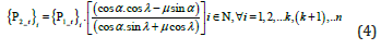
where, α : Pressure angle; λ : Helix angle and μ: Coefficient of dynamic friction. Other symbols of eqn. 4 have identical nomenclature as defined earlier. The design of the worm wheel (gear) has been made with PCD of 5mm, pressure angle of 20° & helix angle of 3.18° . The efficiency of this novel revolute joint can be evaluated via following analytical expression (as a ratio of output power to input power):

were, i ξ : Efficiency of the ith. Revolute joint; D1: Diameter of the worm; D2: Diameter of the worm wheel; N1: R.P.M. of the worm shaft (as input); N2: R.P.M. of the worm wheel (as output). Equation 5 can be recast by replacing the ratio (N2 / N1) with corresponding ratio for the gear teeth meshing, i.e. (Z1 / Z2), where {Z1, Z2} tuple indicates number of starts at worm shaft & number of teeth on worm wheel respectively. An average efficiency of 35% has been obtained for the revolute joint with this novel design. The designed torque at the worm gear (3 Nm) was arrived at by adopting traditional formula of torque evaluation for rotating bodies, which, in our case, is the circular cross-section hollow link of the FRS.
Design Synthesis of Mini-Gripper
The requirement of compatible design-match between the
low tare-weight PAR: beta version and the mini-gripper was
instrumental is taking up the design challenge of fabricating a truly
miniaturized ultra-low payload two-jaw type robotic gripper for
our prototype FRS. The principal design objective of this gripper
was rooted at low-payload grasp with adequate form & force closure
paradigms. The prototype gripper hardware was manufactured
mainly to take care of various medical necessities for patient(s) at
hospitals / health care centers, as part of the potential deployment
of ‘PAR’. The method of ‘Line diagram’ has been invoked to crystalize
the primary layout of the PAR-gripper. Figure 15 depicts the said
line diagrams of the gripper, illustrating a general idea about its
actuation along with major dimensions of various constituent
members of the same.
As illustrated in Figure 15a, the drawing-board-based design
synthesis was carried out by considering ‘maximum aperture’
of the gripper-jaws prior to the grasp. It is important to note the
aperture angle, e.g., 156° that is found to be commensurate with
the linkage layout of the gripper and actuation of those under the
effect of run-time torque of the gripper-motor. Likewise, the case
for ‘medium aperture’ can be synthesized, as shown in Figure 15b.
The safe threshold value for the gripping force is also evaluated
on the basis of the design synthesis as well as geometrical layout
of the prototype gripper system. The force of griping maximum
payload of 800 gm is arrived at 29.43 N, considering coefficient of
dynamic friction between the gripper-jaw & object surface as 0.5
and acceleration as ‘1g’.
Figure 15a: Line Diagram’ for the Synthesis of Design of PAR-Gripper: Maximum Aperture.

Figure 15b: Line Diagram’ for the Synthesis of Design of PAR-Gripper: Medium Aperture.

The customized mini gripper of ‘PAR’ works in a tiny volume, approximately 26.5 cm3, with reference to its external dimensions (length: 50 mm; width: 35 mm. & breadth: 15 mm.). As an extension of the topology-optimized model of the mini-gripper (refer Figure 5b), 3D CAD views of the developed working model of the mini-gripper are presented in Figure 16, wherein the novelty of miniaturized manufacturing can be ascertained. The phenomena of grasping involve time-specific interactions with the object by the gripper assembly (mostly the jaws & the links). The gripperjaws interact with the object by exerting force on the surface of the object, which can be of two types, namely: i] Grasping (Prehension) force & ii] Holding (Retention) force. These two forcing functions have been represented schematically in Figure 16b along with various components and joint co-ordinate frames indexed.
Figure 16: 3D CAD Model of the Mini-Gripper of the Prototype ‘PAR’: [a] General Isometric View: [b] Forcing Function View. Index: A: Base Plate (with easy attachment with robot wrist / external anchor); B: Fixation for Servomotor; C: Sector Gears; D: Intermediate Linkage; E: Jaw Plate Connecting Links; F: Jaws, {π1 ,π2 ,.........π8} : Joint Co-ordinate Frames.

a) Eight joint co-ordinate reference frames have been used in the
design synthesis of PAR-gripper prototype, viz. a] at sector
gears ( π1 & π2 )
b) At gear-intermediate link juncture ( π3 & π4 )
c) At the attachment of jaw-plate connecting link & base plate (
π5 & π6 )
d) At the interface of intermediate link & jaw-plate connecting
link ( π7 & π8 )
All of these reference co-ordinate frames are crucial for the
computation of grasp pregension and grasp retension of the PARgripper.
It is important to note that besides actuation of the sector
gear pair, the dynamics of the linkage tuple (gear-driver link,
connecting link & jaw-actuating link) plays an important role in
ascertaining the design dimension of PAR-gripper that will have a
total of 20 components in the assembly. The payload capacity of this
miniature gripper (~ 800 gm) is much consistent in comparison
to its tare-weight. In fact, payload to tare-weight ratio is quite high
for the prototype mini-gripper of ‘PAR’. The prototype PAR-gripper
has various characteristic features commensurate to its tiny size
and actuation of the jaws. It is needless to state that because of its
size miniaturization, the ensemble design is prone to higher level
of vibration, both in stand-alone condition of the jaws as well as
during grasp. As illustrated in Figure 16, the design of the base plate
was customized keeping in mind the overall size minimization,
compactness and also the optimum strategy for fitment with the
robot wrist. The open-loop control algorithm and programming
syntax of PAR-gripper were customized to get an assessment of the
real-time vibration, generated due to the grasp-load.
Finite Element Model of The Prototype Flexible Robotic System for Deflection, Vibration & Rheological Analysis
We have used Finite Element Method extensively upon
completion of the design synthesis phase of the prototype FRS,
predominantly under three broad semantic verticals, namely
a) FEA-based gross deflection analysis for the selection of
optimum material for the manufacturing of the links & joints
of the prototype FRS.
b) FEA-based vibration analysis towards evaluation of natural
frequency of vibration as well as modal frequencies of the
prototype FRS.
c) FEA-based analysis of rheological parameters (e.g., bending
stress) of the prototype FRS.
All of these three facets are critical so far as the hardware
manifestation of the prototype ‘PAR’ is concerned as well as its realtime
actuation via customized controller architecture. These three
modules are interlinked to a great extent because common platform
of FEA is shared. It may be mentioned here that two commercially
available FE-software packages have been used in the study
under the said three verticals. We have optimized the ensemble
structural aspects of the prototype PAR for these studies as per the
requirement of the FE-software. With this preamble, we will bring
out the FE-modelling and detailed features of these verticals in the
following sub-sections.
FEA-based Gross Deflection Study for the Selection of Material for Manufacturing
The selection of material for manufacturing of the prototype
‘PAR’: beta version FRS is a crucial task. Especially, the material
selection of FRS-links is extremely crucial parameter. The material
for the FRS-links must have high strength and durability at one
end and it must have lesser density on the other end. Apparently,
it leads to a paradox as high strength essentially points out to
high density, which indicates increase in self-weight of the FRSlinks.
Nonetheless, increase in tare-weight of the ensemble FRS
is undesirable as it leads to enhancement of the end-torque
requirements. Thus, we need to zero on such material that has
high mechanical strength but low density (lesser than metals, by &
large) for the fabrication of FRS-links.
We have used ultimate ‘failure analysis’ through FEA for this
purpose by incorporating gross deflection study of the prototype
FRS as an ensemble unit. For the FEA, we have modelled the
prototype PAR as a single hollow link of length 1400 mm. (sumtotal
of all the three link-lengths. The ensemble link has been
treated as a cantilever beam in the FEA having ‘tube’ section with
outer (external) diameter of 10 mm and inner diameter 3.5 mm,
with an external load of 13N acting at the distal link (i.e., farthest
from the cantilever-end). The inner diameter has been chosen
basically to have an overall idea about the pattern of deflection
and its maximum value. We have carried out gross deflection study
for this cantilever beam using 11 different materials, namely:
Kevlar-25, Vanadium, Tungsten, Beryllium, Dura Nickel™-301,
Monel™-40, Plain Carbon Steel, Mild Steel, Thornel VCB-20, Alumina
and Carbon Fiber Reinforced Plastic (CFRP). Out of these, first four
materials have failed the criteria of low deflection while the rest
seven are satisfactory to a limited extent so far as gross deflection
is concerned. The cantilever beam, symbolizing the prototype FRS,
was subjected to static analysis with mode: 1 in FEA, under different
material properties. Figure 17 illustrates the FEA-screenshot of the
deflection study for kevlar-25 and vanadium, wherein maximum
values of deflection of 31.51 mm & 13.51 mm have been obtained
respectively at the free end of the link. Incidentally, maximum
deflection value for vanadium (13.51 mm) is the lowest among the
four unsuitable materials, as described above. Figure 18 depicts the
FEA-screenshot of the deflection study for tungsten and beryllium,
wherein maximum values of deflection of 15.24 mm & 62.398 mm
have been obtained respectively at the free end of the ensemble link.
Incidentally, maximum deflection value for beryllium (62.398 mm)
is the highest among the four unsuitable materials, as described
above.
Figure 17a: FEA-Screenshot of Gross Deflection Study of the Ensemble Cantilever Beam of Prototype FRS using: Kevlar-25.

Table 1: Material-specific Deflection Values at Various Zones of the Cantilever Beam as per the Static Analysis under FEA.

Figure 17b: FEA-Screenshot of Gross Deflection Study of the Ensemble Cantilever Beam of Prototype FRS using: Vanadium as Material for Fabrication.

Figure 18a: FEA-Screenshot of Gross Deflection Study of the Ensemble Cantilever Beam of Prototype FRS using: Tungsten.

Figure 18b: FEA-Screenshot of Gross Deflection Study of the Ensemble Cantilever Beam of Prototype FRS using: Beryllium as Material for Fabrication.

Numerically, we can find 10 levels of deflection hue as per the
FEA-results of Figures 17,18. Although these materials are not
found suitable for the fabrication of our prototype FRS, yet these
values can be studied for better understanding of the deflection
characterization of the material. However, the general pattern of
obtaining this deflection hue is useful in deciphering conclusive
ideation on the pattern of deflection inside material structure. Inline
with this pattern, we will tabulate below the deflection values
(in mm.) for the 10 levels of deflection hues, as obtained through FEA
of the cantilever beam, made up of the remaining seven materials,
except CFRP. It may be noted that we have got comparatively lower
levels of end-point deflection for the remaining seven materials.
Table 1 presents the FE-results of the deflection values of these
six semi-optimal materials, each at ten successive zones of the
cantilever beam (representing the ensemble link of the protype
FRS), as part of the static analysis under ‘mode:1’ (Index: ‘Zone 1’ is
adjacent to the cantilevered end of the beam and successively, ‘zone
10’ is adjacent to the free end of the beam). As per the screenshots
of Figures 17,18, the maximum deflection will occur at ‘zone 10’,
irrespective of the material.
The data of the above table clearly indicates that alumina has
the minimum deflection, and it is having lesser density as well. In
fact, we have developed our maiden ‘test-bed’ of the prototype PAR
with links of the FRS made of alumina. However, the most optimal
material for the fabrication of FRS-links was found to be CFRP. This
unique none-metallic material is the ideal for our prototyping as it
has high mechanical strength. On the contrary, CFRP is very light in
self-weight (due to lower density value), which helps in reduction
of the torque requirements for the joint-motors of PAR-prototype.
The data of the above table clearly indicates that alumina has the
minimum deflection and it is having lesser density as well. In fact,
we have developed our maiden ‘test-bed’ of the prototype PAR
with links of the FRS made of alumina. However, the most optimal
material for the fabrication of FRS-links was found to be CFRP. This
unique none-metallic material is the ideal for our prototyping as it
has high mechanical strength. On the contrary, CFRP is very light in
self-weight (due to lower density value), which helps in reduction
of the torque requirements for the joint-motors of PAR-prototype.
Since the FRS-links are designed with hollow tapered crosssection,
selection of CFRP for the fabrication increases the
ensemble bending resistance. The intrinsic property of improved
bending resistance and higher shock-absorbing capacity of CFRP
can be attributed to its process of manufacturing via roll wrapping.
Sheets of pre-impregnated fibers are wrapped over a mandrel
into multiple layers as well as different angular postures, which
undergo external pressurization and hot curing to solidify. After
curing, the solid composite form of the CFRP is extracted from
the mandle as ‘tube’. We have modeled this uniqueness of the
bonding properties of CFRP-fibers effectively by FEA. Figure 19a
schematically describes the multi-layered structural matrix of
CFRP-tubes at various angular dispositions (e.g. 0°,45°,-45°,90°)
and the corresponding FEA for deflection analysis (in form of
resultant displacement) is illustrated in Figure 19b. The FEA
study on the deflection / resultant displacement of the ensemble
cantilever beam was carried out using FEAST-SMT® software , by
incorporating the intrinsic structural properties of CFRP as ‘tube’.
The resultant displacement of the CFRP-make ‘beam’ (‘T-RES’) at
various lengths upto 1400 mm is plotted in Figure 19b.
Figure 19a: Characteristics of CFRP–Tubes: Multi-layered Structural Matrix.

Figure 19b: Characteristics of CFRP–Tubes: FEA-result on Variation of Displacement with Length.

Out of the various feasible materials for manufacturing as listed in Table 1, we have zeroed down in three materials in the final round of selection, viz. plain carbon steel, mild steel & CFRP. The FEA study on deflection of the cantilever beam, resembling the prototype FRS was carried out using FEAST-SMT®. Unlike the previous phase of FEA studies (refer Figures 17 & 18), the internal diameter of the FRS-links was altered to 7.5 mm. from 3.5 mm, used earlier. The reason for this change was to study the effect of stress & deflection for a prototype FRS, having more slender and lightweight links. The FEA study was carried out both in 1D as well as in 2D, backed up by analytical calculation of the ensemble deflection. Table 2 presents the pertinent data for the maximum deflection of the cantilever beam of the prototype FRS using analytical formula as well as FEA, by modeling the cantilever system using 1D - elements& 2D-elements respectively. The data of Table 2 clearly shows the optimal suitability of CFRP as the material of fabrication of the links of the prototype FRS.
Table 2: Maximum Deflection Values of the Cantilever Beam of the Prototype FRS using Analytical Formula and FEA.

FEA-based Vibration Analysis
As evident from the overall design as well as CAD model, the prototype multi-link FRS has a horizontal span (‘reach’) of 1500 mm (refer Figure 1), distributed over three jointed links. Hence, by virtue of the self-weight, the FRS will have mild shaking and natural ways of producing vibration in real-time. This self-vibrating structure will be boosted up for enhanced vibration as and when the prototype FRS will grip a payload by its mini gripper. We have modeled the prototype system for a maximum payload of 800 gm at a terminal reach of 1500 mm and analyzed the same through finite element method. The total weight of the prototype FRS assembly (PAR: beta version) is 18 kg (approx.), considering a factor of safety of 2.0 for strength-bearing members. Figure 20 shows the finite element model and overall deformation pattern (total) of the designed PAR-prototype (FRS). The ensemble deformation pattern, in the form of non-linear deflection in three reference co-ordinate axes {X, Y, Z}, indicates that the effect of payload is more prudent at the third link zone (maximum value of deformation: 73.89 mm.) but it is considerable at the second link too. Although natural frequency of vibration of the system at the base mode is controllable, it needs to be compared with the other modal frequencies as well. FE-simulation was carried out up to 10 modes of vibration. All those modal frequencies (in Hz.) are plotted below and indexed. These data are useful for extracting the overall dynamic behavior of the prototype FRS at a certain frequency. Figure 21 presents the graphical representation of these modal frequencies of the prototype FRS under self-excitation condition, i.e., default trembling of the FRS due to its tare-weight only.
Figure 20: FE Model & Ensemble Deformation of the Designed PAR-prototype (FRS).

Figure 21: Plot of Modal Frequencies under Self-exciting Vibration of the Prototype FRS.

Figure 22: Deformation Pattern of the Prototype FRS at 2nd. Mode of Vibration.

Interestingly, deformation pattern of the prototype FRS will be altered to some extent under next higher modes of vibration, i.e., 2nd. & 3rd modes. While maximum deformation values get reduced in comparison to what we obtained under fundamental frequency of natural vibration (refer Figure 20), the effect of deformation is more spreading over the links during these modes of vibration. Refer Figures 22 & 23 for details. As a matter of fact, deformation at 2nd. & 3rd. modes of vibration is the foundation of the twisting behaviour of the deformable body, i.e our prototype FRS (both links & joints). This twisting pattern of deformation slowly overtakes the end-point deflection hue of the prototype FRS in higher modes of vibration. We may note the change of pattern of the deformation in 3rd. mode of vibration (refer Figure 23 above), wherein the revolute joint between link1 & link2 of the prototype FRS is getting maximum value of deformation (~66.525 mm.), apart from endpoint deflection. Likewise, the changing nature of the deformation hue (as per the Colour codes) can be observed in all the three links of the prototype FRS. These two metrics signify the onset of ensemble churning of the prototype FRS as well as twisting of the joints. Thus, FE-simulation of 3rd. mode of self-excited vibration is crucial for the prototype FRS.
Figure 23: Deformation Pattern of the Prototype FRS at 3rd. Mode of Vibration.

We will now investigate the failure of the FRS as per the FEsimulation and evaluate the threshold modal frequency that will be responsible for such failure. Of course, by ‘failure’ we mean maximum drooping of the prototype FRS that may be a cause of concern for the controller. As first phase towards eventual failure, FE-simulation for the fourth. & Fifth modes reveal that substantial stress gets accumulated all over the FRS-body including the base. Figures 24 & 25 illustrate the cases. Spread of maximum deformation –zone at the joints may be observed at 4th. mode of vibration, which is substantially larger in comparison to that of at 3rd. mode of vibration. Paradox shift in deformation hue can be observed at 5th. mode of vibration, wherein the entire base assembly gets pretty high level of deformation. The deformation of the FRS-links at this mode of vibration is almost engulfing the entire span of the prototype FRS at maximum range (~21 mm.). It may be noted that severity of the modal vibration from 3rd. to 5th. mode is constrained to its spread and not by the mere value of the deflection. Even a slight increase in deformation at the base assembly or at the revolute joint(s) of the prototype FRS, as seen in the FE-screenshot of Figure 25, can be instrumental for the jitter of the controller of the prototype FRS.
Figure 24: Deflection Hue of the Prototype FRS at 4th. Mode of Vibration.

The deformation pattern of Figure 25 is quite characteristic in
nature, which signals the onset of buckling of the prototype FRS.
The pre-requisite of buckling in our case of the prototype FRS in
the form of long slender cantilevered beam is the enhanced levels
of deformation that have occurred throughout the span of the FRS
and also partially at the FRS-base. The features of this buckling
phenomenon will be established through FE-simulation for the
next three modes of vibration. These deflection patterns are shown
in Figures 26-28 (respectively against 6th., 7th. & 8th. modes). It may
be observed that deformation at the FRS-base is very severe at
6th. mode of vibration with occurrence of maximum value of the
deformation at its centre of gravity (~ 21 mm.). Besides, substantial
level of deformation does occur at the first link of the FRS in this
mode as well, in contrast to that of at the distal end of the prototype
FRS. This buckling effect of FRS-base is getting transmitted to its
first link with near-maximum deformation field (~ 71 mm.) in the
7th. mode of vibration. We may appreciate that any sort of severe
deflection of the FRS-1st. link will act as the prime source of system trembling and prolonged jitter. The pattern of deformation at the
8th. mode is crucial as all the three links as well two intermediate
joints of the prototype FRS are in the condition of buckling (by
accumulating maximum deformation ~ 72.5 mm). With this heavy
deformation and buckling phase continued, the deflection pattern
vis-à-vis natural frequency of vibration of the prototype FRS takes
an optimal undesirable near-failure phase-out at the ninth & tenth
mode of vibration. FE-simulation results for these two modes
of vibration are depicted in Figures 29 & 30 respectively. FEsimulation-
based detection of
a) deflection pattern
b) sharp increase of vibrational frequency at 9th. & 10th. modes
are a major support tool to the control system program of the
prototype FRS (PAR: beta version). The undesirable modal
frequencies must be avoided for the functionalization of the
PAR: beta version in real-time.
Figure 25: Deflection Hue of the Prototype FRS at 5th. Mode of Vibration.

Figure 26: Deflection Hue of the Prototype FRS at 6th. Mode of Vibration.

Figure 27: Deflection Hue of the Prototype FRS at 7th. Mode of Vibration.

Figure 28: Deflection Hue of the Prototype FRS at 8th. Mode of Vibration.

Figure 29: Deflection Pattern of the Prototype FRS at 9th. Mode of Vibration.

Figure 30: Deflection Pattern of the Prototype FRS at 10th. Mode of Vibration.

It is important to note that an efficient dynamic model of the prototype FRS will be able to characterize deformation & deflection of its members and/or sub-assemblies in real-time. While links of prototype FRS are more prone to deflection with certain frequency of vibration, the joints are subjected to mild deformation. At times these two entities are quite inseparable, and we need to rely on FEA simulation & trial-run of the hardware only. In most of the designs of FRS that we have explored as well as manufactured, the instantaneous real-time displacement, in the form of ‘deflection’, was observed to be prudent in the FRS-links. Nonetheless, we can arrive at the following summary on the effect of in-situ vibration of prototype FRS, as per Table 3 below.
Table 3: Nature of Modal Frequencies of In-situ Vibration in Prototype FRS.

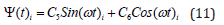
It may be noted here that we have used a slightly different form of FE-modelling for the prototype FRS, in contrast to ensemble link model that was discussed in sub-section 4.1. Thus, FEA-results for the deflection hue of the ensemble FRS (in the form of cantilever beam), as obtained in Figure 17-19b are different from the FEAresults of Figures 20-30. The crux of this difference in results is the modelling of revolute joints under FE-environment and segregation of the FRS-links and FRS-base. Besides, we have treated the in-situ vibration analysis of the prototype FRS as a dynamic phenomenon and used the analytical formulation suitably. We have used celebrated Euler-Bernoulli beam theory for the FE-based dynamic analysis of the prototype FRS. We have assumed a generic model for the end-displacement of any link of the prototype FRS that can be separated into two parts, respectively dependent on position and time as shown below:

were, λ (x, t) i: overall displacement of the ith. link of the prototype FRS; Ʌ(x)i: component of the displacement as a function of position for the ith. link of the prototype FRS and Ψ(t) i: component of the displacement as a function of time for the ith. link of the prototype FRS. The governing equation that was used for estimating these two components of displacement under FEA to ensure simple harmonic motion of the corresponding FRS-link under in-situ vibration is presented below:
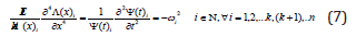
where, E: Young’s modulus of the material of fabrication of the prototype FRS; I: Moment of inertia of the ‘beam’ (i.e., FRS-link); A: Cross-sectional area of the ‘beam’; k: Linear mass density of the ‘beam’ (= ρ A ; ρ : material density); ω : Frequency of in-situ vibration of the ‘beam’. Now, segregation of the position variable of eqn. 7 will lead to the following FE-equation:
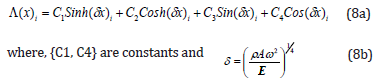
However, the pattern of deflection hue, as obtained through FEA (refer Figures 21-30) gets produced through analytical computation of the deflection of the individual elements of each of the FRS-link at any time-instant, ‘t’. The final expression for the deflection hue can thus be extrapolated from eqn. 8a in the following form:

The cumulative effect of the infinitesimal deflections at timeinstant
‘t’, as shown in eqn. 9 is vital for the FEA, wherein ‘k’ spans
out from the first element of the FEA (belongs to the FRS-1st.
link) to the last element of the FEA that falls under the ith. link of
the prototype FRS. The pattern of the deflection hue, inclusive of
buckling effect, is being governed by the pair of sinusoidal functions
as well as two hyperbolic functions, as detailed out in eqns. 8a & 9.
Now, so far, the time variable is concerned, we can get the
following extraction of eqn. 7, as used in FEA:
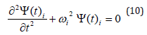
The FEA solution for eqn. 10 will be:
where, C5 and C6 are constants.
Finally, the combined FE-equation for the displacement of the prototype FRS becomes:

where, the constants {C1, C2, C3, C4} can be obtained from the boundary conditions and {C5, C6} are obtainable from the initial conditions under the FEA. Thus, we can conclude that the combined effect of deflection & vibration will be prudent with more number of joints in the flexible robotic arm. To add to this situation, this in-situ vibration gets boosted up when the payload is attached to the gripper of the FRS. The conjugate effect will culminate in higher dimensionality of the output response. With this backdrop, the design intricacy as well as strength of the joint has been validated through FEA.
FEA-based Analysis of Rheological Parameters Modelling Semantics
We will invoke FEA-based analysis for studying the timespanned
effect of three prime rheological parameters, relevant for
the actuation of the prototype FRS. These parameters are
a) linear bending stress
b) total deflection
c) torsional bending stress
As part of the first stage, we will study the deformation pattern
in the links of the prototype FRS and perform FEA-based numerical
analysis of bending stresses. Afterwards, we will study the pattern
of bending stress as well as total deformation of the base subassembly
(external housing) of the prototype FRS. As the prototype
FRS has a maximum reach of 1500 mm distributed over three
links, a coupled action of bending stress, near-buckled deflection,
torsional stress and finally, in-situ vibration do crop in because of
the self-weight of the links. This FEA-based rheological analysis
of the prototype FRS was carried out using FEAST® software,
beginning with modeling of the links & joints. The said FE-model
of the prototype FRS was developed & analyzed by considering
maximum planar reach of 1500 mm and total system-weight of 18
kg (using factor of safety of 2) for the assessment of bending and
torsional stresses as well as natural frequencies of vibration. Figure
31 presents the FEA-model of the prototype FRS including gripper
using FEAST® (‘ensemble link’ and ‘distributed links with gripper’
form). All the three links of the prototype FRS were modeled with
hollow circular cross-section, having outer & inner diameters as 10
mm. & 7 mm. respectively. The segmental portions of the ensemble
link have been indexed as ‘L1’ (for 1st. link), ‘L2’ (for 2nd. link) & ‘L3’
(for 3rd. link) in Figure 31.
Figure 31: Finite Element Model of the Ensemble Link & Distributed Links with Gripper of the Prototype FRS.

Background of FE-Modelling using ‘Ensemble Link’ Model and Summary of Results
The FE-modelling of the prototype FRS was attempted in FEAST® for both 1-D as well as 2-D analysis and accordingly, different sets of FEA results obtained for two of the rheological parameters, namely: total deflection and bending stress. The cross section of the FRS-link (CRFP tube) was assigned as a ‘physical property’ to the solver in 1-D analysis. Both types of FEA were carried with in two situations, viz. i] without the counter-balancing mechanism, i.e., suspension wire & ii] with the fixation of counter-balancing mechanism. The reaction force was also calculated to ensure force balance at the fixed locations, i.e., the ‘fixed end’ (refer Figure 31) and the location where the suspension wire is tied up with the first link (refer ‘E’ of Figure 9). Table 4 summarizes the FEA results for total deflection and bending stress of the prototype FRS under 1-D as well as 2-D analysis done in FEAST®. We have assumed diameter of the suspension wire as 1.5 mm and the suspension are connected at a distance of 800 mm from the fixed support of the FRS-first link. The length of the ‘ensemble link’ of the prototype FRS was taken as 1400 mm for the analysis.
[§: range of result is due to variation in mesh; ♠: Analytical
solution of bending stress in hollow pipe: 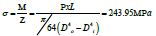 ]
]
Table 4: Summary of FEA Results for the Prototype FRS using Ensemble Link Model.

It may be noted that the crux of the FEA for the bending stress
is the modelling of the ‘ensemble link’ as hollow CFRP tube, which
also resembles a long pipe (for analytical solution). Figure 32 shows
the cut section of the hollow cylindrical pipe, made up of CFRP that
was used for the modelling in FEAST®.
As illustrated in Figure 32, the force is applied at center of the
hollow pipe with the help of rigid links in case of 2D modelling in
FEAST®. The rigid links provide the desired flexibility to define the
force and distribute it over the circumferential nodes easily. This
technique of modelling was achieved by generating a center node,
known as the master node and connecting circumferential nodes
to it that act as slave node(s). The details of these analyses will be
described in the following sub-sections.
Figure 32: FEAST®-Screenshot of the Cut–section of the Hollow Cylindrical CFRP Tube Resembling Ensemble Link of the FRS.

Analysis of Bending Stress using ‘Ensemble Link’ Model
Figure 33a: FEA Results for the Bending Stress in Ensemble FRS-Link ab initio along: X-Y plane (1D model).

Figure 33b: FEA Results for the Bending Stress in Ensemble FRS-Link ab initio along: Z-axis (2D model).

We have analyzed the distribution of bending stress in the
ensemble link of the prototype FRS along the X-Y plane as well as
along Z-axis, using two variants of FE-modelling in FEAST®. Figure
33 shows the screenshot of the corresponding FEA results, wherein
variation of bending stress (in MPa) of the FRS can be noted, e.g., at
the ‘fixed end’ &’gripper end’. In order to add contrast to the said
FEA, we have analyzed the bending stress using 1D model in Figure
33a vis-à-vis 2D model of the same in Figure 32b, using pre-assigned
mesh properties. The bending stress in 1D model is represented
by stress along X-Y plane as shown in Figure 33a. Corresponding
screenshot for the bending stress along z-axis (‘Sigma-Z’: active in
the plane of deflection of the FRS-link) is shown in Figure 33b, as
per the thematic of 2D model. The results are in-situ ab initio type
and symbolize the stress distribution in the FRS-links prior to the
fitment of the counter-balance metal wire in the overall assembly
(assuming ensemble FRS-link of length 1400 mm).
This is, in fact, an important facet of the bending stress analysis
that helps us to get an overall idea about the level of stress that
will be exerted on the prototype FRS in absence of counter-balance
measure to harness in-situ vibration of the system. We can observe
that the maximum value of the bending stress on the ensemble FRSlink
is more under 2D modelling (287.813 MPa) than in 1D model
(237.471 MPa). The observation is true for the minimum values of
the bending stress as well. Irrespective of the type of analysis (1D
or 2D), mesh generation plays a crucial role in determining the FEA
results, which is again dependent upon the range of bending stress
with various levels. Figure 34 shows the screenshots of a separate
set of FEA for the bending stress of the FRS, in accordance with
the data of Table 4. The data of Table 4 amply show that bending
stress (along X-Y plane or around Z) gets reduced to a significant
extent with the incorporation of suspension-type metallic wire as
counter-balancing mechanism for the prototype FRS. In contrast to
the FEA results of Figure 33-35 illustrates the 1D model-based FEA
simulation results of the bending stress (in MPa) on the ensemble
FRS-link of length 1400 mm, after fitment of the counterbalance
metallic wire (cross-section: 1.5 mm dia.). As obtained from the
results of Figures 33-35, the predominant zone of high bending
stress prevails around the first link of the prototype FRS, which
gets moderately seasoned out due to the incorporation of the
counterbalance metallic wire.
Figure 34a: Alternate Set of FEA Results for the Bending Stress in Ensemble FRS-Link ab initio: 1D model.

Figure 34b: Alternate Set of FEA Results for the Bending Stress in Ensemble FRS-Link ab initio: 2D model.

Figure 35: FEA Results for the Bending Stress along X-Y Plane Induced in the Prototype FRS-Links after Suspension of Metal
Wire.
Note: FE-screenshots of 1D analysis have been illustrated since those are lower in comparison to the corresponding results for
2-D analysis.

Our novel design of the counterbalance mechanism has been successful in reducing the bending stress of the ensemble link from 237.741 MPa to 158.105 MPa and even lower value to 100.193 MPa. Prior to FEA, we have carried out analytical computation of bending stress and total deflection of the ensemble link so as to get a feel of the range of values that we need to deal with so far as buckling of the prototype FRS as well as its inherent vibration are concerned. As per the theoretical calculation, the bending stress ( b σ ) is evaluated as 150 MPa, considering a payload (W) of 800 gm acting at a distance (L) of 1400 mm. from the ‘fixed end’ of the prototype FRS. [Design data: outer diameter of ensemble link (D): 10 mm; inner diameter of ensemble link (d): 7 mm; b σ =M.y/I, where Bending Moment, M=W.L= 8x1.4 Nm = 11.2 Nm; Distance from the Neutral axis, y=5 mm; Moment of Inertia, I=π /64(D4-d4) =373mm4]. Likewise, total deflection of the ensemble link (δ ) is calculated as 280 mm. [Young’s Modulus of CFRP, Y=7x10⁴ MPa; δ =WL3/3YI, where W=8N; L=1.4 m; I=373mm4].
Analysis of Resultant Deflection using ‘Ensemble Link’ Model
It is to be noted that variation of bending stress in FRS-links is directly proportional to the maximum deflection of the same in real-time. Although bending stress is a significant contributor towards real-time natural vibration of the prototype FRS, cumulative deflection of the ensemble FRS-link is not negligible either, as per the FEA simulation. We have obtained the deflection of the ensemble link with counterbalance mechanism as 26.6604 mm in contrast to its ab initio value of 138.606 mm (refer Table 4: 1-D analysis). We have analyzed the resultant deflection of the prototype FRS assuming ‘Ensemble Link’ architecture with the help of 2D model in FEAST®. Figure 36 illustrates the FEA-screenshots of the resultant deflection (‘T-RES’: 2-D analysis) of the ‘ensemble link’ (cantilever beam) of the prototype FRS ab initio, i.e., before fitment of the metallic wire as counterbalance mechanism, having maximum values of 142. 818 mm & 147.625 mm (refer Table 4 for details).
Figure 36: FEA Results for the Resultant Deflection of the Prototype FRS ab initio using 2-D Model.

Figure 37 shows the screenshots of the total deflection of the ensemble link of the prototype FRS under 1-D and 2-D analysis in FEAST® with the incorporation of metallic suspension wire as counter-balancing mechanism.
Figure 37a: FEA Results for the Resultant Deflection of the Prototype FRS after Suspension of Metal Wire: 1-D Model.

Figure 37b: FEA Results for the Resultant Deflection of the Prototype FRS after Suspension of Metal Wire: 2-D Model.

Analysis of Rheological Parameters using ‘Distributed Link’ Model
a) We will investigate three rheological parameters of the
prototype FRS using ‘Distributed Link’ model, namely: Bending
stress
b) Resultant deflection
c) Torsional stress
It is to be noted that FE-modelling under ‘Distributed Link’
semantic does have intrinsic features, with reference to modelling
of the revolute joints. It is interesting to note at this point that
FEA-results for bending stress (in X-Y plane: 1D model) does vary
quantitatively when we proceed for FEA with respect to separate
links & joints model of the prototype FRS, in lieu of ensemble link
model. Hence, after the preliminary level of theoretical estimation,
detailed FEA was carried out considering all the tare-weights in
the distributed links model of the prototype FRS (refer Figure 31).
Bending stress (in X-Y plane) was analyzed in distributed links
model of the prototype FRS (using 1D model in FEAST®), considering
payload at the free-end and tare-weights of all three links acting
at the respective mid-points of the respective links (symbolizing
center of gravity). Figure 38a illustrates the variation of bending
stress (in X-Y plane) of the prototype FRS with distributed links
before suspension of the metallic wire, i.e., counter-balancing
mechanism. Corresponding FEA-results of the bending stress after
suspension of the metallic wire are presented in Figure 38b. Both of
these studies were made using 1D model in FEAST®.
Figure 38a: Bending Stresses Induced in the Links of the Prototype FRS: Before. Index: Stress values are in MPa; Loads Considerations- at point A – Self -weight of link 1; at Point B – Self-weight of link 2; at point C – Self-weight of link 3; at point D – Payload

Figure 38b: Bending Stresses Induced in the Links of the Prototype FRS: After Suspension of Metal Wire.

The distributed link model of the prototype FRS was also analyzed for maximum deflection in FEAST® software. Figure 39a illustrates the final posture of the prototype FRS-model under maximum deflection (combined X, Y, Z values in mm.: 1D model) before suspension of the metallic wire, i.e., counter-balancing mechanism. Corresponding FEA-results of the maximum deflectionposture of the prototype FRS after suspension of the metallic wire are presented in Figure 39b. It may be noted that after suspension of metallic wire in the links there is major change in the deflection and bending stresses that has been observed in FEA. The bending stress of the prototype FRS in distributed link model is reduced substantially from 211MPa to 143 MPa after incorporation of the counter-balancing metallic wire. Likewise, maximum deflection in distributed link model of the prototype FRS is reduced substantially from 471.8 mm to 97.9 mm after incorporation of the counterbalancing metallic wire.
Figure 39a: Maximum Deflection in the Links of the prototype FRS: Before.

Figure 39b: Maximum Deflection in the Links of the prototype FRS: After Suspension of Metal Wire.

Besides bending stress, a fair amount of torsional stress gets induced in the first link of the prototype FRS at specific timeinstants / condition because of the excessive link length. This stress needs to be reduced in order to avoid torsional failure of the first link and eventually, the entire FRS. Figure 40 shows the screenshot of the FEA-results on torsional stress generated in the first link of the prototype FRS (1D model: labelled as ‘AB’). The numerical values of the FEA are obtained by taking a factor of safety. As evident from Figure 40, maximum torsional stress is induced in link AB because of the load on 2nd and 3rd link and the payload. While 20.79 MPa is the maximum value of torsional stress induced in the link (at a particular point in the first link: not visible in the screenshot), the average value of the torsional stress that will be largely prevalent all over the FRs-structure is ~ 5.2 MPa. It may be noted that along with the computation of torsional stress, it is equally important to evaluate ‘angle of torsion’ from the point of view of failure analysis. The computed value of the angle of torsion ( φ ) is 0.666 radian or 38.150 under the maximum torsional stress of 20.79 MPa [Design data: outer diameter of FRS-1st. link (D): 10 mm; inner diameter of FRS-1st. link:5 MPa; torsional shear stress (τ ): 20.79 MPa and working formula used for the angle of torsion: φ = (2 τ. L)/ (D.G)].
Figure 40: Torsional Stress on the Links of the Prototype FRS.

Rheological Study on Two Critical Components
We will now explore the FEA on two critical components of the base sub-assembly of the prototype FRS, namely: i] Assembly Block or the 3D-printed Frame (refer part # 3 of Figure 8) and ii] Base Mechanism: Body Structure (refer part # 1, 19 & 20 of Figure 8 and part ‘G’ of Figure 9). It may be stated that Assembly Block is under significant axial compressive force and bending force. As mentioned earlier, assembly block contains two thrust bearings and two ball bearings with two plates at both ends. While the lower base of the assembly block is bolted to the base plate, the upper plate rests on the thrust bearings atop. On the other hand, body structure holds up all the gears, motors, shafts & bearings as well as links (partially). Due to these added masses, body structure always remains under severe bending & compressive force. Figure 41a presents the Free-Body Diagram of the assembly block under standard operating condition of the prototype FRS. Likewise, Free- Body Diagram of the body structure of the base mechanism is depicted in Figure 41b. Both of these force analyses will serve as the foundation for the subsequent FEA.
Figure 41a: Free-Body Diagram of: Assembly Block.

Figure 41b: Free-Body Diagram of: Body Structure of the Base Sub-assembly of the Prototype FRS.

The free-body diagram of Figure 41a assumes a total
compressive force of 50N (approx.) is acting on the upper surface of
the assembly block, where the thrust bearings rest. The other force,
causing bending effect is assumed to be 13N (approx.), which is a
resultant of forces due to tare-weights of the links, gripper, flexible
shafts etc. This force is assumed to be acting at the end of the first
link of the prototype FRS as that links is subjected to maximum
deflection & torsion. With reference to the free-body diagram of
Figure 41b, a compressive force of 180N is assumed to be acting
on the body structure, considering a factor of safety 2.0. The rest
of the compressive forces, shown in Figure 41b, viz. 2.18N, 1.67N &
10N, correspond to the self-weight of the 1st., 2nd. & 3rd. links of the
prototype FRS respectively (inclusive of weights of flexible shafts,
gripper & payload as applicable). The rheological study of the
assembly block was carried out through FEA for two parameters,
namely: a] equivalent stress & b] total deformation. The said FEA
was done using the following inputs:
a) Material: abs
b) Modulus of elasticity: 2x10⁹ n/m2
c) Poisson’s ratio: 0.394
d) Shear modulus: 3189x105 n/m2
e) Density: 1020 kg/m3
f) Tensile ultimate strength: 3x10⁷ n/m2
g) Tensile yield strength: 29 mpa
h) Compressive yield strength: 7.5 mpa.
Figure 42a illustrates the FEA-screenshot for the equivalent
stress of the assembly block and the same for total deformation is
presented in Figure 42b. We can find that while maximum stress is
developed near the anchoring holes of the assembly block, the top
face of it is subjected to maximum deformation, spread out evenly
over the diametrically opposite ends.
Figure 42a: Rheological FEA-based Study of the Assembly Block of the Prototype FRS: Equivalent Stress.

Figure 42b: Rheological FEA-based Study of the Assembly Block of the Prototype FRS: Total Deformation.

In a similar way, rheological study of the body structure of base mechanism was carried out through FEA for equivalent stress & total deformation. The said FEA was carried out using the following inputs: i) material: steel; ii) modulus of elasticity: 2x10⁵ MPa; iii) Poisson’s ratio: 0.3; iv) shear modulus: 7692.3x107 N/m2; v) density: 7850 kg/m3; vi) tensile ultimate strength: 460 MPa; vii) tensile yield strength: 250 MPa & viii) compressive yield strength: 250 MPa. Figure 43a illustrates the FEA-screenshot for the equivalent Von-Mises stress of the body structure and the same for total deformation is presented in Figure 43b. The FEA-screenshot of Figure 43a shows that maximum stress of 498.77 MPa is developed near the through-holes of the body structure that are meant for the passage of the ball screw & guide rods. Likewise, we can find from Figure 43b that the top and side portion of the structure bears the maximum deformation of ~ 0.7278 mm, spread out evenly over the surfaces marked.
Figure 43: Rheological FEA-based Study of the Body Structure of the Prototype FRS: a] Equivalent Stress & b] Total Deformation.

Hardware Manifestation of The Prototype Flexible Robotic System
The prototype FRS, namely, ‘PAR: beta version’ was achieved successfully in working condition after the attainment of three ‘test-bed’ hardware of the same. These ‘test-beds’ are very crucial in terms of design validation, manufacturing, integration of servomotor & drives, transmission system via flexible shafts, functioning of mini-gripper and finally, the control system. There were many challenges before the hardware manifestation and customization of our system added difficulty to a significant extent. In order to tackle this problem of hardware development of the final prototype, we decided to branch out the realization process in the form of ‘test-beds’ for in-depth testing of the system components as well as sub-assemblies. It may be mentioned that we focused with each of these ‘test-beds’ with few pre-set goals and attempted to realize those as successfully as possible. Naturally, the development of these ‘test-beds’ are chronological and pitfall of one ‘test-bed’ helped us to improve the development of the next ‘testbed’. This learning process eventually became instrumental for the final prototyping of the system and its performance evaluation. We will now describe the details of the hardware realization of these ‘test-beds’ as well as the final prototyping. We will also highlight the salient attributes of the system controller of the final prototype.
Development of the Hardware of the First ‘Test-bed’
Figure 44: Photographic View of the Phase-I Hardware of the First Testbed of the FRS having Two Links.

Figure 45: Photographic View of the Phase-II Hardware of the First Testbed of the FRS with Additional Support at the Base.

The hardware manifestation of the maiden ‘test-bed’ of
the designed FRS was carried out in two phases. In phase-I, we
developed the backbone structure of the test-bed FRS using plain
carbon steel & aluminum as the material of fabrication of the
links and joints respectively. This phase was more of a design
realization, and we performed several iterations in order to attain
dynamic stability of the system. However, we limited our ‘testbed’
development with two links only, interspaced by a revolute
joint. The prime intention of our study was to have a first-hand
feel of the flexible manipulator having more than one link. It may
be mentioned that apart from fabrication of the two-link flexible
manipulator, hardware of the mini-gripper (as stand-alone unit)
too underwent minor modifications in this phase, although it was
not interfaced with the two-link flexible manipulator ‘test-bed’.
Figure 44 shows the photographic view of the developed hardware
of the first ‘test-bed’ of the prototype FRS, as part of phase-I.
The phase-I hardware of the first ‘test-bed’ of the FRS was
accomplished in three functional phases, namely: a) fabrication of
the links; b) manufacturing of the revolute joint assemblies and c)
construction of the base assembly having basic tripod mechanism.
It may be stated that the first functional phase of link fabrication
was very crucial as it was the basic learning episode for the final
prototype. In order to get an insight to the fabrication process,
we decided to manufacture the links using steel as technology of
machining of steel is well-known. Likewise, revolute joints were
fabricated using aluminium just to ensure light-weight assembly.
The base assembly was made with various ad-hoc features
devoid of ergonomics as well as aesthetics. Besides, the tripod
mechanism was not included in the ‘test-bed’ in its full form (i.e.,
height adjustment), as our prime intention for this phase of the
hardware was ensuring smooth jerk-free planar motion of the
two-link flexible manipulator. The customization of the flexible
shaft, as stated earlier, also plays crucial role in this ‘test-bed’. The
phase-II hardware of the first ‘test-bed’ was made with more design
investigation on the indigenously fabricated additional support for
the first link towards preventing unwarranted sagging. This phase
was critical as well as decisive for an understanding of the nature
of natural frequency of vibration of the test-bed FRS. Figure 45
illustrates the photographic view of the phase-II hardware, with
inset view on the disposition of two additional collar-and-boss type
supports.
Development of the Second ‘Test-Hardware’ of the Prototype FRS
Both phases of the maiden ‘test-bed’ were made only for
physical validation of the two-linked flexible manipulator system
towards realizing the prototype design ensemble. The experience
gathered therefrom led us to the development of the second ‘test
hardware’ of the prototype FRS, made up of CFRP tubes. The
second ‘test hardware’ had three links, interspaced by two revolute
joints, having nearly the same dimensions of the final prototype.
However, wed did not interface the mini gripper in this hardware
in order to ensure better concentration over the real-time control
dynamics of the links & joints, made up of the final selected material
for manufacturing, namely, CFRP. The zoomed view of the ‘test
hardware’ can be seen in Figure 46a, highlighting two flexible shafts
separately and two inter-spaced revolute joints. The photographic
view of our second ‘test hardware, i.e., the final three-linked serialchain
flexible manipulator system fitted with counter-balancing
mechanism, is shown in Figure 46b.
It may be noted that we have introduced the preliminary form
of counter-balancing mechanism in this test hardware as it was felt
crucial for harnessing the in-situ vibration of the slender three-link
FRS. The process of improvisation from ‘collar & boss-type dual
support’ (refer Figure 46a) to ‘prop & wire-driven counter-balancing
mechanism’ (refer Figure 46b) is a big hardware leap towards
combating vibration. The effect of this innovative mechanism was
proven to be highly effective in the third ‘test hardware’ and in ‘final
prototype’. This test hardware was also instrumental in effective
lay outing and hardware interfacing of two long indigenously
developed flexible shafts for the smooth transmission of power to
the revolute joints (J2 & J3).
Figure 46: Photographic View of the Second ‘Test Hardware’: a] Zoomed View & b] Final System with Counter-balancing Mechanism.

Development of the Third ‘Test-Hardware’ of the Prototype FRS
In the next phase of the development of the ‘test hardware’, we
incorporated the following attributes, namely:
a) Streamlining the alignment of the flexible shafts
b) Improvisation of the second revolute joint with worm-worm
wheel pair
c) Betterment of the design of the counter-balancing mechanism
d) Physical augmentation of the mini gripper at the end of the third
link
The practical experience of developing previous two ‘test
hardware’ has led us to take up the hardware of the third testbed
using CFRP as the material of fabrication for the link. The second
joint was added with a worm-worm wheel pair for improved
dynamics. Figure 47 illustrates the photographic view of the third
‘test hardware’ of the prototype FRS, fitted with mini gripper. It is
to be noted that base and tripod assembly (subsuming joint 1) of
the third ‘test hardware’ is same as that of the previous hardware.
The in-situ trembling of the ‘test hardware’ was arrested to a
large extent by streamlining the alignment of the flexible shafts by
using re-oriented placement of the joint-servomotors. This is an
important contribution of the third test hardware that has led to
fine-tuning of the final prototype of ‘PAR: beta version’. Figure 48
illustrates the photographic view of the alignment of the flexible
shafts and corresponding drive-motors of the third ‘test hardware’,
in two different snapping postures.
Figure 47: Photographic View of the Third ‘Test Hardware’ of the Prototype FRS.

Figure 48: Photographic View of the Alignment of the Flexible Shafts and Drive-Motors of the Third ‘Test Hardware’.

Improvisation of the design of the worm-worm wheel-based revolute joint was attained to a good level of engineering excellence, backed up by aesthetically impressive design of the exterior in the present ‘test hardware’. The prime focus of this design-upliftment was related to the compactness of the assembly. Figure 49a shows the partial view of the hardware with locations of the joints marked, i.e. ‘I”: 2nd. joint with worm-worm wheel pair and ‘II’: 3rd. joint with usual structure. The disposition of this novel joint under two different postures of the mating links of the ‘third test hardware’ is illustrated in Figure 49b. Manufacturing-level design of the counterbalancing mechanism was improvised to a satisfactory as well as aesthetically pleasant format in this version of the ‘test hardware’. The fundamental domain of this betterment was related to the ergonomic design of the central prop and the support base. Figure 50 brings out the relative improvision of the counter-balancing mechanism from ‘second test hardware’ to the ‘third test hardware.
Figure 49: Improvisation of the Design of the Worm-Worm Wheel-based Revolute Joint of the Third ‘Test Hardware’.

Figure 50a: Improvisation of the Counter-balancing Mechanism from: Second Test Hardware

Figure 50b: Improvisation of the Counter-balancing Mechanism from: Third Test Hardware.

Nonetheless, the most significant aspect of the third test hardware is the interfacing of the mini gripper with several criticalities due to instrumentation. Figure 51a shows the frontal view of the mini-gripper, as attached to the third link of the test hardware and the back-side view of the mini-gripper, holding an object (syringe) is elucidated in Figure 51b.
Figure 51: Hardware of the Mini-Gripper of the ‘Third Test Hardware’ of Prototype ‘PAR’: [a] Frontal View: [b] Backside View.

Development of the Final Prototype of the FRS (PAR: Beta Version)
Mechanical Hardware
The expertise gained through the hardware manifestation of the ‘test beds’ was instrumental in detailing out the next sojourn for building up the ab initio hardware of the final prototype FRS, using CFRP tubes for the construction of the links. Besides, we could attain a successful realization of the novel design of the revolute joint with worm-worm wheel mechanism. All the three links of the prototype FRS (‘PAR: beta version’) were made up of lightweight CFRP having more strength to weight ratio. The final phase of the development of ‘PAR: beta version’ was empowered with the following attributes, namely: a] improvisation of the both second & third revolute joint with worm-worm wheel mechanism; b] professional look for the tripod mechanism and improvement of the base assembly and c] betterment of cable routing & allied instrumentation. We have found much better performance in gripping as well as vibration harnessing paradigms in the third test hardware, due to the augmentation of worm-worm wheel pair in the second joint. Based on our finding in the third test hardware, both second as well as third revolute joint of the final prototype were added with worm-worm wheel mechanism for improved dynamics in real-time operation. Figure 52 illustrates the partial photographic view of the final prototype, highlighting efficient & high-performance joints and mini gripper in action, along with improvised wiring & cable routing.
Figure 52a: Photographic View of the Final Prototype FRS (‘PAR’) in Grasp Action: Frontal View.

Figure 52b: Photographic View of the Final Prototype FRS (‘PAR’) in Grasp Action: Zoom-in View.

Figure 53: Hardware of the Tripod Stand of the Prototype FRS (‘PAR’): [a] CAD Model; [b] Working Model. Index: A: Ball Screw; B: Ball Nut; C: Stand. below the figure

CFRP being very lightweight material with higher strength to
weight ratio, the final prototype FRS could achieve the pinnacle of
very low tare weight. This hardware manifestation took place after
detailed analysis of the FRS design, taking into considerations all
the factors affecting inherent vibration, deflection, bending stresses
and torsional strength of the links, over and above carried out in
earlier ‘test -bed hardware’. A substantial up-gradation of the base
assembly as well as ensemble tripod stand was carried out in
the final prototype, which played a crucial role in combating the
vibration through the smooth & controlled functioning of the tripod
stand. It may be noted here that the backbone of the final prototype
FRS is the tripod sub-assembly, comprising of a customized
recirculating ball screw-nut mechanism, which sustains all the tare
weight of the ensemble system and allows jerk-free up and down
motion. The importance of this ball screw mechanism is envisaged
in easy manoeuvrability of the entire FRS as per the requirement of
the application. Figure 53b illustrates of the photographic view of
the developed tripod stand, comprising the ball screw mechanism
with three guide rods fitted on the base stand in contrast to its CAD
model (refer Figure 53a).
Figure 54 shows the final assembly of the tripod stand & base
of the prototype FRS, in three different views, namely: side view,
frontal view and reverse side view (i.e., view from the manipulatorlink
end).
Figure 54a: Tripod Stand & Base Assembly of the Prototype FRS: Side View.

Figure 54b: Tripod Stand & Base Assembly of the Prototype FRS: Frontal View.

Figure 54c: Tripod Stand & Base Assembly of the Prototype FRS: Reverse Side View.

With the fine-tuning of various hardware elements and subassemblies of the prototype FRS, the complete working prototype of “PAR: beta version” was realized. Figure 55 presents the photographic view of the prototype FRS (final assembly of PAR: beta version). The working prototype PAR was successfully tested for a variety of gripping actions in real-time, with objects of different dimensions (refer YouTube video of the prototype ‘PAR’ at: https:// youtu.be/Nwbt94E8Tds)
Figure 55: Photographic View of the Final Assembly of the Prototype FRS: ‘PAR’.

Controller Hardware
The device controller for the prototype FRS has been designed
using National Instrument®-make my RIO®, which has an easy
handshaking with the D.C. servomotors (for the joint actuations) as
well as the motion controller & motion manager software. Besides,
it has built-in Wi-Fi and a faster processor with enhanced memory.
My RIO® runs on a Linux-based real-time operating system, which
enables it to piggyback LabVIEW® code on it, besides multithreading
to have some parallel operations. The FPGA on my RIO® allows
high-speed data acquisition and/or filtering at a much faster rate
(~40MHz clock rate). We have used LABVIEW®-based graphicalmode
programming for being interfaced with the motion controller
& my RIO®. The developed Graphical User Interface (GUI) makes
uniform and intuitive procedures possible that are independent of
the device family and interface used. Although my RIO® - LabVIEW®
tuple is effective as GUI, but it lacks fine-tuning of the joint rotations
and forward kinematics of the prototype FRS (‘PAR: beta version’).
In order to imbibe more flexibility, open-source electronic
prototyping platform, Arduino® was used for controlling the jointmotors
of the prototype FRS. In fact, Arduino Mega™ had been our
preferred development board for controlling the prototype flexible
robot. MATLAB®-based indigenous code was compiled thereof and
was interfaced with the Arduino® board. Usual trial & error-based
debugging of Arduino® gets reduced to a significant extent due to
the augmentation of MATLAB® code that can be edited under a
user-friendly GUI. The MATLAB® program involves various subroutines
& call-functions to send commands to the motors for joint
rotation as well as graphical plot of the alteration of configuration
of the prototype FRS. Atmega2560™ is the microcontroller chip of
the Arduino Board, which is responsible for coordinating all the
major joint actuations of the prototype FRS. The high-performance,
low-power Microchip 8-bit AVR RISC-based microcontroller gets
augmented with 8KB SRAM, 4KB EEPROM, 86 general purpose I/O
lines.
The device achieves throughput of 16 MIPS at 16 MHz and
operates between 4.5-5.5 volts. Atmega2560™ is a hundred pin
IC, out of which only 10 pins have been used in the present setup
of the prototype FRS. The microcontroller chip has been invoked
effectively in the device controller with indigenous program code.
The source code elements have been devised under two broad
groups, namely: a] variables & b] functions. Since the prototype FRS
consists of three movable links that are independent of each other’s
movement, we had to send commands for the motion of each link
separately through distinct angle values. Accordingly, the developed
program code inherits a cluster of four variables that accepts
the input-angles of the four-links of the prototype FRS, namely:
Gripper Link Angle, Middle Link Angle, Base Angle and Head Angle.
We need to know the real-time rotational speeds (rpm) of the
servomotors in order to calculate the said ‘angles of movement’
of the FRS-links. The refinement of user-editable control program
and iterations thereof contributed significantly in achieving the
performance mantle of the prototype ‘PAR: beta version’. The finer
details of the control program, controller architecture and software
programming of prototype PAR will be reported elsewhere.
Conclusions
Novel design and developmental paradigms of three-link three-joint serial-chain FRS prototype along with three prior test hardware have been reported in this paper. Distinctive and unique design of serial-chain multi-link FRS with novelty of revolute joint has been reported in context to the testbed & prototype hardware. We have investigated the design-basis for reducing the inherent vibration of the system and implemented the firmware in an elegant way. As a follow-up to the evaluation of total elemental stresses in links & joints of the prototype FRS, we have studied details of vibration signature & associated deflection, bending & torsional stresses of the FRS-links. Finite element analysis of the links with ensemble FRS assembly has been carried out in order to overcome in- situ vibration of FRS and deflection of the links. Nonetheless, specifically in case of links, torsional analysis was carried out in order to make it more torsional rigid. Apart from this, modal analysis for vibration and subsequent deflection was checked too. FE-simulation thereof has helped us in pin-pointing the support locations & related kinetics between the base-assembly & first link. Indigenous design of a micro-gripper is another novelty in the prototype FRS because of its lightweight disposition in contrast to its load carrying capacity. Hardware manifestation of the prototype FRS with micro-gripper has been successful and it is entrusted that the present version of the FRS will serve as an effective solution to low-payload material handling tasks in real-time. The paradigms earned through modelling & hardware manifestation of ‘PAR: beta version’ can be benchmarked that has made the foundation for the deployable firmware for Patient Assistant Robot in near future.
Acknowledgement
Authors acknowledge the help rendered by Shri Shubham Chaudhary, CAE Division, SVR Infotech, Pune, India in performing a few of the Finite Element Analysis on material selection and initial design of the prototype FRS. Sincere thanks are due to Shri Aditya Rauniyar, SRMIST, India and intern scholar at SVR Infotech, Pune, India towards performing design analysis of the base sub-assembly of the prototype FRS. The engineering service and technical assistance rendered by Shri Pankaj Pandit, Shri Shreyash Gajlekar, Shri Amit Deka & Shri Prathamesh Warude of Robotics Division, SVR Infotech, Pune, India is deeply acknowledged.
References
- M Benosman, G Vey (2004) Control of Flexible Manipulators: A Survey. Robotica 22(5): 533-545.
- NC Singer, WC Seering (1990) Preshaping Command Inputs to Reduce System Vibration. Journal of Dynamic Systems, Measurement & Control- Transactions of the ASME 112(1): 76-82.
- A R Fraser, RW Daniel (1991) Perturbation Techniques for Flexible Manipulators. Norwell MA Kluwer.
- ZH Luo (1993) Direct Strain Feedback Control of a Flexible Robot Arm: New Theoretical & Experimental Results. IEEE Transactions on Automatic Control 38(11): 1610-1622.
- Wen Chen (2001) Dynamic Modelling of Multi-link Flexible Robotic Manipulators. Computers & Structures 79(2): 183-195.
- B Subudhi, AS Morris (2002) Dynamic Modeling, Simulation and Control of a Manipulator with Flexible Links & Joints. Robotics and Autonomous Systems 41(4): 257-270.
- Avello A, Garcia de Jalon J, Bayo E (1991) Dynamics of Flexible Multibody Systems Using Cartesian Co-ordinates and Large Displacement Theory. International Journal of Numerical Methods in Engineering 32(8): 1543-1563.
- Agrawal O, Shabana A (1986) Application of Deformable body mean axis to flexible multibody system dynamics. Computational Method in Applied Mechanics and Engineering 56(2): 217-245.
- Song J, Haug E (1980) Dynamic analysis of planar flexible mechanisms. Computational Method in Applied Mechanics and Engineering 24(3): 359-381.
- V Feliu, JA Somolinos, A Garcia (2003) Inverse Dynamics based Control System for a Three Degrees-of-freedom Flexible Arms. IEEE Transactions on Robotics & Automation 19(6): 1007-1014.
- V Feliu, F Ramos (2005) Strain Gauge based Control of Single-Link Flexible Very Light Weight Robots Robust to Payload Changes. Mechatronics 15: 547-571.
- Fraeijs de Veubeke B (1976) The dynamics of flexible bodies. International Journal of Engineering Science 14(10): 895-913.
- Jianhua Zhang, Ying Tian, Minglu Zhang (2014) Dynamic Model and Simulation of Flexible Manipulator based on Spring & Rigid Bodies. Proceedings of the 2014 IEEE International Conference on Robotics & Biomimetics (‘ROBIO-2014’) pp: 2460-2464.
- VG Moudgal, WA Kwong, KM Passino, S Yurkovich (1995) Fuzzy Learning Control for a Flexible-link Robot. IEEE Transactions on Fuzzy Systems 3(2): 199-210.
- NC Singer, WC Seering (1990) Preshaping Command Inputs to Reduce System Vibration. Journal of Dynamic Systems, Measurement & Control- Transactions of the ASME 112: 76-82.
- YP Chen, HT Hsu (2001) Regulation & Vibration Control of an FEM-based Single-link Flexible Arm using Sliding-mode Theory. Journal of Vibration Control 7(5): 741-752.
- H Tjahyadi, K Sammut (2006) Multi-mode Vibration Control of a Flexible Cantilever Beam using Adaptive Resonant Control. Smart Materials and Structures 15(2): 270-278.
- Juan R Trapero Arenas, Mamadou Mboup, Emiliano Pereira Gonalez, Vicente Feliu (2008) Online Frequency and Damping Estimation in a Single-Link Flexible Manipulator based on Algebraic Identification. Proceedings of the 16th. Mediterranean Conference on Control & Automation (IEEE) Franco pp: 338-343.
- Emiliano Pereirea, Summet Sunil Aphale, Vicente Feliu, SOR Moheimani (2011) Integral Resonant Control for Vibration Damping and Precise Tip-positioning of a Single-link Flexible Manipulator. IEEE/ ASME Transactions on Mechatronics 16(2): 232-240.
- Chun Hon M, Turner James D, Juang Jer Nan (1985) Disturbance Accommodating Tracking Maneuvers of Flexible Spacecraft. Journal of the Astronautical Sciences 33(2): 197-216.
- Gupta Narendra K (1980) Frequency-Shaped Cost Functionals: Extension of Linear-Quadratic-Gaussian Design Methods. Journal of Guidance and Control 3(6): 529-335.
- Juang Jer Nan, Turner James D, Chun Hon M (1985) Closed-Form Solutions for Feedback Control with Terminal Constraints. Journal of Guidance and Control 8(1): 39-43.
- Warude P, Patel M, Pandit P, Patil V, Pawar H, et al. (2019) On the Design and Vibration Analysis of a Three-Link Flexible Robot Interfaced with a Mini-Gripper. Lecture Notes in Mechanical Engineering: Recent Trends in Wave Mechanics and Vibrations. Springer pp: 29-45.
- Rauniyar A, Roy D, Pandit P, Atpadkar V (2018) Design Model for the Drive & Actualtor of the Test Set-up of a Novel Flexible Robotic System. Proceedings of the 2018 IEEE International Conference on Computational Intelligence and Computing Research (IEEE-ICCIC-2018) Madurai, Tamil Nadu, India.
- Harshal Pawar, Chinmay Nate, Manoj Patel, Pankaj Pandit, Vikram Patil, et al. (2019) Design, Dynamic Simulation and Test-run of the Indigenous Controller of a Multi-Gripper Revolute Robot by Minimizing System Trembling. Lecture Notes in Mechanical Engineering: Recent Trends in Wave Mechanics and Vibrations, Springer pp: 47-60.
- Roy Debanik (2019) Towards the Control of Inherent Vibration of Flexible Robotic Systems and Associated Dynamics: New Proposition and Model. International Journal of Robotics Research, Applications and Automation 1(1): 6-17
- Debanik Roy (2019) Control of Inherent Vibration of Flexible Robotic Systems and Associated Dynamics. Lecture Notes in Mechanical Engineering: Recent Trends in Wave Mechanics and Vibrations Springer.
- Roy Debanik (2020) Design, Modeling, and Indigenous Firmware of Patient Assistance Flexible Robotic System-Type I: Beta Version. Advances in Robotics and Mechanical Engineering 2(3): 148-159.


-

Mark E Smith
Bio chemistry
University of Texas Medical Branch, USA -

Lawrence A Presley
Department of Criminal Justice
Liberty University, USA -

Thomas W Miller
Department of Psychiatry
University of Kentucky, USA -

Gjumrakch Aliev
Department of Medicine
Gally International Biomedical Research & Consulting LLC, USA -

Christopher Bryant
Department of Urbanisation and Agricultural
Montreal university, USA -

Robert William Frare
Oral & Maxillofacial Pathology
New York University, USA -

Rudolph Modesto Navari
Gastroenterology and Hepatology
University of Alabama, UK -

Andrew Hague
Department of Medicine
Universities of Bradford, UK -

George Gregory Buttigieg
Maltese College of Obstetrics and Gynaecology, Europe -

Chen-Hsiung Yeh
Oncology
Circulogene Theranostics, England -
.png)
Emilio Bucio-Carrillo
Radiation Chemistry
National University of Mexico, USA -
.jpg)
Casey J Grenier
Analytical Chemistry
Wentworth Institute of Technology, USA -

Hany Atalah
Minimally Invasive Surgery
Mercer University school of Medicine, USA -

Abu-Hussein Muhamad
Pediatric Dentistry
University of Athens , Greece
