


Lupine Publishers Group
Lupine Publishers
ISSN: 2643-6736
Research Article(ISSN: 2643-6736) 
Gyroscopic Torques Acting on Crushing Mill Volume 1 - Issue 4
Received:January 22, 2019 Published: January 29, 2019
*Corresponding author: Ryspek Usubamatov, Department of Automation and Robotics, Kyrgyz State Technical University named after I. Razzakov, 420044, Bishkek, Kyrgyzstan
DOI: 10.32474/ARME.2019.01.000120
Also view in:


Abstract
Numerous mechanisms with rotating objects in engineering manifest gyroscopic effects, which mathematical models formulated on the law of kinetic energy conservation and the action of inertial torques. Known theories of gyroscopic effects are far from the practical result of the action inertial torques on the rotating objects. The new study demonstrates that the gyroscopic effects are the result of the simultaneous and interdependent action of the resistance and precession torques of rotating objects around different axes. The centrifugal and Coriolis forces are generated the first torques and the second one by the common inertial forces and the change in the angular momentum of the rotating mass of a spinning object. The principle of gyroscope effects has been applied in the crushing pendulum mills used for ore, seeds, etc., where the intense pressure is desired. The new principles of the action of internal and external torques on the crushing mill enable for the computing the actual forces that produce the work. This manuscript represents the mathematical model for the actual torques and power that manifest the crushing mill.
Keywords: Gyroscopic Effects; Inertial Torques; Crushing Mill
Introduction
Gyroscopic effects manifest at numerous rotating objects in engineering. Correct computing of and gyroscopic properties enables for the functioning of the gyroscopic devices in engineering. Since the Industrial Revolution published many gyroscope theories as well as many approaches and mathematical solutions that describe the gyroscope properties [1-4]. Numerous publications described the gyroscope effects and applications in engineering [5,6]. All of them describe gyroscope properties only in terms of the law of conservation of energy and the angular momentum. Nevertheless, the nature of gyroscope effects is more complex and known theories do not match the practice of gyroscopic devices [7-9]. Therefore, researchers continue to find true mathematical models of gyroscopic effects [10-14]. New research in the area of the gyroscope theory gives the new mathematical models for inertial forces acting on a gyroscope [15,16]. These publications demonstrate that on rotating objects act the several inertial forces of their mass-elements that express the resistance and precession torques. The centrifugal and Coriolis forces of the rotating masselements result in the resistance torques. The common inertial forces and the change in the angular momentum result in the precession torques. Table 1 represents the equations of the inertial torques acting on rotating objects. The action of the new inertial and external torques of the rotating objects should be considered for the mathematical modeling of the work of mechanism in engineering (Table 1).
Table 1: Internal inertial torques acting on a gyroscope.

Where i is the index for axis; J = (mR2/2) is the rotor’s mass moment of inertia around spin axis; m is the rotor’s mass; R is the external radius of the rotor; ωi is an angular velocity of precession of a spinning rotor around axis i and ω is an angular velocity of a spinning rotor; other components are as specified in Table 1. Analysis of the internal torques that represented in Table 1 demonstrates that their values of are different but proportionally depend on the mass moment of inertia of a rotor and its angular velocity as well as on the angular velocity of precession. These torques represent fundamental principles of the gyroscope theory. New mathematical models for the inertial torques can describe all gyroscope effects that manifest any rotating objects. This work represents the computing of the torques and power for the crushing mill based on the mathematical models for the inertial torques generated by the flywheel.
Methodology and Working Example
Figure 1: Crushing mill .

The principle of gyroscope effects has been applied in the crushing pendulum mills used for ore, seeds, etc., where the intense pressure is desired (Figure 1). The pendulum mill consists of a large steel pan in which two heavy conoidal flywheels of m = 400kg mass each roll on the bottom of the pan without slipping. The steel of the flywheel of the density ρ = 7545.2 kg/m3. The maximal and minimal radius of conoid about its axle is 0.3m and 0.15m respectively. The distance from the axis of rotation of the flywheel to its Centre of the mass is 0.6m, the angle φ of the conoidal flywheel is 30o. The flywheels revolve about a vertical shaft passing through the centre of the pan with the angular velocity of ωp = 60 rpm = 2π rad/s and with spinning about own axis of n = 30.0 rpm. The pan and flywheels designed with conic surfaces that enable to avoid intensive friction processes of two surfaces due to different tangential velocities of the flywheel edges. This friction process is unavoidable for the horizontal design of the pan. The two flywheels placed symmetrically about the shaft and rotated around own axes. The axes of flywheels are attached to the vertical shaft by means of couplings that permit them to have enough vertical motion to roll over uneven lumps in the pan. Figure 1 represents the general case of one flywheel where is considered the action of the gyroscope effects. Define the power required for the work of the crushing.
For simplicity of computing is accepted the form of the flywheel is the cylindrical disc. Acting forces on the running flywheel are the weight, centrifugal forces, Coriolis force and forces generated by the precession torques of the inertial force and angular momentum. The resulting torque acting on the bottom of the pan is presented by the following equation:
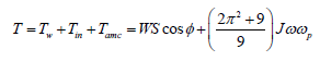
where T is the total moment of action the forces about the point
o; W is the weight of the flywheel; S is the length of axle (distanced
from the pivot to the centre of gravity); J is the mass moment of
inertia of the flywheel; ω is the angular velocity of the flywheel;
ωp is the angular velocity of the precession of the flywheel around
the vertical axis. Since by hypothesis the flywheel does not slip on
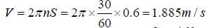
the plate of the pan, the angular velocity of the flywheel rotation is
defined by its tangential velocity. The average tangential velocity
of the rotation the flywheel about the axis of the pane is as follows

The mass moment of the flywheel inertia is
 where the mass of the cylinder m1 = πR12hρ =
π×0.152×0.3×7545.2 = 160kg and the mass of the conical ring
where the mass of the cylinder m1 = πR12hρ =
π×0.152×0.3×7545.2 = 160kg and the mass of the conical ring
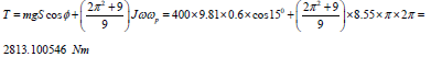
m2 = π(R22 - R12)hρ/2 = π×(0.32 - 0.152)×0.3×7545.2/2 = 240kg. The crashing torque is as follows
Total crashing force is F = T/S = /0.6 = 4688.500910 N. The
crushing force that gives the weight of the flywheel is FW = Wgcosφ
= 400×9.81×cos150 = 3790.2929416 N. The crushing force that
gives the gyroscopic torques of the flywheel is
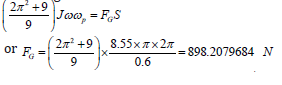
The force of the gyroscopic effect is 5.21 times less than the action of the flywheel weight. The resistance torques Tr generated by the centrifugal and Coriolis forces of the crushing wheel is represented by the equation in Table 1. The power required for the crashing process by two flywheels is calculated by the following equation P=2Frfw1+Trwp. Substituting defined parameters and initials data into this equation yield the following result:
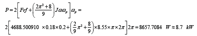
where r = 0.18 m is the radius of the conical flywheel at the point of the center mas, f = 0.2 is crashing coefficient, other parameters are as specified above. The crushing pendulum mill should be equipped with the electric motor of the power 8.7 kW.
Results and Discussion
New mathematical models for the inertial torques acting on the spinning objects enable for the developing of equations for the computing parameters of work for any rotating objects in engineering. The model for the inertial torques acting on the flywheel of the crushing mill is based on the action of the several inertial torques, the action of frictional forces and the weight components acting on the pan. The mathematical models for the computing the inertial torques generated by the flywheel enable for the demonstrating the physics of the crushing process and by the action of other well-known components. The models of the acting inertial torques show the new value of forces and the power for crushing process.
Conclusion
The numerous mechanisms in engineering contain rotating objects which manifest gyroscopic effects which analytical solutions for a long time represented the unsolvable problem. New analytical approach to the inertial torques acting on the rotating objects finely resolved all problems in the area of the rotating objects. Several inertial forces generated by the mass of the spinning objects act simultaneously and interdependently on the rotating objects that demonstrate the gyroscopic effects. The new mathematical models for the inertial forces acting on the rotating objects should be used for engineering computing of the working parameters of different mechanisms and machines. The action of the inertial torques generated by the masses of rotating objects demonstrated on the work of the crushing mill.
References
- MN Armenise, C Ciminelli, FV Dell’Olio, MN Passaro (2010) Advances in Gyroscope Technologies. Springer-Verlag Berlin and Heidelberg GmbH & Co. KG, Berlin.
- RF Deimel (2003) Mechanics of the Gyroscope, Dover Publications Inc. New York.
- H Weinberg (2011) Gyro Mechanical Performance: the most important parameter. Technical Article MS-2158, Analog Devices, pp. 1-5.
- DR Gregory (2006) Classical Mechanics. Cambridge University Press, New York.
- J Syngley, JJ Uicker (2002) Theory of Machines and Mechanisms, (3rd edn). McGraw-Hill Book Company, New York.
- MD Aardema (2005) Analytical Dynamics. Theory and Application. Academic/Plenum Publishers, New York.
- RM Jonsson (2007) Gyroscope precession in special and general relativity from basic principles, American Journal of Physics 75(5): 463.
- WC Liang, SC Lee (2013) Vorticity, gyroscopic precession, and spincurvature force. Physical Review D 87: 044024.
- E Butikov (2006) Inertial rotation of a rigid body. European Journal of Physics 27: 913-922.
- TJ Quinn, A Picard (1990) The mass of spinning rotors: no dependence on speed or sense of rotation. Nature 343: 732-735.
- L Zyga (2011) Gyroscope’s unexplained acceleration may be due to modified inertia. PhysOrg.com July 26.
- JE Faller, WJ Hollander, PG Nelson, MP McHugh (1990) Gyroscopeweighing experiment with a null result. Physical Review Letters 64, APS Journal 64(8): 825-826.
- K Kodama, M Adachi, K Kamimura, S Kurosu (2002) Gyroscopic Force Measuring System. Transactions of SICE 38(2): 117-123.
- A Ferrari (2006) Gyroscope’s Precession and the Principle of Equivalence. Annalen der Physik 501(5): 399-400.
- R Usubamatov (2018) Inertial Forces Acting on Gyroscope. Journal of Mechanical Science and Technology 32(1): 101-108.
- R Usubamatov, T Zhumaev (2018) Inertial Forces Acting on a Propeller of Aircraft. The Open Aerospace Engineering Journal 7(2018): 1-13.


-

Mark E Smith
Bio chemistry
University of Texas Medical Branch, USA -

Lawrence A Presley
Department of Criminal Justice
Liberty University, USA -

Thomas W Miller
Department of Psychiatry
University of Kentucky, USA -

Gjumrakch Aliev
Department of Medicine
Gally International Biomedical Research & Consulting LLC, USA -

Christopher Bryant
Department of Urbanisation and Agricultural
Montreal university, USA -

Robert William Frare
Oral & Maxillofacial Pathology
New York University, USA -

Rudolph Modesto Navari
Gastroenterology and Hepatology
University of Alabama, UK -

Andrew Hague
Department of Medicine
Universities of Bradford, UK -

George Gregory Buttigieg
Maltese College of Obstetrics and Gynaecology, Europe -

Chen-Hsiung Yeh
Oncology
Circulogene Theranostics, England -
.png)
Emilio Bucio-Carrillo
Radiation Chemistry
National University of Mexico, USA -
.jpg)
Casey J Grenier
Analytical Chemistry
Wentworth Institute of Technology, USA -

Hany Atalah
Minimally Invasive Surgery
Mercer University school of Medicine, USA -

Abu-Hussein Muhamad
Pediatric Dentistry
University of Athens , Greece
