Lupine Publishers Group
Lupine Publishers
Menu
ISSN: 2643-6736
Research Article(ISSN: 2643-6736) 
Direct Slicing and Optimization of Nurbs to Present the Slices with Closed Curves in Cranioplasty Implants Volume 4 - Issue 1
Charanpreet Singh Sidhu1*, and Zeinab El Sayegh2
- 1Faculty of Engineering and Applied Science, Ontario Tech University, Oshawa, Canada
- 2Department of Automotive and Mechatronics Engineering, Ontario Tech University, Canada
Received:June 26, 2023 Published: June 28, 2023
Corresponding author: Charanpreet Singh Sidhu, Faculty of Engineering and Applied Science, Ontario Tech University, 2000 Simcoe St N, Oshawa, ON, L1G 0C5, Canada
DOI: 10.32474/ARME.2023.04.000179
Abstract
This paper presents a method for direct slicing and optimization of NURBS (Non-Uniform Rational B-Spline) surfaces to generate closed curves for the fabrica-tion of cranial implants. The proposed method uses 3D software to create and slice the NURBS model and MATLAB for the optimization of the slices guiding curves to a higher order. The resulting slices have improved accuracy and are presented as closed curves, which is essential to produce cranial implants. The method is tested on a sample NURBS model, and the results show that it can produce high-quality slices for cranial implants with complex shapes. The proposed method has the po-tential to improve the accuracy and efficiency of the fabrication process of cranial implants and can be extended to other applications that require NURBS slicing and optimization. In this study, A human skull model is used (in triangulated form from CT scans) for the generation of NURBS. Direct slicing of the skull model on the CAD platform generates 8 slices or planes at 8 mm ‘Z-distance’. Slicing produces curves which later help to generate guiding NURBS. Left and Right NURBS are transferred to MATLAB software in *.DXF format. MATLAB reads all the control points and opti-mized the NUBRS in higher degrees and weights. New generated NURBS curves are then transferred back to the CAD platform to create further smooth NURBS surfaces. Further, implant point cloud data is generated followed by triangulation and meshing of the surface to rapid Prototyping process. The final step of meshing the surface data is crucial for preparing the data for the rapid prototyping process, where the physical implant will be created.
Keywords: Direct Slicing; Triangulation; Meshing; NURBS; Cranioplasty; CT scan; point cloud data; Implant; STL; MATLAB
Introduction
Cranial defects caused by trauma, disease, or surgery can lead to various neurological and psychological issues in patients. Cranioplasty is a common surgical procedure used to restore the shape and function of the skull. Traditionally, cranial implants have been manufactured using manual sculpting techniques or by milling from a solid block of material. However, these methods can be time-consuming and may not provide op-timal results. Cranioplasty implants are commonly used to replace the missing part of the skull and restore normal brain function. In recent years, rapid prototyping technologies such as 3D printing have gained popularity in the manufacturing of cranial implants due to their ability to produce complex geometries with high accuracy and precision. Howev-er, the production of cranial implants using 3D printing requires the slicing of the Three-Dimensional (3D) models into layers for printing. This process can be challeng-ing when dealing with models represented by Non-Uniform Rational B-Spline (NURBS) surfaces. However, the production of custom implants requires accurate and efficient fabrication methods. Direct slicing of CAD models and optimization of NURBS (Non-Uniform Ra-tional B-Splines) curves can provide a solution to this problem. In this paper, we pre-sent a method to slice and approximate NURBS curves for cranioplasty implants using 3D software and MATLAB. The proposed method ensures that the slices are presented with closed curves, which can improve the accuracy and quality of the implant. The results show that the method is efficient and accurate, making it a promising approach to producing custom cranioplasty implants.
Literature review
In 2019, Mao et al. [1] addresses the issue of the impact of the slicing thickness on printing accuracy and efficiency. The proposed method optimizes the slicing thickness based on the geometric features of the model and the accuracy requirements. In 2018, Minnema et al. [2] develop a reliable and efficient method for producing accu-rate and patient-specific 3D-printed bone models, which can be used for surgical plan-ning and medical education. In 2017, Minetto et al. [3] presents an algorithm for slicing 3D triangle meshes that is both efficient and accurate. The proposed algorithm uses a technique called binary search to efficiently locate the intersections between the mesh and the slicing plane. The algorithm is designed to minimize the number of tests required to locate the inter-sections, resulting in faster slicing times. In 2016, Skrzat et al. [4] The study aimed to develop a method for creating Three-Dimensional (3D) models of the skull and cranial bones using CT scans that could be used in the rapid prototyping process such as stereolithography. In 2012, Vlachkova et al. [5] provides a detailed literature review of several surface subdivision algorithms for polygonal meshes and compares their performance and ef-ficiency. The authors introduce the concept of surface subdivision, which involves di-viding a polygonal mesh into smaller, more refined patches to create a smoother sur-face. They note that surface subdivision is a common technique used in computer graphics, computer-aided design, and other areas where smooth surfaces are required. The authors then review several surface subdivision algorithms, including the Loop algorithm, the Catmull-Clark algorithm, and the Doo-Sabin algorithm. In 2004, Ma et al. [6] presents an adaptive slicing algorithm for improving the efficiency of rapid prototyping processes.
The authors propose an adaptive slicing algorithm based on NURBS (Non-Uniform Rational B-Splines), which allows for variable slicing thickness and smooth transitions between adjacent layers. In 2003, Mohan et al. [7] provides an overview of the different slicing procedures used in layered manufacturing, also known as rapid prototyping. The slicing process involves dividing the 3D model into a series of 2D cross-sections, which can be used to guide the manufacturing process. The authors provide a detailed review of the different slicing procedures, including the use of parallel and adaptive slicing, as well as con-tour-parallel and non-contour-parallel slicing. They also describe the different types of algorithms used for generating the cross-sections, including direct slicing, mesh-based slicing, and adaptive slicing. Same year, Hieu et al. [8] provides a detailed literature re-view of the use of Rapid Prototyping (RP) technology for the design and manufacture of cranioplasty implants. The authors discussed the traditional methods of cranioplasty implant design and fabrication, which typically involve the use of materials such as ti-tanium and Polymethyl Methacrylate (PMMA). They note that these methods can be time-consuming and may not result in optimal implant fit and functionality.
The au-thors then discuss the use of RP technology for the design and fabrication of cranio-plasty implants. They note that this approach allows for the creation of patient-specific implants using Computer-Aided Design (CAD) software and 3D printing. In 2002, Koc et al. [9] focuses on developing a novel method for following 3D objects in STL format to improve the efficiency and accuracy of rapid prototyping processes. In 2001, Dorman et al. [10] provides a detailed literature review of the use of hand mo-tion for surface design and smoothing. The authors discuss the benefits and limitations of this approach, as well as the technical considerations and challenges involved in the process. The authors begin by discussing the traditional methods of surface design and smoothing, which typically involve the use of CAD software and other digital tools.
They note that these methods can be time-consuming and may not result in optimal surface quality. The authors then introduce the concept of using hand motion for sur-face design and smoothing. In 1999, Mani et al. [11] presents an adaptive slicing algorithm for reducing processing time and material waste in rapid prototyping. The paper presents the details of the al-gorithm, which involves dividing the model into regions based on surface normal and surface curvature and assigning a slicing thickness to each region based on its com-plexity. In 1997, Lan et al. [12] proposed a method for determining the optimal fabrication ori-entation for rapid prototyping using Stereolithography Apparatus (SLA). The authors aimed to address the issue of surface quality and dimensional accuracy of the fabricated parts by determining the optimal orientation to minimize distortion and improve the quality of the final product. In 1996, Kulkarni et al. [13] proposed an accurate slicing procedure for layered manu-facturing which can handle non-uniform mesh surfaces, curved boundaries, and inter-nal voids, that aimed to improve the accuracy of the finished product. Same year, Al-ciatore et al. [14] provides a detailed literature review of the use of digitized data for Rapid Prototyping (RP). The authors discuss the benefits and limitations of this ap-proach, as well as the technical considerations and challenges involved in the process. The authors begin by discussing the traditional methods of RP, which typically involve the use of CAD software and other digital tools. They note that these methods can be time-consuming and may not result in optimal surface quality. They then introduce the concept of using digitized data for RP, which involves the use of 3D scanners to capture physical objects and convert them into digital models. In 1995, Rajagopalan et al. [15] presents a framework for integrating geometric model-ing data with rapid prototyping systems to facilitate the efficient creation of physical prototypes. The authors propose a model-based approach that involves creating a sin-gle geometric model that can be used to generate both the Computer-Aided Design (CAD) data and the instructions for the rapid prototyping system.
Same year, Jamieson et al. [16] provides a comprehensive review of the development of the slicing process for Rapid Prototyping (RP) systems. The authors focus on the process of direct slicing of Computer-Aided Design (CAD) models and provide a detailed analysis of the various factors that affect the accuracy and efficiency of the slicing process. The authors de-scribe the various techniques used for the slicing process, including the uniform slicing approach and the adaptive slicing approach. In 1993, Peters et al. [17] presents a method for constructing smooth free-form surfaces over irregular meshes using a generalization of quadratic splines. The author begins by describing the limitations of traditional spline methods for creating smooth surfaces over irregular meshes. Traditional spline methods typically rely on a regular mesh, which can be difficult to achieve in many applications. [17] proposes a new approach that uses a generalized quadratic spline that can be applied to irregular meshes. In 1992, Hsu et al. [18] study in the field of computer graphics and provides a detailed literature review of the direct manipulation of free-form deformations. The authors in-troduce the concept of free-form deformations as a method for representing and ma-nipulating complex geometric shapes. They note that this approach offers several ad-vantages over other modeling techniques, such as the ability to easily create complex deformations and to efficiently represent large amounts of data. In 1978, Doo et al. [19] study in the field of computer-aided design provides a detailed literature review of recursive division surfaces. The authors introduce the concept of recursive division surfaces as a method for representing and generating smooth sur-faces from a set of control points. They note that this approach offers several ad-vantages over other surface modeling techniques, such as NURBS and Bezier curves, including the ability to easily represent complex geometries and to efficiently generate smooth surfaces. The authors then discuss the technical details of their recursive division surface algorithm, which involves dividing the surface into smaller patches and recursively generating new patches based on the properties of the existing patches. Same year, Catmull et al. [20] provides a detailed literature review of the use of B-spline surfaces for surface modeling and design. The authors discuss the advantages and limitations of B-spline surfaces, as well as the technical considerations and chal-lenges involved in the process. The authors note that B-spline surfaces are highly flexible and can be used to represent complex shapes and geometries with a high degree of accuracy. They also highlight the advantages of B-spline surfaces over other surface modeling techniques, such as NURBS and Bezier curves.
Procedure for Cranioplasty Implant
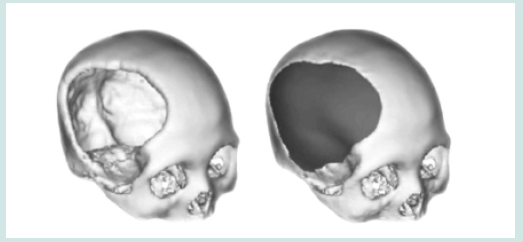
The procedure known as cranioplasty is used to address deformities in the skull. It is necessary to preserve the subsurface brain and precisely redress significant aesthetic defects [8]. Currently, anatomical data from scanning data from Computer Tomography (CT) can be used to create Three-Dimensional (3D) representations of anatomical structures. Further information for 3D modelling of both the hard and soft tissues of the human body structures include Magnetic Resonance Imaging (MRI), computer to-myography (CT), ultrasound, etc. Tangible models can be made from these 3D models (called bio-models) using Rapid Prototyping (RP). The design data types [8] based on medical image processing (bone contours, 3D Stereolithography STL solid models), as well as geometrical modelling techniques (wireframe, surface, and solid), are chosen for the design process depending on the manufacturing technologies used to produce implant bio-models. [4,8] The most common data source for 3D building of bone structures, CT scanning data, is utilized to begin the modelling process of cranioplasty implants. This data is then segmented into medical image processing software (for e.g., Materialize Mimics software) to separate the bone structure from the soft tissue. Figure 1 MIP (Medical Image Processing) [8] and RP (Rapid Prototype) software generate bone geometrical data as 3D solid models and scanning slice contours (typically IGES and STL solid). Figure 2 shows the procedure to get a skull implant RP. The procedure to get a skull implant RP involves the following steps (Figure 2):
Patient CT scan
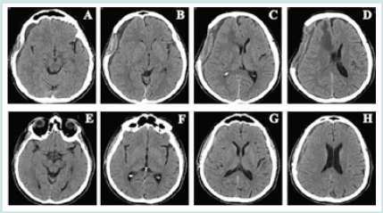
A CT (Computed Tomography) scan is a medical imaging procedure that uses X-rays and computer processing to create detailed 3D images of the skull [4,8]. These images are generated using a combination of X-rays and computer processing to create a 3D model of the skull. This model is made up of a series of "slices" that show cross-sectional views of the skull. These slices can be used to examine the skull in de-tail, including the shape and density of bones, the location of blood vessels and nerves, and the presence of any abnormalities or injuries. The CT scan data is typically stored in DICOM (Digital Imaging and Communications in Medicine) format. CT scans Figure 3 [21] are commonly used in medical diagnostics to diagnose a wide range of conditions, such as skull fractures, brain tumors, and bleeding in the brain. In the context of creating a skull implant RP, the CT scan data is used to create a 3D model of the patient's skull, which can be used to design and manufacture a custom-fit im-plant that closely matches the shape of the patient's skull.
Material MIMICS
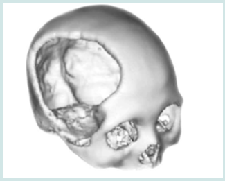
Material MIMICS is a specialized software program that is commonly used in medical imaging to process and analyze CT scan data [4,8]. This software is used to create a 3D model of the patient's skull and allow users to import, segment, and isolate specific structures or regions of interest from CT scan data. Once the region of interest is segmented, Material MIMICS can be used to create a 3D model of the structure or region. The software offers a wide range of tools and features to manipulate and customize the 3D model, such as smoothing, trimming, and merging. Material MIMICS is particularly useful for creating 3D models Figure 4 [8] of anatomical structures, such as the skull, be-cause it allows for accurate and detailed segmentation of the structure from the CT scan data. The resulting 3D model can then be used to design and manufacture custom im-plants or prosthetics that closely match the shape of the patient's anatomy. In summary, Material MIMICS is a powerful tool for creating 3D models of anatomical structures from medical imaging data, and it is widely used in the field of medical im-aging and device design.
Generation of A 3D Stereolithography Model
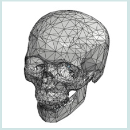
Once the region of interest is segmented using Material MIMICS, the next step is to create a 3D STL (Stereolithography) model from the segmented data. This involves ex-porting the segmented region as an STL file format, which is a widely used file format for 3D printing and rapid prototyping. An STL file is a triangulated mesh Figure 5 of the segmented region, where each triangle is defined by its vertices and the normal vector of the triangle. The number and size of the triangles in the mesh determine the level of detail and resolution of the resulting 3D model.
To generate an STL model from Material MIMICS, the user would typically follow these steps:
a. Import the CT scan data into Material MIMICS.
b. Use the segmentation tools in Material MIMICS to isolate and segment the region of interest (in this case, the skull).
c. Refine the segmentation to ensure that only the desired region is segmented and that any unwanted or extraneous data is removed.
d. Verify and check the segmentation to ensure that it is accurate and representative of the patient's anatomy.
e. Export the segmented region as an STL file format.
f. The software may offer options to control the mesh density, orientation, and resolution of the resulting STL file.
g. Save the STL file to a location on the computer.
The resulting STL file can then be imported into other software programs for further processing, such as a CAD program for the design and optimization of the implant or prosthesis. Alternatively, the STL file can be used directly for 3D printing or rapid pro-totyping of the implant or prosthesis.
In summary, generating an STL model from Material MIMICS involves careful segmen-tation of the CT scan data to isolate the region of interest, followed by exporting the segmented region as an STL file format with appropriate settings for the desired level of detail and resolution.
Slicing and NURBS generation in CAD
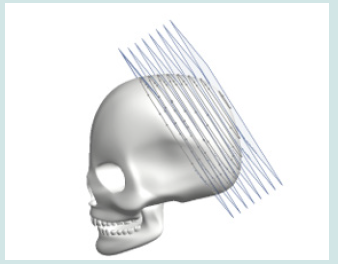
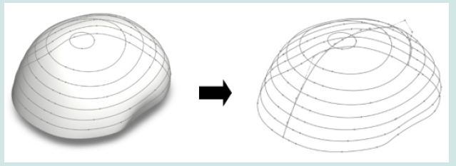
The STL file is imported into a CAD (Computer-Aided Design) software program for model optimization [3,6,7,10]. In the CAD program, the model can be further refined and optimized for the specific manufacturing process that will be used to create the final product. Slicing in CAD (Computer-Aided Design) involves taking a 3D model and "slicing" it into a series of 2D cross-sectional layers that can be used to guide the manufacturing process. The slicing process involves dividing the 3D model into a series of parallel planes, each representing a specific layer of the final product, typically 8 mm in thickness [9]. The number of layers is determined by the desired level of detail and resolution of the final product. The resulting 2D layers slicing an STL model in a CAD program will typically generate a 2D sketch at each intersection of the slicing plane and the surface of the model. These sketches represent the cross-sectional profile of the model at each layer. The CAD program will typically generate these sketches automatically, based on the position and orientation of the slicing plane. The sketches will include all the relevant geometry of the cross-sectional profile, such as curves, arcs, and lines. A guiding NURBS can be generated that intersects each profile at extreme points. These NURBS following with a control point can further be approximated in MATLAB to generate a higher order NURBS which will closely resemble the profile of the actual skull. In summary, slicing an STL model in a CAD program generates a 2D sketch at each in-tersection of the slicing plane Figure 6 and the surface of the model. Direct slicing of the skull model on a CAD platform generates 8 slices or planes at 8 mm ‘Z-distance’ The 2D images are converted into NURBS (Non-Uniform Rational B-Splines) curves [19,20]. NURBS curves are a mathematical representation of the shape of the skull, that acts like a guiding curve that decides the final shape of the implant Figure 7. They are defined by a set of control points that determine the shape of the curve. The NURBS curves are used to create a smooth and accurate surface that closely matches the shape of the skull. NURBS are extracted in the *.DXF format and thereafter transferred to MATLAB program for further approximation. These sketches represent the cross-sectional profile of the model at each layer. This is an important step in creating custom implants or prosthetics, as it allows for precise control over the manufacturing process and ensures that the final product closely matches the patient's anatomy.
Optimization Of Implant
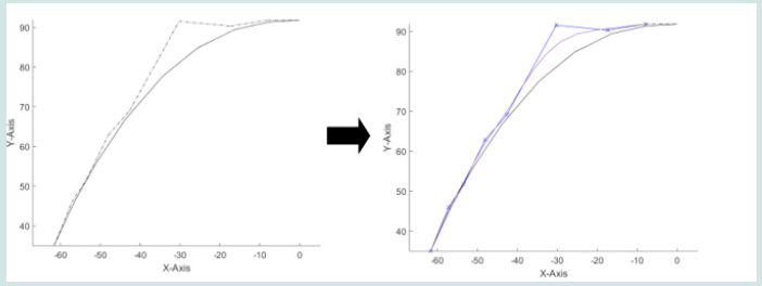
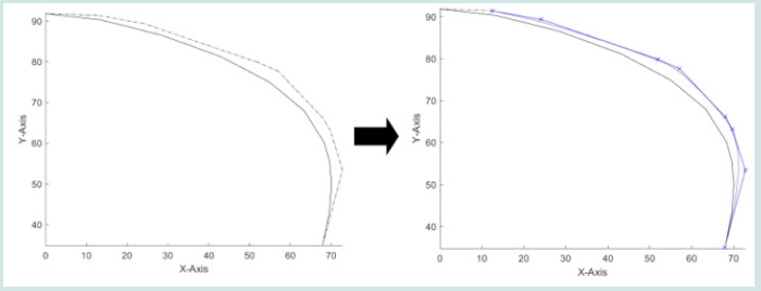
The process of optimizing NURBS curves using MATLAB is an important step in creating accurate and smooth NURBS surfaces for custom skull implants. NURBS curves are mathematical representations of curves and surfaces, consisting of control points and weights that define the shape and curvature of the surface. By optimizing these curves, it's possible to create higher-order curves that more accurately represent the shape of the skull, resulting in a more precise and accurate implant. in MATLAB, optimization of the NURBS curves typically involves adjusting the control points and weights to create a smoother and more accurate curve. This can be done using a variety of techniques, such as polynomial fitting, least squares optimization, or spline fitting. The goal is to create a curve that closely matches the original CT scan data, while also ensuring that it's smooth and free of any unwanted bumps or irregularities. Once the NURBS curves are generated, they may need to be optimized to improve their accuracy and smoothness [18]. MATLAB can be used to manipulate and optimize the NURBS curves to create higher-order NURBS Figures 8 & 9, they can be transferred back to the CAD software to create smooth NURBS surfaces for the skull implant. The use of MATLAB in this process allows for precise control over the shape and curvature of the final implant, ensuring a high degree of accuracy and precision. A NURB curve requires four elements: (1) a set of n+1, control points Pi (0≤i≤n), (2) a knot vector U of m+1 knots u_0≤u_1≤u_2…≤u_(m-1)≤u_m=1, (3) a degree p satisfying m=n+p+1, and (4) A NURBS curve adds a weight w_i≥0 to control point Pi . NURBS curve can be represented by the following equation:
It's worth noting that the optimization process can be time-consuming and may require a significant amount of computational power, particularly for complex shapes and curves. However, the use of advanced software tools such as MATLAB can greatly streamline this process and ensure that the final implant is as accurate and precise as possible.
NURBS Surface Generation
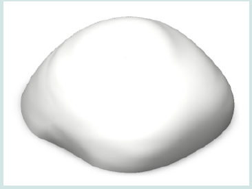
After the NURBS curves are optimized in MATLAB, the new curve data is transferred back to the 3D software program [18] for surface generation. The software uses the new NURBS curves to create NURBS surfaces Figure 10 that closely match the shape of the skull. The NURBS surfaces are generated by interpolating a network of NURBS curves. The surface is created by connecting the curves in a way that maintains continuity and smoothness. The software uses the control points and weights of the NURBS curves to determine the shape and curvature of the final surface. Once the NURBS surfaces are generated, approximations are performed to ensure that the surfaces are smooth and continuous. In the CAD program, the NURBS surfaces can be further refined and optimized as needed. The CAD software allows for the manipulation of the surfaces, including the addition or removal of control points, adjusting weights, and modifying the surface shape. The goal is to create a final NURBS surface that accurately represents the shape of the skull and is free of any irregularities or bumps. Once the NURBS surfaces are finalized, point cloud data is generated to create a mesh of the surface. The mesh is then used in the rapid prototyping process to create the final custom skull implant.
Point Cloud Data of Implant
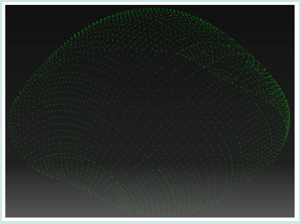
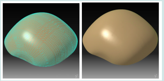
For further optimization and investigation, [5,6,9] NURBS surfaces generated in the previous step are used to create a point cloud that closely matches the implant and the shape of the skull. The point cloud data Figure 11 is then used to create a mesh, which is the final step in creating the skull implant RP. The mesh created may need to be further optimized to ensure that the implant fits perfectly into the patient's skull. This step may involve adjusting the shape or size of the implant, as well as adding or removing features to ensure a good fit [6]. The final mesh is then sent to a 3D printer or manu-facturing facility to produce the final skull implant RP. The point cloud data represents the surface of the skull implant with a high degree of accuracy and is used to create a mesh of the surface. The mesh Figure 12 is created by connecting the points in the point cloud data with a series of triangles. This process is known as triangulation. The mesh is a digital representation of the surface of the skull implant and is used in the rapid prototyping process to create the physical implant. In the rapid prototyping process, the mesh is used to create a physical model of the skull implant. This is typically done using a 3D printing or CNC milling machine. The machine uses the mesh data to create a physical model of the implant out of a biocompatible material such as titanium or medical-grade polymer. The final custom skull implant is then tested to ensure that it fits properly and meets the specific needs of the patient. The use of NURBS modeling and rapid prototyping allows for the creation of highly customized implants that closely match the shape of the patient's skull and provide the best possible fit and function.
Conclusions
In conclusion, the process of creating a custom skull implant using NURBS modeling and rapid prototyping involves several steps. The first step is to obtain a CT scan of the patient's skull, which is used to create a triangulated model of the skull using Material MIMICS software. The model is then sliced on a CAD platform to generate NURBS curves, which are optimized using MATLAB to create higher-order curves that more accurately represent the shape of the skull. The new NURBS curves are then transferred back to the 3D software program to generate NURBS surfaces that closely match the shape of the skull. Once the surfaces are finalized, point cloud data is generated to create a mesh of the surface, which is used in the rapid prototyping process to create the final custom skull implant. This process allows for the creation of highly customized implants that provide the best possible fit and function for the patient. It is a promising approach for the development of personalized medical devices and implants that can be tailored to meet the unique needs of individual patients. This process can eliminate the repetitive incision of the skull to get impressions for the casting process. However, further research is needed to optimize the process and make it more efficient and cost-effective.
References
- H Mao, Kwok TH, Chen Y, Wang CCL (2019) Adaptive slicing based on efficient profile analysis. Computer Aided Design 107: 89-101.
- Minnema J, van Eijnatten M, Kouw W, Diblen F, Mendrik A, et al. (2018) CT image segmentation of bone for medical additive manufacturing using a convolutional neural network. Computers in Biology and Medicine 103: 130-139.
- Minetto R, Volpato N, Stolfi J, Gregori RMMH, da Silva MVG MVG (2017) An optimal algorithm for 3D triangle mesh slicing. Computer Aided Design 92: 1-10.
- Skrzat J, Spulber A, Walocha J (2016) Three-dimensional model of the skull and the cranial bones reconstructed from CT scans designed for rapid prototyping process. Folia Med Cracov 56(2): 45-52.
- Vlachkova K, Terziev P (2012) A Comparison of Surface Subdivision Algorithms for Polygonal Meshes. AIP Conference Proceedings1487: 343-350.
- Ma W, But WC, He P (2004) NURBS-based adaptive slicing for efficient rapid prototyping Computer-Aided Design 36: 1309-1325
- Mohan Pandey P, Venkata Reddy N, Dhande SG (2003) Slicing procedures in layered manufacturing: a review. Rapid Prototyping Journal 9 (5): 274-288.
- Chi Hieu Le, Bohez E, Jos Vander Sloten, Phien HN, Vatcharaporn Esichaikul, et al. (2003) Design for medical rapid prototyping of cranioplasty implants. Rapid Prototyping Journal 9 (3): 175-186.
- Koc B, Lee YS (2002) Hollowing STL Objects with Biarcs Fitting to Improve Efficiency and Accuracy of Rapid Prototyping Processes.
- Dorman J, Rockwood A (2001) Surface design using hand motion with smoothing. Computer Aided Design 33(5): 389-402.
- Mani K, Kulkarni P, Dutta D (1999) Region-based adaptive slicing. Computer Aided Design (5): 317-333.
- Lan PT, Chou SY, Chen LL, Gemmill D (1997) Determining fabrication orientations for rapid prototyping with Stereolithography apparatus. Computer Aided Design 29(1): 53-62.
- Kulkarni P, Dutta D (1996) An accurate slicing procedure for layered manufacturing. Computer Aided Design 28(9): 683-697.
- Alciatore DG, Wohlers TT (1996) Importing and reshaping digitized data for use in rapid prototyping: a system for sculpting polygonal mesh surfaces. Rapid Prototyping Journal 2(1):13-23.
- Rajagopalan M, Aziz NM, Huey CO (1995) A model for interfacing geometric modeling data with rapid prototyping systems. Advances in Engineering Software 23 (2): 89-96.
- Jamieson R, Hacker H (1995) Direct slicing of CAD models for rapid prototyping. Rapid Prototyping Journal 1: 4-12.
- Peters J (1993) Smooth free-form surfaces over irregular meshes generalizing quadratic splines. Computer Aided Geometric Design 10(3): 347-361.
- Hsu WM, Hughes JF, Kaufman H (1992) Direct manipulation of free-form deformations. SIGGRAPH Comput Graph 26(2): 177-184.
- Doo D, Sabin M (1978) Behaviour of recursive division surfaces near extraordinary points. Computer Aided Design 10(6): 356-360.
- EE Catmull, J Clark (1978) Recursively generated B-spline surfaces on arbitrary topological meshes. Seminal graphics.
- Deng Z, Davis J (2020) Transient ischemic attack post craniectomy: A case report and review of sinking skin flap syndrome. Interdisciplinary Neurosurgery 20: 100640 .

Top Editors
-

Mark E Smith
Bio chemistry
University of Texas Medical Branch, USA -

Lawrence A Presley
Department of Criminal Justice
Liberty University, USA -

Thomas W Miller
Department of Psychiatry
University of Kentucky, USA -

Gjumrakch Aliev
Department of Medicine
Gally International Biomedical Research & Consulting LLC, USA -

Christopher Bryant
Department of Urbanisation and Agricultural
Montreal university, USA -

Robert William Frare
Oral & Maxillofacial Pathology
New York University, USA -

Rudolph Modesto Navari
Gastroenterology and Hepatology
University of Alabama, UK -

Andrew Hague
Department of Medicine
Universities of Bradford, UK -

George Gregory Buttigieg
Maltese College of Obstetrics and Gynaecology, Europe -

Chen-Hsiung Yeh
Oncology
Circulogene Theranostics, England -
.png)
Emilio Bucio-Carrillo
Radiation Chemistry
National University of Mexico, USA -
.jpg)
Casey J Grenier
Analytical Chemistry
Wentworth Institute of Technology, USA -
Hany Atalah
Minimally Invasive Surgery
Mercer University school of Medicine, USA -

Abu-Hussein Muhamad
Pediatric Dentistry
University of Athens , Greece

The annual scholar awards from Lupine Publishers honor a selected number Read More...


