


Lupine Publishers Group
Lupine Publishers
ISSN: 2643-6736
Research Article(ISSN: 2643-6736) 
Design Optimization of a Novel Curvilinear-Jaw Robotic Gripper Volume 3 - Issue 3
Received:November 17, 2021 Published: December 2, 2021
Corresponding author: Debanik Roy, Division of Remote Handling & Robotics, Bhabha Atomic Research Centre & Homi Bhabha National Institute, Department of Atomic Energy, Mumbai, India
DOI: 10.32474/ARME.2021.03.000162
Abstract
Robotic grippers, with several design variations in its jaws, are gaining popularity in commercial market worldwide in recent past. In fact, these customized robotic grippers are widely used for diverse end-applications in various arenas. We have aimed to optimize the mechanical design of such customized robotic grippers having two fingers (jaws), as those grippers are the most prevalent variants in industrial robots. In this study, a niche contigutive robotic gripper is developed for direct adhesion contact, in order to meet the technical challenges of force-closure of grasp. The prime focus of our research is reduction of the tare-weight of the prototype gripper keeping its strength unaltered under the threshold of grasping maximum payload. Through Finite Element Analysis and optimization thereof, material retention percentage is defined for the prototype gripper so as to improve its overall envelope.
Keywords: Topology; Optimization; Finite Element Analysis; Design; Robotic Gripper; Articulated Jaw
Introduction
Design modulation and customization of robotic grippers are
gaining popularity in global perspective due to its effectiveness in
a variety of end-applications. However, in many of the new designs
prototyping poses considerable challenge because of the external
envelope of the gripper and its self-weight. The objective of the
present research is to reduce the tare-weight of a novel curvilinearjaw
robotic gripper keeping the strength unaffected by imbibing
topology optimization niche. In fact, any new engineering component
/ system will be rather bulky until the optimization is performed
on that entity. More weight means additional cost of manufacturing
for no motive. Although strong and light-weight design of a robotic
sub-system in static condition can be satisfactorily obtained by
optimization practices, designing an optimal robotic component
under real-time dynamic condition requires a different approach.
Topology optimization method permits users to attain ensemble
specifications of robotic systems where supports and loads are
positioned a-priori. Under such a situation, designer can pin-point
the best shape / contour of the very robotic component. This
absolute design freedom makes topology optimization a powerful
design tool in many areas, including robotic systems.
Enhancing features of parts through topology optimization,
deprived of applying manufacturing constraints, results in
organic design. This is because the material will self-define the
through-path from the load to the restraint, ensuring the most
effective shape mathematically. The present study describes the
syntax of the customized topology optimization routine as well
as use of optimization module of commercially available Finite
Element Analysis (FEA) software, with specific reference to the
prototype design of the robotic jaw gripper. The solver optimizes
for maximum stiffness, deformation, Eigen frequencies and many
other parameters. This has been accomplished by defining a design
space from which the solver can eradicate material until the most
optimal shape is realized. In order to attain the prime objective
of weight attenuation, static analysis of the prototype gripper is
performed using Finite Element Method (FEM) and based on the
simulation result and interpretation thereof, optimization region is
summarized. As explained earlier, FEA aids in designing durable,
lightweight components for the prototype robotic gripper and
optimization have been used to improve the design of the same
that is poised to be deployed in various real-time applications. The
analysis also allows users to specify where supports and loads are
acting in 3D space of the envelope of the gripper and permits the
software to find the finest profile. This helps in reducing the cost of
manufacturing by designing a real-life lightweight robotic gripper
for specified application. The overall external dimensions of our prototype gripper are 145 mm x 54 mm x 42 mm, which signals the
small-scale of the envelope that we are dealing with. The designed
gripper has a payload capacity of 1.4 kg (approx.) and being a
contigutive type of gripper, it can pick up objects that are cylindrical
and spherical in nature more effectively. In fact, the two important
aspects of robotic grasp, namely, ‘form closure’ and ‘force closure’
have been implemented in the customized design of the jaws of our
gripper. Since we have added complementary design metrics of
contiguity, the ‘form closure’ of the final grasp has attained superior
realization.
Manufacturing of the prototype gripper was very delicate
due to its inherent subtleness of the design, post its optimization.
Several iterations underwent to search out the best method of
manufacturing using precise & high accuracy machine-tools,
ensemble effort of which could make it possible to achieve the final
‘quality’ product. For example, laser techniques were invoked to
cut the thin parts and Computer Numerical Control (CNC)-based
machine tools were used for machining the rest of the mechanical
assembly of the prototype gripper. The methodology of topology
optimization has been instrumental in fine-tuning the design of
mechanical assemblies and structures including robotic systems
over the past decade. Although several researchers have attempted
to use this methodology for design orchestration, several gap areas
do exist, especially for small- enveloped assemblies and systems
that call for real-time dynamics in end-use. As part of fundamental
research, topology optimization of continuous linear elastic twodimensional
structures was attempted using optimality criteria,
wherein material was also selected as 2-D [1]. Fracture-free stability
of the final structure was ensured through structural nodal analysis
under plane state of stress in this work. The incorporation of FEA in
topology optimization problem has led to use of parametric design
variables in order to achieve the objective function [2]. The optimum
values of the design parameters were computed therein using
topology algorithm. On the other hand, one of the most popular
models of multi-objective genetic algorithm, namely, Constructive
Solid Geometry-based Topology Optimization Method (CSG-TOM)
was used for 2D topology optimization of compliant mechanisms
and was extended for 3D cases as well [3]. The primary enthusiasm
of the proposed approach was to develop and improve CSG-TOM
to include different test problems that could be handled by the
present popular techniques of topology optimization.
With the advent of various analytical approaches for topology
optimization, researchers have concentrated on component-level
optimization modules also. Tamta & Saxena [4] carried out the
topology optimization work on three design-models, viz. i] hook, ii]
corbel and iii] electric mast, by adopting customized program. It was
reported that the optimality criteria approach used in this research
converged very fast in comparison to other topology optimization
methods. Similar to the previous work, four types of brackets were
topologically optimized for loading conditions, assuming plane
state of stress in each bracket [5]. The optimal shapes (in form of
optimal distribution of material) of those brackets were determined
for given loads and boundary conditions. The optimality criterion
of volume reduction was found effective in this study because the
initial rectangular structured design space was converged finally
to truss like structure. Chapman [6] described optimization of
beam & cantilevered cross-section as well as plate topologies, by
augmenting new methods for the efficient use of FEA in a genetic
algorithm-based search. In fact, he proved that the motivation
for using genetic algorithm to perform structural topology
optimization is not an enhanced ability to find exact optima or an
increase in computational speed, but advancement in simplicity
and generality. The results for the topology optimization of beam
structures, performed by the ANSYS® - based optimality criterion,
were validated by Solid Isotropic Material with Penalization (SIMP)
method [7]. SIMP is a novel scheme based on penalty calculation
that was benchmarked with Bi-directional Evolutionary Structural
Optimization (BESO) method in the treatise. As part of the systemlevel
optimization, step by step procedure to use the optimization
tool for weight optimization of a front suspension upper control
arm of commercial heavy truck was reported by Anand & Misra
[8]. Another such study was conducted on a rear lower control arm
component where the structural requirement on that component
involves pre-tension, plastic hardening material behavior and
fatigue problems that were treated during the optimization process
[9]. Author has shown that by including peak loads from the chassis
rig cycle (robustness check) to the topology optimization task, it is
possible to improve fatigue life, besides reduction of effective stress.
Topology optimization of real-life systems often go with
multiple objective functions. A multi-objective optimization
approach was introduced by Kim [10], towards designing a special
gripper for a wearable robot. A six-bar linkage incorporating a
toggle mechanism was employed to reduce the overall weight of
the gripper while maximizing the gripping force. An optimum
design was selected from the Pareto front, which satisfies the
requirements of both coupler path and drive torque. Likewise,
multi-objective evolutionary algorithm was used to solve modified
bi-objective problem and to optimally find the dimensions of links
and joint angle of a robot gripper [11]. The study was extended to
find suitable relationships between the decision variables therein
and the objective functions. A force-voltage relationship could be
obtained from each of the non-dominated solutions which helped to
determine the voltage to be applied for the actuation of the gripper
based on the application. An optimal design procedure was used
to synthesize an adaptive monolithic compliant two-finger robotic
gripper with high mechanical advantage for grasping irregular
objects [12]. The study addressed novel numerical methods to
synthesize compliant mechanisms (made up of silicon rubber)
with higher output force. Liu [13] developed a void replacement
method to provide a smooth boundary representation of a topology
optimized design by eliminating sharp corners (i.e., replacement of
internal voids). A sensitivity-based location optimization method
was developed in this work to minimize stress concentration
around multiple voids by relocating the voids.
A novel process for modeling robot grippers and optimizing
their structure was reported, wherein equivalent Jacobian matrix
was derived to find the kinematic model while the dynamic model
was obtained using Lagrange formulation [14]. Based on these models, a structural multi-objective optimization (MOO) problem
was formalized in the static configuration of the gripper. We have
found that the design problem of two-finger grippers has been
approached and formulated as an optimization problem by using
the basic characteristics of grasping mechanisms [15]. A specific
case of study has been reported in this treatise, by using 8R2P
linkages1 as a proposed grasping mechanism. The intricacy of
topology optimization of robotic gripper system goes deeper as
and when we come across grippers with complex kinematics under
full payload semantics, such as: grippers with large re-orientations
(more than 𝞹/2 radian) [16]; industrially-used grippers with wide-spanned payloads in production-line [17]; miniaturized
small-payload multi-linked gripper for flexible robotic systems
[18] ; mechanics of grasping and finger-object contact interactions
pertinent to grasp analysis, simulation and synthesis [19] and FEsoftware
– based static & dynamic analysis of robotic gripper [20].
The advantages of deploying universal robotic gripper for productoriented
manufacturing applications were delineated by Reddy
[21].
Over the years, FEA has established its effectiveness in
complementing topology optimization of various robotic systems,
especially critical components like gripper and/or end-effector.
The design and analysis of a research testbed to study the control
of a two-link three-joint manipulator-coupled spacecraft with
independent attitude control systems was reported [22]. The study
incorporated free body diagrams to ensure proper load paths in the
ANSYS® models and FEA results were verified by the development
of the Lagrangian Equations of motion. Multi-objective optimization
was introduced for both path and torque requirements of a novel
toggle mechanism-driven robotic gripper, fitted atop a six-bar
planar linkage mechanism [23]. The drive torque was minimized
in this optimization model to achieve better grip safety and drive
efficiency. Nguyen and Phan [24] presented a novel design concept
of a compliant constant-force gripper mechanism (CFGM) that
can man oeuvre objects of various sizes. The design methodology
of this gripper used genetic algorithm-based shape optimization,
backed up by FEA to characterize the constant-force behavior
of the gripper under static loading. Computational analysis was
conducted for the design optimization of a planar 2-degrees-offreedom
(d.o.f.) modular flexure-based manipulator [25]. Haptic
control scheme was demonstrated to accurately track user motions
and guide task performance by utilizing the 2-d.o.f. experimental
platform. Chouhan and Kanwal [26] presented the procedure of
design and fabrication of a stepper motor controlled robotic gripper
to be used in industries for handling small objects. The study was
focused on detailed kinematic analysis in order to predict the design
parameters accurately that were useful in proper selection of motor
and linear actuator. It may be noted that although a significant share
of the past research has been aimed at topology optimization of
design parameters of finite-sized robotic gripper systems aided by
FEA, not much work has been reported for miniaturized grippers.
With miniaturization of the hardware, topology optimization too
needs orientation. In all practical cases, iterative process becomes
the rule-base for such optimization modules. In our work, we have
focused on three aspects of topology optimization, viz, design
iteration, load balancing and harnessing of system compliance.
In fact, these three paradigms remained hitherto as major open
problems in the domain of topology optimization of size-restricted
robotic gripper systems.
The paper is composed in six sections. The next section
describes the structural optimization of the prototype gripper by
highlighting its mechanical design, along with the optimization
technique involved in the study. Section 3 deals with the details
of the finite element modelling of the prototype gripper and defeaturing
of CAD assembly before proceeding for the final analysis.
Section 4 reports on the modal analysis of the prototype gripper via
FE-simulation, incorporating free-free vibration results and fixedfree
vibration results, prior to the initiation of optimization routine.
Section 5 discusses the static analysis of the prototype gripper via
FE- simulation. The mathematical modeling and allied parlances of
the customized topology optimization module has been delineated
in section 6, linking the results of static analysis to the optimization
module. Finally, section 7 concludes the paper.
Structural Optimization of The Prototype Robotic Gripper: An Overview
Structural optimization of any mechanical system is categorized
into three facets, viz
a) shape optimization
b) topology optimization
c) size optimization
However, out of these three sub-sets, the most universal
structural optimization method is topology optimization. This
method is useful in unearthing an optimal distribution envelope
of the material within a specified design domain without making
any assumptions a-priori about the geometry and shape of the
final design. The structural optimization problem of our robotic
gripper system is framed as an ‘objective function’, interlinked
with various design and state variables. The objective function (f)
signifies a global objective that may be maximized or minimized.
To cite a generic example from a mechanical system, stiffness of a
particular ‘structure’ can be an objective function, wherein design
of the structure, i.e., geometry defines the design variable{x} and
the state variables (y) are represented by the structural response.
It is crucial to identify the set of design variable as well as state
variables of a generic mechanical system prior to optimization, as
per the requirement of end-application. Accordingly, we too carried
out this exercise for the demarcation of {x} and (y) pertaining to the
domain of real-life use of the prototype robotic gripper.
It may be stated here that irrespective of the categories of
optimization, the generic rule-base of it becomes universal and
the principles are applicable to almost all sorts of real-time
mechanical systems. Thus, in our case of robotic gripper, the design optimization routine does follow symbiosis of ‘state variables’
and ‘state constraints’. Mathematically, the lemma of structural
optimization is based on the evaluation of the ‘objective function’ of
the proposed design of the robotic gripper. The ‘objective function’
being multi-dimensional, we need to adhere to minimization
attribute for getting the ‘topology optimized’ design values of
the prototype robotic gripper. The analytical expression for the
topology optimization is shown in eqn. (1) below.
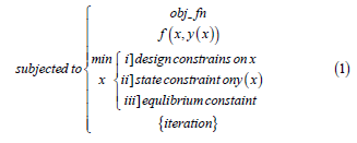
Equation 1 reveals two important aspects of topology
optimization process, namely: a] minimization of ‘design variables’
{x} and b] finite number of iterations that will be permitted.
Fundamentally, the process of minimization of objective function
(‘obj_fn’) is dependent upon the success of both of these two
indices. Now, the aspect of minimization of design variables is
branched into three domains, which are predominant in case of
the prototype gripper system. The first and foremost among these
domains is various design constraints on the design variable(s)
of the robotic gripper system, such as tare weight of the gripper
and its external envelope. The second aspect is state constraints
on the state variable(s), ‘y(x’) of the gripper system. This factor is
instrumental in defining the boundary conditions for the structural
and /or modal analysis of the robotic gripper system. This factor
also accounts for the external stimulants, e.g., payload of the gripper
or mounting pre-torque for the robotic assembly in the workplace.
The third factor, namely, ‘equilibrium constraint’ deals with the
intrinsic properties of the robotic gripper unit, such as material
parameters and system compliance.
Topology optimization of mechanical systems is
computationally expensive and a successful optimization routine,
by and large, pre-defines the total number of design iterations that
are permissible. In case of robotic systems, permissible number of
iterations gets piggy-backed with another critical paradigm, which
is manufacturability. In our case, the prototype robotic gripper
is poised to get constrained by the issue of manufacturability of
certain small-sized components that overrules design optimization.
Hence, number of iterations does play a significant role in the
structural optimization of the prototype robotic gripper. We will
get a clearer dimension for the usefulness of the iteration number
in the subsequent portions of this section, dealing with the aspects
of mechanical design of the prototype gripper system.
The ensemble of topology optimization, especially its iterations,
largely depends upon the intrinsic features and complexity of
manufacturing. Thus, it is important to scrutinize the spatial view
of the prototype curvilinear-jaw robotic gripper to get an idea
about the level of complexity (i.e., design & set variables) and extent
of optimization (i.e., iteration number). Figure 1 illustrates the 3D
isometric Computer Aided Design (CAD) view of our prototype
robotic gripper with its major constituent components indexed.
As illustrated in Figure 1, the ensemble topology of the prototype
gripper is comprised of 11 heterogeneous structural elements.
The extent of optimization will ensure design variations of each of
these 11 structural elements. The maiden element that plays role in
topology optimization is Jaw base [1], which is basically a fixation
point of the gripper to the robotic arm. The gripper is held fixed at a
pre-assigned location with respect to its own co-ordinate frame by
virtue of four fixation bolts, at desired locations (symmetric) [12].
The linear brass bushing [2] provides movement of the internal gear
module [3] with minimum friction. The internal gear module [3] is
designed to mesh with the mating hardened gears [4]. The motion
to the jaws [8] is being transferred by the external gear module
[5], as driven by the servomotor assembly [7]. The alignment of
the jaws is maintained with the help of bearings [11], which are
fitted in the upper plate [10]. The motor face is bolted to the lower
plate [6] with the help of screws. One of the crucial members of this
gripper assembly is the jaw-fixing bolt [9], which is used to fix four
components together, viz [4-10].
Figure 1: 3D Isometric View of the Prototype Curvilinear-Jaw Robotic Gripper.

Let us focus now on the actual implementation protocol of the
topology optimization that has been invoked in the present work.
The optimization technique, customized for the prototype robotic
gripper, involves importing the CAD model in the compatible
format and performing the finite element analysis as well as
some de- featuring of unwanted features. Both static and dynamic
analysis need to be performed in order to visualize the results and
defining the optimization regions. After interpreting the results
so obtained, the objective function and constraints are defined,
as required for the real-time run of the robotic gripper system.
The core routine of topology optimization is performed then
after. Once the topology optimization code (customized software)
provides the optimized model after completing the finite number
of iterations, the stress analysis and modal analysis are performed
again. The final design model of the prototype robotic gripper is
said to be ready if satisfactory results are accomplished at the
termination of the optimization iterations. Else, the model has to
be re-optimized to meet the required objectives. The overall flow
chart of the topology optimization routine used in the present
study is presented in Figure 2. As evident from the flow chart, the
customized optimization routine that has been implemented for
the prototype robotic gripper is propped by two functional units,
namely: a] CAD Model & b] Finite Element Model. At the beginning,
these two models start functioning independently till the first level
of optimization is achieved. Thus, through “CAD Model” route, we
undertake FEA directly by importing the CAD model and various
analyses are performed. Results of those analyses (in the form of
stress, deformation & mode shapes) are stored for direct input to
the optimization routine. It may be noted here that CAD Modelroute
is fool-proofed for shape & size optimization as major inputs
of CAD are related to the features linked with ensemble shape &
size of the prototype gripper. Let us now take a look at the “Finite
Element Model” route, which has an in-built optimization module.
We can achieve an interim optimized design of the gripper system
through this route after performing basic analysis & fixing up the
boundary constraints for the FEA. Our customized “Optimization”
module (refer to the block at the middle: Figure 2 accepts multiple
iterations in two pathways. The first pathway is the output of the
CAD-driven FEA while the second one is the outcome of the static &
modal analysis. The optimized design, as obtained from the “Finite
Element Model” route, is checked for the ‘accomplishment’ that
may lead to the generation of the final design.
It may be stated that the flow chart of Figure 2 is essentially
generic, and our topology optimization routine is equipped to
handle design optimization of other robotic assemblies too. The
fundamentals of the routine and lemma will remain unaltered,
although the coding has been customized for our robotic gripper
system.
Figure 2: The Overall Flow Chart of the Topology Optimization Used.

Finite Element Modeling of the Prototype Gripper
The finite element modeling of the prototype robotic gripper and subsequently, analysis is carried out using commercial finite element (FE) software. At the outset, the modelling is done in commercial CAD software. The CAD model is imported (to the FE platform) in. step format, which is a universal format, and any commercial FE software has an inbuilt option to process the same. We have used FE-Pre-processor for cleaning the unwanted features in the CAD assemblage and executed ‘de-featuring’ function seamlessly. Figures 3a,3b illustrate the original CAD model of the prototype gripper, while the first level ‘de-featured’ version of the same is presented in Figures 4a,4b. The isometric view of the gripper with its functional assemblies is shown in Figure 3a and its backbone topology view is presented in Figure 3b. In contrast to the original CAD model, first- level de-featured version of the isometric view of the prototype gripper is presented in Figure 4a, wherein the servomotor assembly is trimmed off. The subsequent topology optimization routine will incorporate a ‘remote forcing function’ in lieu of the physical servomotor that will act through the center of gravity of the servomotor. Likewise, small holes & fillets are abandoned from the backbone topology of the prototype gripper at the end of first-level de-featuring (refer Figure 4b). This sort of selective trimming of non-fundamental geometric features is an interesting paradigm of topology optimization.
Figure 3a: Original CAD Model of the Prototype Gripper: Isometric View (with functional assemblies).

Figure 3b: Original CAD Model of the Prototype Gripper: Backbone Topology View.
Index: A: Backbone Assembly; B: Gear Assembly; C: Jaw Assembly; D: Fixing Bolt Assembly; E: Servomotor Assembly; F:
Small Holes; G: Fillets; H: Gear Mounting.

Figure 4a: First Level De-Featured Version of the Prototype Gripper: Isometric View.

Figure 4b: First Level De-Featured Version of the Prototype Gripper: Backbone Topology View.

It may be noted here that since minor features in the CAD like pinholes, fillets, chamfers, screws and bearings can affect the mesh quality for the FEA, we need to take a call on the enhancement of the computational time. Thus, the extent of ‘de-featuring’ will be crucial in taking the final judgement for FEA as the results will be highly affected by the accuracy of the ‘de-featuring’. Since all the parts in the ‘de-featured’ CAD assemblage of the prototype gripper are solids with considerable dimensions, 3D elements are used for the FEA. Hexahedral elements are the best choice to be used in 3D domain because of its accuracy but complex shapes cannot always be meshed using hex-elements. A combination of higher-order tetrahedral and hexahedral elements is used in the FE-model, as complex geometries cannot be meshed with perfect cubes. Figure 5a shows the ensemble finite element model of the prototype gripper. Figure 5b shows the portion of the FE- modelled gripper having tetrahedral elements only, while the part-assembly of the FE- modelled mesh using combined tetra and hexahedral elements is illustrated in Figure 5c. However, it may be noted that hex dominant method has been used in the meshing of the portion of the gripper assembly of Figure 5c.
Figure 5a: Finite Element Model of the Prototype Gripper: Ensemble Model.

Figure 5b: Finite Element Model of the Prototype Gripper: Zones with Hexahedral Elements.

Figure 5c: Finite Element Model of the Prototype Gripper: Zones with Combined Hexahedral and Tetrahedral Elements.

Higher order hexahedral element is defined by 20 nodes having
3 degrees- of-freedom (DOF) in translatory motion per node, viz.
{Tx, Ty, Tz} and higher order tetrahedral element is defined by 10
nodes having 3 DOF in translatory motion per node, viz. {Tx, Ty,
Tz}. The hexahedral elements are preferred in FE-model in those
specific regions where the model is not complex. The tetrahedral
on the other hand is preferred in regions where the model is
complex. As evident from the CAD model of the prototype gripper
shown in Figure 1, the upper plate and jaw base are not as complex
as internal and external gears. Hence, we have judiciously used
hexahedral, tetrahedral and combination of these two elements as
per the requirement, which has culminated in not only improvised
FEA of the entire gripper system but also helped in reducing the
number of elements count in the model. The element size is chosen
based on the minimum length of the geometric feature in the
model, i.e., the gripper assembly. Mesh density is one of the very
important parameters in obtaining acceptable results since the
algorithm cannot alter the nodal locations. Since the optimization
results will be based on the efficiency of removal of elements so
finer mesh is expected in the iterations of the analysis. The node
and element count of the pre-optimized FE-model are shown in
Table 1. The final revised CAD of the prototype gripper (post-defeaturing)
is shown in Figure 6, along with the location for fixation
of the driving servomotor. The next step of our FEA is to define the
loads and boundary conditions. The load and boundary conditions
are applied to the gripper model as shown in Figures 7a & 7b and
tabulated in Table 2.
Since, the geometric modelling and material properties for
the FEA are assigned in ‘N’ and ‘mm’, accordingly, we need to
convert torque and forces in ‘N-mm’ and ‘N’ respectively. We have
considered the total maximum payload that needs to be grasped
by the prototype gripper is 1.4 kg. Thus, a remote point is created
in the FE- software at the center of the jaws. The remote force
of 14 N (1.4x9.8066=>14N) is then applied. The servomotor,
responsible for the overall actuation of the gripper system, needs
to supply continuous torque of 4.8 Nm to the gears. Hence, total
torque of 4800 Nmm is applied at the gear location at the fitment
of the servomotor. We have carried out the pre-processing of the
FEA (node selection, meshing, loading & boundary condition) of
the prototype robotic gripper system in subtle detail, as explained
above. Once the pre-processing is done the FE-model is submitted
to the FE-solver. Direct solver is used in our application, wherein
equivalent stress and the total deformation are evaluated. In order to keep the tare weight of the gripper minimum, majority of the
components are proposed to be manufactured using aluminium.
One of the sliding parts in the model is proposed to be made up
of brass in order to keep the friction minimum. The gears are
proposed to be made up of hardened steel with hardness up to 55
HRC. Various engineering properties of the materials used in the
manufacturing of the prototype robotic gripper are shown in Table
3.
Table 1: Mesh Statistics of the FE-Models of the Prototype Gripper System.

Table 2: Loading and Boundary Conditions of the FEA of the Gripper System.

Table 3: Engineering Properties of the Materials Used in the Manufacturing of the Gripper.

Figure 6: Post -de-featured CAD Model of the Prototype Gripper.

Figure 7a: Applied Loads and Boundary Conditions of FE-Model of the Prototype Gripper: in Isometric View.

Figure 7b: Applied Loads and Boundary Conditions of FE-Model of the Prototype Gripper: inside View.

Modal Analysis of the Prototype Robotic Gripper Via Finite Element Analysis –Based Simulation
Paradigms of Modal Analysis
In a typical modal analysis, single or multiple natural frequencies of vibration can be evaluated based on the requirement of the endapplication. The numerical values of such modal frequencies can be plotted suitably and interpreted for various physical parameters pertaining to the system. With this backdrop, the modal analysis of the robotic gripper system under study was carried out with the underlying objective of minimization of the volume and mass of the gripper system. To begin with, we have selected the ‘rigid body mode’ of analysis that is demarcated as the free translation or rotation of a body deprived of enduring any substantial internal deformation. As part of this analysis, there will be six rigid body modes, namely, three translational (TX, TY, TZ) and three rotational (RX, RY, RZ). For a free- free normal modes analysis, we have assumed that there are no loads or restraints over the gripper body. In other words, the gripper body will not undergo any internal deformation but will be able to move or rotate without restrictions. This free-free run also ensures that there are no appreciable modelling errors in the assembly. If any component in an ensemble (muster) is not relatively associated with the other or if any contact between the two mating members is not defined or some zonal meshes are not compatible, we will get some non-zero frequencies within first six frequency results in the analysis. After the free-free run, the next step is to perform the fixed - free run. The boundary conditions are then added, and fixed-free analysis is done on the structure, i.e., the gripper-body. Number of modes to be extracted depends upon the percentage ratio of effective modal mass to total mass of the gripper system.
Results Obtained
As per the FEA, we have found that the natural frequency of the prototype gripper system is very high, above 1000Hz. This shows that there is no need to go for further dynamic analysis as no resonance will occur and the gripper-body is fully rigid. Thus, only static simulation and its optimization are useful. Hence, we have carried out FE-simulation for the first two mode shapes only (at two different working planes) that are illustrated below. We have used two commercially available FE-platforms to carry out the modal analysis, namely, ANSYS® and FEAST® software2. While FEA using ANSYS® does have the leverage of detailed CAD as the backbone, the FE-modeling in FEAST® is a slight deviation, so far as the external geometry of our prototype gripper is concerned. The gripper system has been modelled as a cantilever beam, having two different cross-sections. We have used these two unequal cross-sections, respectively for the gripper-body and gripper-jaws, in order to facilitate 1D simulation and run the one-dimensional problem. Figure 8 illustrates the cantilever beam modelling of the gripper in FEAST®. It is to be noted that it is not possible to determine the exact cross-section of the cantilever beam, as the modeling of Figure 8 is merely an approximation that is felt sufficient for the FEA under FEAST®. With reference to parts ‘A’ & ‘C’ of Figure 3a, we have arrived at the thickness of the backbone assembly and jaw assembly of the gripper as 38 mm. and 21 mm respectively. As illustrated in Figure 8, the ensemble 1D model is composed of two contigutive planar beams, the larger one symbolizes ‘Gripper-Body’ (65 mm x 38 mm.) while the smaller beam represents ‘Gripper- Jaws’ (80 mm x 21 mm.). We have used these two different crosssections judiciously, in order to run the 1D problem effectively in FEAST®. It may be noted that as per the above layout as well as the overall external dimension of the gripper, the gripper-jaws are modelled using a rectangular cross-section of 54 mm x 21 mm and the gripper-body is modelled by another rectangular cross-section of 42 mm x 38 mm for the FEA using FEAST®. Figures 9a,10a show the mode shape results using ANSYS® code and Figures 9b,10b show the mode shapes plotted in FEAST® software. It may be noted here that although both these FEA-software do perform the requisite modal analysis with sufficient accuracy, the modeling approach is different. We have incorporated the results of both ANSYS® as well as FEAST® software in order to get better insight to the vibration characteristics of the prototype gripper, besides comparison of the numerical values. As per the modeling in FEAST® software (refer Figure 8) and subsequent simulation, mode shapes can be simply pictured as deflections of a continuum cantilever beam, using 1-D results. This is, no doubt, a unique characterization and quite effective in our case. The cantilever-beam approximation is invoked because the gripper model is fixed at the end and free at the other, so a generalized free body diagram can be represented by a line-body and its mode shape can be idealized by the mode shapes of this line-body. This representation of a line-body along with its mode shapes can easily be compared with the 3D model to check whether the mode shapes are correct as per the fundamentals of vibration. The ‘beam’ is essentially demonstrated using 3D beam elements of arbitrary length, material properties and cross-section, since only the mode shapes are of interest and not the frequencies. The frequencies will never match with the results of 1D as the geometric shape cannot be realized in 1D.
Figure 8: Cantilever Beam Modeling of the Prototype Gripper using FEAST® software.

Figures 9a,9b,10a & 10b show the analogous mode behavior of 3D model of the prototype gripper and its 1D simplification, respectively using ANSYS® and FEAST®. The colour contour shows the variation of mode shapes results in form of deflection hue, while the horizontal span of the FEA remains same, i.e., 145 mm. (total length of the prototype gripper). The red colour shows the maximum magnitude of mode which is the modal displacement. Figure 9a shows the deflection of gripper in the X-Y plane (first mode shape), as per FEA result from ANSYS® (maximum deflection at jaw-tip: 154.99 mm). At resonant condition this deflection may increase in the amplitude and can damage the components in the surrounding area. Figure 10a shows the mode shape results in X-Z plane (second mode shape), as per analysis in ANSYS®. Similar screenshots for these two mode shapes under FEAST® are shown in Figures 9b,10b. Thus, this mode can affect the adjacent components in contact. Since the frequencies at these two mode shapes are high enough, there is no need to work out on the modal frequency further as those will never occur. As the paradigms of FE- modeling are not identical in these two FE-software, we have got different values of the modal frequencies for the prototype gripper. While in ANSYS®, the frequencies are 1302.4 Hz. (Mode # 1) & 2084.6 Hz. (Mode # 2), the corresponding values in FEAST® are 1487.34 Hz. (Mode # 1) & 1855.83 Hz. (Mode # 2).
Figure 9a: FE-screenshots of the First Mode Shape of the Prototype Gripper: ANSYS®.

Figure 9b: FE-screenshots of the First Mode Shape of the Prototype Gripper: FEAST® Software.

Figure 10a: FE-screenshots of the Second Mode Shape of the Prototype Gripper: ANSYS®.

Figure 10b: FE-screenshots of the Second Mode Shape of the Prototype Gripper: FEAST® Software.

It is important to note here that the modal frequency of the prototype gripper has been found higher in X-Z plane in both ANSYS® as well as in FEAST®, in comparison to that in X-Y plane. We have used this finding as a critical input for the topology optimization thereof. The crux of the FE-simulation for the modal analysis is linked with defining the contact geometries between various mating parts of the prototype robotic gripper. The success of the modal analysis depends on the very aspect of contact kinematics. As modal analysis of the prototype robotic gripper is primarily aimed at its real- time dynamics, it is crucial to model the gripper system with details of the contact kinematics. ANSYS® provides good options to define contact between the constituent and contiguous parts of the prototype gripper under FE-modeling. However, contact body and target body needs to be defined adequately for establishing contact kinematics in ANSYS®. This paradigm is at times, becomes tricky, especially for small-sized envelopes like our gripper system. We have overcome this difficulty in modeling by using some advanced features of ANSYS® towards defining the contact, which is geometrically equivalent to ‘bond contact’. Nonetheless, we could not avoid a small amount of ‘gap’ in the FE-model despite proper definition of the contact. This inherent shortcoming of FE-modeling (mesh generation phase) gets alleviated in the analysis phase. The FEA of the prototype robotic gripper using ANSYS® provided us with several useful options to detect this ‘gap’ (of FE-mesh in bond contact) such as pinball radius. The FE-program of ANSYS® considers the closure of the bond contact region within the userdefined pinball radius. In other words, the contact and target pairs need to be fully inside this pinball region. In contrary, the modal analysis of the prototype gripper under FEAST® relies largely on the structural syntax of the ensemble. Thus, FEAST is more assertive to rigid body contact kinematics and a bit poor in identification of the ‘gaps’ of the FE-mesh. At times, this restricts the FE-simulation of modal analysis using FEAST for systems with semi-compliant interconnected members, such as our gripper system.
Static Analysis of The Prototype Robotic Gripper
Methodology and Paradigms
The static analysis of the prototype robotic gripper has been carried out to understand the stress distribution and displacement under maximum payload. Typical metrics like ‘material retaining percentage’ as well as ‘exclude region’ are defined and optimization is performed thereby improving the shape of the robotic gripper. The geometric model of the prototype gripper has been created in CAD software and is imported to commercial FEA package for analysis. Free-Free run of the FEA has ensured the connections and meshing inadequacies that are needed to be ascertained prior to invoke topology optimization routine. Once we have achieved the first six rigid body modes (deformation hue), we have ensured that our model is ready for further analysis. So far as FEA is concerned, we have used steel for gears, aluminium 7071 for the external body and brass for some components of the prototype robotic gripper. Based on the inferences out of static analysis, the optimization areas are determined, and the topology optimization is performed on the model. In static analysis goal was set to maximize the stiffness. The controls are set accordingly, and the optimization is performed.
Metrics Assigned
Static analysis describes the consequence of ‘load’ on the structure and structure’s ability to resist the deformations under the load. Accordingly, the configuration in which the prototype robotic gripper system grasps an object and manoeuvres is taken as the maximum load case scenario. We have to keep in mind that besides the phenomenon of grasping, i.e., ‘force closure’, our prototype gripper is also susceptible to ‘form closure’, because of its curvilinear-shaped jaws. Under the dual traction of form & force closure, the gripper has to carry a total payload of 1.4kg and should sustain the torque from the driving servomotor. The gripper is seized fixed at the attachment [refer index no. B of Figure 7b] and the external load is applied as a point load at the jaw-tips. However, for FEA, we have to consider the coupled effect of this external payload along with the self-weight of the gripper. To define the selfweight, acceleration due to gravity is switched on in FEA, which gets multiplied with the density of the material (ρxg). The weight of the servomotor is added as a lumped mass at the center of gravity (CG) point. After applying the load and boundary conditions, material properties are assigned. Eventually, the entire structure is first assumed to be in bonded contact as the worst condition will occur when the entire model is assumed locked, i.e., fully bonded. In other words, there will be no relative motion or sliding and/or separation between the components and those components of the gripper will behave as if those are fully glued. We have made a customization of the FEA so far as the creation of this bonded contact is concerned. In our prototype gripper, surface to surface contacts are defined in a novel way. In order to re- define the surface-to-surface contact, both target and contact surfaces have been re-christened in a manner that ensured that the target surface was in bond contact with the contact surface. The bonded contact, so formed, allowed for linear solution that will not amend during the application of loads. This gives flexibility to create non-conformal mesh with different mesh sizes. The loads and torque were applied in single step, in order to ensure synchronous motion of the jaws while grasping the object. The outcome is then derived to substantiate the sustainability and safety of the anticipated configuration of the prototype robotic gripper.
Results Obtained
Extensive FE-simulation was carried out for static analysis of the prototype robotic gripper using ANSYS®. Figure 11a shows the Von-Mises stress contour of the gripper assembly obtained in ANSYS®. From the analysis we have found that the maximum stress of 42.624 MPa occurs near the gear location. The stress values are lower at the tip locations and gradually go on increasing towards the gear locations. Since the gears are hardened and the yield strength of steel is 250MPa, the result obtained thus is lower and hence safe with a factor of safety of about 5. Also, the stress result obtained for aluminium components reaches a peak value of 30 MPa. Naturally, this is also on lower end of the overall stress hue. Figure 11b shows the deformation contour of the prototype gripper, highlighting the maximum value of the total deformation of 0.0026425mm under load (almost negligible for all practical purpose). As shown in the FE-screenshot, the maximum deformation has been obtained at the tip location, where the payload is located. The deformation has also been found with a linear gradient that gradually decreases along the length and finally reaches to zero at the fixed location. The deformation has been found to occur in same direction of applied load. It is interesting to observe the FE-screenshots of both equivalent (Von-Mises) stress contour as well as deformation contour of the prototype robotic gripper under the simulated condition of force & form closure of the grasp. By the virtue of the design, the curvilinear-jaw gripper maintains a perfect ‘form closure’ at the end of the grasp, maintaining contiguity. Figure 12a illustrates the FE-screenshot of the equivalent (Von-Mises) stress of the gripper during grasp. As per FEA, we have got a maximum stress of 45.991 MPa during grasp that occurs near the gear location. The deformation contour of the gripper under grasp synthesis is shown in Figure 12b. Although negligible numerically, the maximum deformation will occur at the jaw tip during force closure, as illustrated in the FE-screenshot. The total deformation of 0.0049629 mm occurs at the tip location and reduces gradually to zero at the fixed location.
Figure 11a: FE-Screenshots of Static Analysis of the Prototype Gripper: Equivalent (Von-Mises) Stress Contour.

Figure 11b: FE-Screenshots of Static Analysis of the Prototype Gripper: Deformed Shape Contour.

Figure 12a: FE-Screenshots of Grasp Synthesis of the Prototype Gripper: Von-Mises Stress Contour.

Figure 12b: FE-Screenshots of Grasp Synthesis of the Prototype Gripper: Maximum Deformation Contour.

Topology Optimization of the Prototype Gripper
Optimality C riteria
Topology Optimization problem benchmarks a performance
function, subjected to equilibrium equations and the constraints,
piggy-backed with minimization of the material. Numerous
methods, based on density function, were proposed under topology
optimization, which resulted in models with supplementary design
variables. While optimizing material layout within a given design
space, Topology optimization (TO) attains the goal of maximizing
the performance of the system for a given set of loads, boundary
conditions and constraints. Thus, TO is different from shape
optimization and size optimization as final design can mature to
any shape within the design space, in lieu of performing FEA with
predefined configurations. The functional objectives of topology
optimization of the robotic gripper system in the present study are
two- folds, viz.: a] to minimize compliance (and thereby maximize
stiffness) and b] to maximize natural frequency of vibration. These
two functional objectives lead to working objectives, namely,
minimization of volume of the gripper (‘shape’) and also, its mass.
Hence, the ensemble response constraints for the robotic gripper
become mass, volume, global stress (Von-Mises), displacement and
natural frequency of vibration. The results obtained from the static
analysis of the prototype gripper convey us some fair enough idea
on the deformation hue and critical stress locations.
It is worth mentioning here that in the present study, us TO
module is not multi-objective in true sense. We are just segregating
the ultimate ‘working’ objective into two functional objectives to
begin with. However, these two functional objectives are interlinked
in physical parameterization. The multi-objective TO will
appear in cases of compliant robotic gripper systems, which we are
excluding for the time being. The topology optimization module of
compliant robotic gripper systems, developed by us [27-28] will be
discussed elsewhere. We can now propose the mathematical lemma
of our TO-module, as an extension of eqn. (1) that has been realized
through gradient-based mathematical programming techniques.
The lemma is as follows:
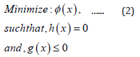
where, ‘x’ is the design variable that can describe the competing design candidates; φ (x) is the ultimate ‘working ‘objective function; h(x) is the equality constraint (boundary condition of FEA) and g(x) are the inequality constraints, which impose specific requirements on the design variable ‘x’. It may be noted that in our case of prototype robotic gripper we will have multiple g(x). We have customized φ (x)with two-fold strictures, viz. Shape Optimization and Mass Optimization. We will elaborate this formulation in next sub- section. The ensemble optimization of the prototype gripper can be realized by combining the topology optimization (TO) module with static/modal analysis module. The constraint location, exclude regions, mass retaining percentage and other parameters are defined here, which thereafter results into improved shape of the prototype gripper. We have also used topology density tracker in order to visualize the evolution of shape during solution phase. As part of the TO module, the primary stress analysis results are plotted back for the new improved design using a novel design validation system. The present study aims at reducing the compliance of the prototype robotic gripper system through the built-in optimization capability of commercially available package. The optimal material distribution is subject to outline of initial design space and constraints (loads and boundary conditions). Thus, compliance is equivalent to strain energy, which yields higher stiffness when minimized. Minimization of compliance means minimization of work done, which results into lesser amount of energy stored in the gripper system and finally, the ensemble gripper unit becomes rigid.
Mathematical Model of the Developed Topology Optimization (TO)
Topology Optimization (TO) becomes active by providing a
solution file of the erstwhile static analysis of the prototype robotic
gripper. As part of TO, we need to functionalize its settings like
minimum number of iterations, convergence accuracy and the
solver type. On completion of the static analysis, the maiden step in
executing TO begins by comprehending the load design objectives.
The later step is essentially the objectives of the optimization i.e.,
to minimize the bulkiness of the part while upholding stress and
deflection within quantified values. We define specified domains
(i.e., optimization region) into module where we need to select two
paradigms, viz.: [i] the bodies that are to be optimized and [ii] the
excluded region for the faces (i.e., bodies to remain unaffected).
We have set the optimization type to ‘density-based lattice
optimization’, which is nothing but simply reduction of mass of the
robotic gripper system. We have kept the objective of TO as default,
i.e., to minimize the compliance of the gripper ensemble, with
respect to both static as well as modal analysis. Our customized TO
module is hitherto attributed with the elimination of undesirable
material from the gripper body but the final form rest on the initial
density of mesh used for the FEA. Our niche objective functions are
accessible to optimize the shape and size of the prototype robotic
gripper system, wherein 20% material removal is done taking into
consideration of ease of manufacturing.
In-line with the proposition of eqn. (2), we can extend the
lemma of our objective function as:
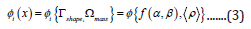
where, i: iteration number of the TO-module; ( ) i φ x ultimate
working objective function; shape Γ : ‘shape function’ sub-set of the
objective function; mass Ω : ‘mass function’ sub-set of the objective
function; f: functional form of the shape function; α ensemble
length of the prototype gripper system; β : ensemble breadth of
the prototype gripper system; ρ : density vector of the materials
of manufacturing of the gripper sub-systems.
Equation (3) is the backbone of our development of the TOmodule,
which will lead to the following transcendental equation
for the objective function:

were, V: volume fraction of the gripper system at the itch. iteration of the objective function; dV: infinitesimal volume of the FE-mesh under consideration at the itch. iteration; u (δ ) : generic length function of the gripper system at the ith. iteration. Naturally, the surface integral of eqn. (4) is deducible via FEA, and the outcome will get subsumed in the customized code of the TO-module. Let us now take an insight to the equality constraint, h(x) of eqn. (2). The TO-module of the prototype robotic gripper essentially aims at the internal & external force balance under run-time sequences of grasp. We have two external force functions of the gripper system, so far as the real-time grasp as well as its stability is concerned. In order to compensate the external force function, we have five internal force functions. The external force functions of the gripper system are: i] payload & ii] tare-weight. These force functions are uni- directional co-planar force vectors as per the standard kinematics of the prototype gripper. Besides, these forcing functions are static loads that act through a specific ‘point’ in the plane (‘point-loading’). In contrary, the internal force functions of the gripper system are: i] reaction force at the fixed end of the gripper / attachment to the robot wrist; ii] force due to the torsion produced while grasp is in process; iii] gear-meshing force including backlash; iv] slip force at the jaws (during grasp) and v] constitutive force during grasp. Hence, we can formulate the expanded expression of h(x) as below:
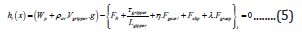
were, hi(x): equality constraint of the TO at ith. iteration; i: iteration number; WP: payload to be gripped; av ρ : average density of the gripper; Vgripper: ensemble volume of the gripper; g: acceleration due to gravity; FR: reaction force at the fixed end of the gripper / attachment to the robot wrist; gripper τ : torsion produced while grasp is in progress; Lgripper: length of the gripper in plane (horizontal distance between the jaw-tip & fixed-end of the gripper); Fgear: gear meshing force; Fslip: slip force at the jaws (during grasp); Fgrasp: constitutive force during grasp; η,λ appropriate factors for the respective forcecomponents. It may be noted that the force expressions inside first bracket signify external force functions and those inside the second bracket are the internal force function components at the ith. iteration. It is also obvious that external force functions will remain unaltered throughout the iterative process, but internal force components can vary from one iteration to the other. Let us investigate the situation with the inequality constraints now. At the outset, we may take a note that g(x) is valid for all FE-segments, be it tetrahedral or hexahedral. In our case, g(x) is largely a function of material density and infinitesimal volumes of the FE-elements together. However, g(x) in our case is linear and not a joint function. Mathematically, we can express these infinitesimal volumes and masses thereof as shown below:
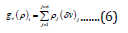
were,  : infinitesimal mass of the topology optimized section
of the gripper at itch. iteration.
i: iteration number of the TO-module; ρj
: density of the
material of the jth. segment of the topology optimized section
of the gripper; vj δ : infinitesimal volume of the jth. segment of the
topology optimized section of the gripper. We can now extend the
proposition of eqn. (6) to formulate the analytical paradigm of g(x)
for the first two levels of iterations as under:
: infinitesimal mass of the topology optimized section
of the gripper at itch. iteration.
i: iteration number of the TO-module; ρj
: density of the
material of the jth. segment of the topology optimized section
of the gripper; vj δ : infinitesimal volume of the jth. segment of the
topology optimized section of the gripper. We can now extend the
proposition of eqn. (6) to formulate the analytical paradigm of g(x)
for the first two levels of iterations as under:
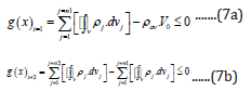
where, g(x)i=1 : inequality constraint of the TO-module at first level of iteration; g(x)i=2 : inequality constraint of the TO-module at second level of iteration; i: iteration number of the TO-module; j: number of FE-segments of the prototype gripper that are involved in the optimization process; n1: total number of FE-segments of the gripper that are involved in the first level of iteration; n2 : total number of FE-segments of the gripper that are involved in the second level of iteration j ρ : material density of the jth. FE-segment that is involved in the optimization process; dvj: infinitesimal volume of the jth. FE-segment during de-featuring process that is involved in the TO-module; av ρ : average value of the density of the ensemble gripper prior to de-featuring process; V0: volume of the gripper system prior to de-featuring as well as optimization process. Based on the syntax of eqn. (7b), we can deduce the generalized form of the iterative method of evaluating g(x) as per the following lemma:
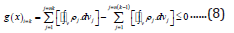
where, ‘k’ signifies the generalized iteration level of the TOprocess. Accordingly, total number of FE-segments that are involved at the kth. level of iteration is ‘nk’ and that at the preceding iteration level is ‘n(k-1)’. Rest of the symbols have same nomenclature, as detailed under eqns. (7a) & (7b). Thus, the numerical evaluation of g(x) is iterative, and the subtleness of the iteration-levels signifies the accuracy of the TO-process as a whole. The iterative process for the evaluation of g(x) will continue till the last iteration and the mathematical condition for the closure of the iterative process will be denoted by the following lemma as necessary and sufficient condition:
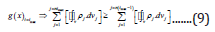
It is to be noted that in all the previous formulations, i.e., eqns. (6) to (9), the legend, j δ v or ‘ j dv ’ (under integral) signifies de-featured volume of the particular FE-segment. This is very important proposition of our TO-module wherein each level of iteration is based on the successive de-featuring of the geometry / topology of the robotic gripper system. Let us now take a re-look at the physics behind the design of the prototype gripper via TOroute. We have deliberated that the topology optimization for the present case is equivalent to minimization of system compliance and maximization of natural frequency of vibration of the gripper system. We will re-christen the phenomenon of system compliance for the prototype gripper using the principle of virtual work and do the same later for the derivation of natural frequency of vibration as well. We can expand the formulae of the system compliance and natural frequency of vibration for the gripper assembly as shown below:
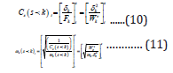
were,  compliance of the kth. FE-segment at ith. level of
iteration of the TO-module;
compliance of the kth. FE-segment at ith. level of
iteration of the TO-module;  natural frequency of vibration
of the kth. FE-segment at ith. level of iteration of the TO-module;
s: segment of the FEA (comprising hexahedral and/or tetrahedral
elements); k δ
: deflection of the kth. FE-segment at ith. level of
iteration; Fk: Force of interaction pertaining to the kth. FE-segment
at ith. level of iteration;
natural frequency of vibration
of the kth. FE-segment at ith. level of iteration of the TO-module;
s: segment of the FEA (comprising hexahedral and/or tetrahedral
elements); k δ
: deflection of the kth. FE-segment at ith. level of
iteration; Fk: Force of interaction pertaining to the kth. FE-segment
at ith. level of iteration;  mass of the kth. FE-segment at ith.
level of iteration; W v: virtual work done by the kth. FE-segment at
ith. level of iteration. Now, by the fundamental principle of our TOmodule,
i.e., minimization of compliance or maximization of natural
frequency, we will get the analogy of maximization of ‘W v’. We will
take a look at the physical insight of this virtual work at a specific iteration-level, with reference to the formulation of ‘h(x)’ in eqn. (5).
We can demarcate two types of forcing functions that are analogous
to ‘internal forcing functions’ and ‘external forcing functions’ of eqn.
(5). These forcing functions are now grouped on the basis of the
‘action’ on the FE-segments. It may be noted that all constituents
of internal forcing functions are essentially distributed over the
FE- segments and each one of those forcing functions is responsible
for a finite amount of ‘displacement’ of the FE- segments, whatever
infinitesimal the magnitude becomes. These distributive forcing
functions are co-planar vectors and hence displacements generated
thereof are also vectors in the same plane. Thus, the virtual work
done by the FE-segments due to the actuation of these distributive
forcing functions is additive. On the other hand, the effect of the
external forcing functions on the FE-segments is tractive by nature
that can be computed as force per unit area of the FE-segments.
Hence, we can formulate the analytical model of the total virtual
work done by the FE-segments collectively as:
mass of the kth. FE-segment at ith.
level of iteration; W v: virtual work done by the kth. FE-segment at
ith. level of iteration. Now, by the fundamental principle of our TOmodule,
i.e., minimization of compliance or maximization of natural
frequency, we will get the analogy of maximization of ‘W v’. We will
take a look at the physical insight of this virtual work at a specific iteration-level, with reference to the formulation of ‘h(x)’ in eqn. (5).
We can demarcate two types of forcing functions that are analogous
to ‘internal forcing functions’ and ‘external forcing functions’ of eqn.
(5). These forcing functions are now grouped on the basis of the
‘action’ on the FE-segments. It may be noted that all constituents
of internal forcing functions are essentially distributed over the
FE- segments and each one of those forcing functions is responsible
for a finite amount of ‘displacement’ of the FE- segments, whatever
infinitesimal the magnitude becomes. These distributive forcing
functions are co-planar vectors and hence displacements generated
thereof are also vectors in the same plane. Thus, the virtual work
done by the FE-segments due to the actuation of these distributive
forcing functions is additive. On the other hand, the effect of the
external forcing functions on the FE-segments is tractive by nature
that can be computed as force per unit area of the FE-segments.
Hence, we can formulate the analytical model of the total virtual
work done by the FE-segments collectively as:
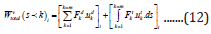
were,  total virtual work done by all of the ‘k’ FEsegments
at the itch. level of interaction of the TO- module; m: total
number of FE-segments; F d: distributive forcing function at the kth.
FE-segment at the ith. level of iteration; u d: displacement of the
kth. FE-segment due to the distributive forcing function at the ith.
level of iteration; F t: Tractive force per unit area at the kth. FEsegment
at the itch. level of interaction; u t: displacement of the kth.
FE-segment due to the tractive forcing function at the itch. level of
interaction; ds: infinitesimal surface area at the kth. FE-segment at
the itch. level of interaction.
total virtual work done by all of the ‘k’ FEsegments
at the itch. level of interaction of the TO- module; m: total
number of FE-segments; F d: distributive forcing function at the kth.
FE-segment at the ith. level of iteration; u d: displacement of the
kth. FE-segment due to the distributive forcing function at the ith.
level of iteration; F t: Tractive force per unit area at the kth. FEsegment
at the itch. level of interaction; u t: displacement of the kth.
FE-segment due to the tractive forcing function at the itch. level of
interaction; ds: infinitesimal surface area at the kth. FE-segment at
the itch. level of interaction.
An Insight to the Developed Topology Optimization (TO)
We have paid due attention towards reaching out a tradeoff
between stiffness parameter of the prototype robotic gripper
and damping behavior of the material of fabrication of the same.
While stiffness is a geometric property, damping is an intrinsic
property of the material of fabrication. We have found that the
compliance objective of our TO module is very beneficial as mass
and volume can be measured with the response constraints. Default
response constraint is to retain 50% mass of the prototype robotic
gripper system. Our TO module uses global/local Von-Mises stress
constraint that meets the stress criteria for the prototype robotic
gripper. As per the TO proposition, stress constraint can be set for
optimized regions or exclude regions. Maximum displacement can
also set for the model under displacement constraint. Similarly,
maximum reaction forces for the model can be set using reaction
force constraints. Besides usual strictures as stated, our TO module
is also equipped with manufacturing constraints, which provides
the designer an option to uphold the bottlenecks in manufacturing
on the gripper model. Sometimes we do come across a substantial
gap between the topology optimized design and the final design
ready for manufacturing. Usually, topology optimization is used in
the initial design phase, followed by a number of post- processing
steps resulting in the final design for manufacturing. However, we
have augmented these post- processing stages in our customized
TO-module so that we can review the final design for manufacturing
as well. Our TO-module is therefore capable of pin-pointing the
local failure criteria also as part of the manufacturing design
semantics. Under the ambit of our TO module, the maximum and
minimum member size can be set as well as pull-out direction can
be demarcated for ensuring preclusions against undercuts. Cyclic
symmetries can also be coupled with the pull-out direction as well
as extrusions.
We have incorporated ‘density tracker’ in TO-outcome that can
be used to envisage the optimization in real- time. The outcome of
the customized ‘density tracker’ is in the form of STL file, which can
be exported for CAD operation and validation. By virtue of ‘density
tracker’, the STL file and CAD model are transferred to the validation
system of the TO-module. Editing operations are then performed
on the model and finally the same is converted to solid model from
the erstwhile STL format. Then after, we open the so-called TOgenerated
‘geometry’ of the prototype gripper in FE-pre-processor
and performs alteration and essential modification. The optimized
model of the robotic gripper, so generated, was then allowed to be
meshed again for analysis. Besides, load and boundary conditions
were applied afresh. The edited & ‘optimized’ model was solved
again and it was validated so as to ensure that the design objective
has been met. Nonetheless, we needed to overcome the issue of
identifying local maxima and local minima in the TO-optimized
design for manufacturing. We have used Lagrange Multiplier for
this in a customized fashion. The method is very useful as it allows
the optimization to be solved without explicit parameterization in
terms of the constraints. In our case, the load constraints are very
vital (refer eqn. 5) and the subtleness of the forcing function can
alter the result. Hence, we have used Lagrange Multiplier technique
in order to have the gradients of local minima linear. Based on the
linearization of the gradient of the load constraint, we have used
Lagrange Multiplier method for the volume constraint as well. The
local minima for the volume constraint have become effective in
restricting the ensemble mass of the prototype gripper system to a
significant extent. In order to cross-check the validity, the solution
of original and optimized model was equated. However, on the
flip side, multiple iterations were performed to make the solution
converge. Thus, TO process is more computationally expensive than
a normal solution solver that ANSYS® uses for the finite element
solution. Once this iterative solution process is done, we launched
the design validation system to accomplish the final validation.
Both un-optimized and optimized model were moved to the design
validation system. This was carried out essentially to edit the
optimized geometry, as the optimization tool has eradicated excess
material from the model. As a final cosmetic makeover to the TOoutcome
of the prototype robotic gripper, we performed minor
editing to manipulate or smoothen the geometry accordingly.
Figure 13 illustrates the overall flow chart of the TO-algorithm, as
used in the design optimization of the prototype robotic gripper.
Figure 13: Flow Chart of the Topology Optimization Algorithm.

Results of Topology Optimization
Table 4: Mesh Statistics of the FEA after Topology Optimization.

Table 4 presents the improvised data on ‘nodes’ and ‘elements’ after TO-module was invoked for the design optimization of the prototype robotic gripper. We can check the improvement (with optimization), in comparison to the data of Table 1. We have observed a massive reduction of nodes from the final defeatured model to the topology optimized model that is 76%. This is significant and proves the efficiency of our customized TOmodule. However, we haven’t sacrificed much in terms of number of ‘elements’ (15% reduction), which shows that equality constraint of the TO-module (internal & external forcing functions) has been paid due importance. As the usage of the prototype gripper is heavily dependent on the grasp synthesis and grasp prehension, our TOmodule has not compromised with the number of elements in FEA. That is why, there is small reduction in number of elements but heavy trimming in number of nodes. The large reduction in number of nodes is also due to augmentation of design for manufacturing in our TO-module, wherein many insignificant nodes from the perspective of manufacturing have been chopped off. The crisp FE-elements have been found effective in better realization of the slip-resistant contiguous grasp in real-time. The outcome of the Topology Optimization module, supplemented by ‘density tracker’ is illustrated in Figure 14 below. The optimized mesh geometry of the prototype gripper is shown in Figure 14a, while the screenshot of final edited CAD of the gripper is presented in Figure 14b. Thus, the topology optimization has helped to reduce the overall weight the gripper and it has improved overall mechanical design as well. The improved design has removed unwanted material that has also reduced the overall elements in the model as discussed in Table 4. Table 5 presents the final dimensions and material for manufacturing of the various constituents of the topology optimized prototype robotic gripper system.
Table 5: Final External Dimensions and Material for Manufacturing of the Components of the Topology Optimized Prototype Robotic Gripper.

Figure 14a: Design of the Prototype Gripper after Topology Optimization: Optimized Mesh Geometry.

Figure 14b: Design of the Prototype Gripper after Topology Optimization: Final Edited CAD Model.

Let us now take a closer look over different components of the prototype gripper system, post topology optimization. Once the optimization is performed, the modifications are updated on the existing CAD design. By this process, the drawings of the new parts are made available that are suitable for manufacturing. Figure 15a shows the CAD model of the optimized jaw and Figure 15b shows the same for the original jaw. It may be pointed out that TO-iterations have incorporated number of groves and slots in the jaws so as to make the jaw light-weighed. Special attention has been paid for this iterative design of the grooves and slots of the jaws so as to machine those with ease. TO-module has made the jaw design perfect by reducing the weight of the jaws, which can be compared through visual inspection of the screenshots of Figures 15a,15b. Similarly, the optimized CAD model of the upper plate and its original CAD model are shown in Figures 16a,16b respectively. We may observe here the reduction of weight criteria has been fulfilled by providing more slots & recesses in the upper plate that has been achieved via design iterations. It may be noted that all components made up of aluminium have been optimized not only for the design but also for manufacturing. However, gears have been left out in detailed optimization because of the limitations in manufacturing. Figures 17a,17b illustrate the optimized and un-optimized CAD model of the external sector gear respectively. The curvilinear-shaped large recess of the optimized CAD may be referred, which is the outcome of multiple iterations on the design of the sector gear.
Figure 15a: Performance of the Topology Optimization of the Prototype Gripper: CAD Model of the Optimized Jaw.

Figure 15b: Performance of the Topology Optimization of the Prototype Gripper: CAD Model of the Original Jaw.

Figure 16a: Performance of the Topology Optimization of the Prototype Gripper: CAD Model of the Optimized Upper Plate.

Figure 16b: Performance of the Topology Optimization of the Prototype Gripper: CAD Model of the Original Upper Plate.

Figure 17a: Performance of the Topology Optimization of the Prototype Gripper: CAD Model of the Optimized External Sector Gear.

Figure 17b: Performance of the Topology Optimization of the Prototype Gripper: CAD Model of the Original External Sector Gear.

We may highlight at this juncture that all the constituent parts have been optimized keeping courtesy on the stress contour. In fact, reduction of run-time stress as well as residual stress is of utmost importance in robotic systems in general and particularly, for robotic grippers. Besides, gradient-based topology optimization with many local (stress) constraints becomes computationally expensive. Nonetheless, we had to be cautious as several difficulties needed to be cajoled in our stress-constrained topology optimization. The basic strategy in our TO-iteration process has been to exclude the boundaries of the parts. In lieu of this, scope was given to optimize the part in its thickness direction. This has been an important consideration of the entire iteration scenario keeping in mind the manufacturing process (es). As a result of our customization of the iterative TO- module, the manufacturing became easy as the grooves and slots were easily created in single setting of the machine tool. In fact, the design iterations for the grooves and slots in various components were created in such a manner so that those parts were not required to be moved for grooving or slotting separately along the length- wise direction of the gripper. This was a crucial judgement for the iteration in TOmodule that resulted in the reduction of the manufacturing cost. The final optimized model of the prototype robotic gripper (postiterations & design for manufacturing combined) is shown in Figure 18. We may observe that most of the mass has been removed from the parts without affecting the functional requirements and load constraints. An assessment of the final tare weight of the gripper is made, as detailed in Table 6. The mass of the ensemble gripper system is reduced by almost 20%.
Figure 18: Final Optimized Model of the Prototype Robotic Gripper.

Table 6: Assessment of the Mass of the Gripper Parts and Assembly.

Table 7: Comparison of Deformation and Stress of the Prototype Gripper Post-Topology Optimization.

The Topology Optimization module has been instrumental in assessing the engineering parameters of the prototype robotic gripper in an elegant way. We have evaluated the rheology parameters (deformation & stress) of the gripper assembly, postoptimization and the results are presented in Table 7. Quantitatively, both deformation and stress for the optimized model are lower in comparison to the original model. The variation of stress along the thickness of the sector gear has been studied as part of the topology optimization process. The ‘thicknesses or width of the sector gear has been selected for the study as accumulation of stress occurs at that very portion. The variation of the said stress is plotted in Figures 19a,19b, respectively for the un-optimized and optimized model of the prototype gripper. The plots of Figure 19 show the variation of stress of the sector gear of the gripper at the location where maximum stress occurs. The gear has a total thickness of 8 mm; thus, the plot shows stress up to 8 on abscissa. The stress developed in the Optimized original model shown in Figure 19a has stress values of about 45.991MPa varying along the thickness. Similarly, the plot in Figure 19b shows the stress value of 42.621Mpa varying along the thickness in un-optimized model.
Figure 19a: Variation of Stress along the Thickness of the Sector Gear: Optimized Model.

Figure 19b: Variation of Stress along the Thickness of the Sector Gear: un-optimized Model.

It may be observed that we have orchestrated our effort towards topology optimization of the prototype gripper with respect to static analysis only. Since the modal analysis of the unoptimized model of the gripper has showed relatively large values of the natural frequency of vibration, we do not attempt topology optimization further. Besides successful handshaking with the static analysis, the optimized prototype gripper model was made ready for manufacturing to the best possible extent. We have duly undertaken the manufacturing of the design-optimized robotic gripper as per the finalized design attributes. For example, laser techniques were invoked to cut the thin parts and CNC/VMC (Vertical Machining Centre) were used for machining the rest of the structure. Nonetheless, we have completed the manufacturing of the ‘test’ gripper as per the original design, i.e., before processing of the optimization routine. Figure 20 shows the photographic view of the curvilinear-jaw prototype ‘test’ robotic gripper, postmanufacturing. The realization of this ‘test’ gripper has helped us doing a vast round of grasp analysis that are essential to ascertain the deploy ability of this novel gripper for material handling in industry.
Figure 20: The Photographic View of the Prototype Robotic Gripper Post-manufacturing.

Conclusions
In conjunction with topology optimization, the modal analysis
of the prototype robotic gripper revealed that the model is rigid
enough as the natural frequencies are much higher. Besides saving
of material and fabrication cost, product aesthetics was improved
by this novel methodology of topology optimization. Our module
of topology optimization has resulted successfully in attaining the
maximum rigidity to the prototype gripper system, along with
mass control criteria. The topology optimization has resulted in
minimizing the compliance, along with reduction of volume & tare
weight. The customized module of iterative topology optimization
has resulted in design for manufacturing as well as physical
realization of real-life ensemble hardware of a novel lightweight
curvilinear-jaw robotic gripper.
The successful prototyping of this curvilinear-jaw robotic
gripper has been attributed to various real-life contigutive slip-free
grasp of objects, both in stand-alone mode as well as integrated
with robotic manipulator [for details, please refer to the following
video-clips:
a) https://www.youtube.com/watch?v=048N9Xqsseg;
b) https://www.youtube.com/watch?v=29gz3_Im6lg;
c) https://youtu.be/29gz3_Im6lg;
https://www.youtube.com/watch?v=E5G_veak8tU].
References
- Kishan Anand, AnadiMisra (2015) Topology Optimization and Structural Analysis of Continuous Linear Elastic Structures Using Optimality Criterion Approach in ANSYS. International Journal of Innovative Research in Science, Engineering and Technology 4(6): 2347-6710.
- Adrian Ghiorghe (2010) Optimization Design for the Structure of a RRR type Industrial Robot. UPB (Universitatea Politehnica Bucuresti) Science Bulletin Series D 72(4): 121-128.
- Anmol Pandey, Rituparna Datta, Bishakh Bhattacharya (2015) Topology Optimization of Compliant Structures and Mechanisms Using Constructive Solid Geometry for 2-D and 3-D Applications. Springer Verlag Berlin Heidelberg.
- Sudhanshu Tamta, Rakesh Saxena (2016) Topological Optimization of Continuum Structures Using Optimality Criterion in ANSYS. International Research Journal of Engineering and Technology (IRJET) 3(7): 1483-1488.
- Gunwant D, Misra A (2012) Topology Optimization of Sheet Metal Brackets Using ANSYS. MIT International Journal of Mechanical Engineering 2(2): 119-125.
- CD Chapman (1994) Structural Topology Optimization via the Genetic Algorithm. Thesis MS Massachusetts Institute of Technology USA.
- Kishan Anand, Anadi Misra (2015) Topology Optimization of Beam Supported at Ends and Elastic Plate with Central Elliptical Hole Using Optimality Criteria Approach in ANSYS. International Journal for Research in Emerging Science and Technology 2(5): 241-247.
- Caner Demirdogen, Jim Ridge, Paul Pollock, Scott Anderson (2004) Weight Optimized Design of a Front Suspension Component for Commercial Heavy Trucks. Proceedings of the SAE Commercial Vehicle Engineering Congress and Exhibition Chicago Illinois USA pp: 400-410.
- Robin Larsson (2016) Methodology for Topology and Shape Optimization: Application to a Rear Lower Control Arm. Master’s Thesis in Applied Mechanics, Department of Applied Mechanics Chalmers University of Technology Goteborg Sweden.
- Kim JH (2018) Design and Optimization of a Robotic Gripper for the FEM Assembly Process of Vehicles. Mechanism and Machine Theory 129: 1-16.
- Rituparna Datta, Shikhar Pradhan (2015) Analysis and Design Optimization of a Robotic Gripper Using Multi- Objective Genetic Algorithm. IEEE Transactions on Systems, Man, and Cybernetics: Systems 46: 1-11.
- Chih Hsing Liu (2019) Topology and Size–Shape Optimization of an Adaptive Compliant Gripper with High Mechanical Advantage for Grasping Irregular Objects. Robotica 37(8): 1383-1400.
- Dedao Liu (2020) A Post-processing Method to Remove Stress Singularity and Minimize Local Stress Concentration for Topology Optimized Designs. Advances in Engineering Software 145: 1-13.
- Alaa Hassanand Mouhammad Abomoharam (2017) Modeling and Design Optimization of a Robot Gripper Mechanism. Robotics and Computer-Integrated Manufacturing 46: 94-103.
- Chara Lanni (2019) An Optimum Design Algorithm for Mechanisms in Two-Finger Grippers. Proceedings of the 13th. WSEAS International Conference on SYSTEMS pp: 63-70.
- Walter G Bircher (2017) A Two-Fingered Robot Gripper with Large Object Reorientation Range. Proceedings of the IEEE International Conference on Robotics and Automation (ICRA) Singapore pp: 3453-3460.
- Supriya Sahu, BB Choudhury (2017) Static Analysis of a 6 - Axis Industrial Robot using Finite Element Analysis. International Journal of Mechanical Engineering and Technology (IJMET) 8(3): 49-55
- Prathamesh Warude, Manoj Patel, Pankaj Pandit, Vikram Patil, Harshal Pawar, et al. (2019) On the Design and Vibration Analysis of a Three-Link Flexible Robot Interfaced with a Mini-Gripper. Lecture Notes in Mechanical Engineering--Recent Trends in Wave Mechanics and Vibrations Springer pp: 29-45.
- A Bicchi, V Kumar (2000) Robotic Grasping and Contact: A Review. Proceedings of the IEEE International Conference on Robotics and Automation pp: 348-353.
- Sachin Badadhe (2018) FEM Based Dynamic Analysis of Robot End Gripper Mechanism. International Journal of Engineering Science Invention (IJESI) 7(11): 50-67.
- Patakota Venkata Prasad Reddy (2013) A Review on Importance of Universal Gripper in Industrial Robot Applications. International Journal of Mechanical Engineering & Robotics and Research 2(2): 255-264.
- T Crytser (1995) Finite Element Design of Manipulator-Coupled Spacecraft for a Research Testbed. Journal of Intelligent and Robotic Systems 13: 75-91.
- Myounghoon Shima, Jung Hoon Kimb (2018) Design and Optimization of a Robotic Gripper for the FEM Assembly Process of Vehicles. Mechanism and Machine Theory 129: 1-16.
- Duc Chuong Nguyen, Thanh Vu Phan (2018) Design and Analysis of a Compliant Gripper Integrated with Constant-Force and Static Balanced Mechanism for Micro Manipulation. Proceedings of the 4th. International Conference on Green Technology and Sustainable Development GTSD pp: 291-295.
- Joshua Pinskier (2016) Design, Development and Analysis of a Haptic-Enabled Modular Flexure-based Manipulator. Mechatronics 40: 156-166.
- Ramish Chouhan, Farah Kanwal (2014) Design and Development of a Prototype Robotic Gripper. Proceedings of the 2014 International Conference on Robotics and Emerging Allied Technologies in Engineering (iCREATE) Islamabad Pakistan pp: 317-320.
- Harshal Pawar, Chinmay Nate, Manoj Patel, Pankaj Pandit, Vikram Patil, et al. (2019) Design, Dynamic Simulation and Test Run of the Indigenous Controller of a Multi-Gripper Revolute Robot by Minimizing System Trembling. Lecture Notes in Mechanical Engineering--Recent Trends in Wave Mechanics and Vibrations, Springer.
- Roy Debanik (2020) Design, Modeling, and Indigenous Firmware of Patient Assistance Flexible Robotic System- Type I: Beta Version. Advances in Robotics and Mechanical Engineering 2(3): 148-159.


-

Mark E Smith
Bio chemistry
University of Texas Medical Branch, USA -

Lawrence A Presley
Department of Criminal Justice
Liberty University, USA -

Thomas W Miller
Department of Psychiatry
University of Kentucky, USA -

Gjumrakch Aliev
Department of Medicine
Gally International Biomedical Research & Consulting LLC, USA -

Christopher Bryant
Department of Urbanisation and Agricultural
Montreal university, USA -

Robert William Frare
Oral & Maxillofacial Pathology
New York University, USA -

Rudolph Modesto Navari
Gastroenterology and Hepatology
University of Alabama, UK -

Andrew Hague
Department of Medicine
Universities of Bradford, UK -

George Gregory Buttigieg
Maltese College of Obstetrics and Gynaecology, Europe -

Chen-Hsiung Yeh
Oncology
Circulogene Theranostics, England -
.png)
Emilio Bucio-Carrillo
Radiation Chemistry
National University of Mexico, USA -
.jpg)
Casey J Grenier
Analytical Chemistry
Wentworth Institute of Technology, USA -

Hany Atalah
Minimally Invasive Surgery
Mercer University school of Medicine, USA -

Abu-Hussein Muhamad
Pediatric Dentistry
University of Athens , Greece
