Lupine Publishers Group
Lupine Publishers
Menu
ISSN: 2690-5779
Research ArticleOpen Access 
Modal Analysis of Horinzontal Axis Wind Turbine Lattice Tower Volume 1 - Issue 5
Ogbeide OO and Uwoghiren FO*
- Department of Production Engineering Faculty of Engineering, University of Benin, Nigeria
Received: March 03, 2022 Published: March18, 2022
Corresponding author: Uwoghiren FO, Department of Production Engineering Faculty of Engineering, University of Benin, PMB 1154, Benin City, Edo State, Nigeria
Abstract
Renewable energy sources especially wind energy have gained much attention due to the recent energy crisis and the desire to obtain clean energy. Due to vibration, small wind turbines are usually not installed on the structures since the vibration of a wind turbine tower can attain resonance. Resonance is often a contributing factor to many of the vibration problems that occur in wind turbine tower. Small wind turbine exists on National Centre for Energy and Environment, University of Benin with power of 1.0 kW, which creates more vibration on running condition. By reducing vibration in the wind turbine, vibration transformation on the structure will also be avoided so that we can improve performance, lifetime and power quality of wind turbine. Vibration analysis on the small wind turbine model was carried out by performing modal analysis in ANSYS workbench. Influences of the rotating speed, wind velocity and the aerodynamic loads on natural frequencies were captured. Modal analysis using finite element software ANSYS MODAL established resonance with system frequency less than the lowest of ten mode frequencies 0.78394Hz, of the tower. With these results, it was concluded that the tower is not expected to fail due to the impact of the wind speed on the blade of the wind turbine.
Keywords: Modal analysis; Vibration; Natural frequency; Wind turbine tower; Deformation and Finite element method.
Introduction
Before designing a wind turbine system and structures for good vibratory performance, it is important to understand the mode frequency, mode shape, and amplitude of the vibratory characteristic of the system [1]. A dynamic system, when given an initial disturbance and allowed to execute free vibrations without a subsequent forcing excitation will tends to do so at a particular preferred frequency and maintaining a particular preferred geometric shape [2] This frequency is called natural frequency of the system and the corresponding shape of the moving parts of the system is referred to as mode shape. Any arbitrary motion of a vibrating system can be represented in terms of its natural frequencies and mode shape [3] The subject of modal analysis is concerns with the determination of natural frequencies and mode shapes of a dynamic system. Once the modes are determined, they can be used to understand the dynamic nature of the systems, and also in design and control. From Literature researchers have examined the dynamics of wind turbines to optimize their performance [4]. Kessentini et al. [5] developed a mathematical model of a horizontal axis wind turbine (HAWT) with flexible tower and blades. The equations of motion were derived using the extended Hamilton’s principle. The eigenvalue problem was solved in closed form and numerically using the Differential Quadrature Method (DQM). Their findings showed that dynamic tower blade coupling cannot be considered insignificant. [6] developed a modified version of the mathematical model in which he took into consideration the fluid-solid interaction via wind loads that induce the rotation of the hub and flapping vibrations of tower and blades. Wang et al. [7] proposed a mixed flexible rigid multibody analytical model that employed the thin-walled beam theory that was superior to the traditional 1D beam finite element when applied to compute the dynamic behaviour of wind turbines. The developed model was applied to predict the dynamic performance of a wind turbine system. The kinetic and potential energy terms of each flexible body and rigid body forms the wind turbine system’s governing equation. The mode shapes were then obtained from the free vibration solution while the distributions of dynamic stress and displacement of the tower and rotor were calculated from the forced vibration response analysis. Ping et al. [8] applied numerical finite element modelling to determine the frequencies and mode shapes of wind turbine blades. In addition, dynamic stresses were computed for the root zone of the blades using the finite element method. The resulting dynamic stresses were used to estimate the blade fatigue, in order to make an optimal design of the blades that resist fatigue and being energetically efficient. Peeters et al. [9] applied finite element model of wind turbines using an assembly of beam elements in ANSYS. They validated their model on a real wind turbine and relevant dynamic analysis of in-situ-measured responses. Manzato et al. [10] used modal monitoring of wind turbine blades, which was primarily based on the determination of Eigen frequencies. In addition, they combined the global modal methods with locally sensitive monitoring methods, based on guided elastic waves developed a finite element model for modal analysis of a 55-kW direct-drive permanent-magnet generator to confirm its inherent frequency and vibration mode. However, the wind turbine tower is an important component of wind turbine. The weight of the wind turbine is very big, sometimes; it is even bigger than the lower tower. In order to get more wind, the tower is generally very high. So, it is very easy to produce resonance phenomenon, which can cause horizontal amplitude [11]. In designing a tower, resonance phenomenon is design out or avoided. However, in the process of the use of wind turbine, some manufacturers change the model of wind turbine in pursuit of economic efficiency, thus, resulting in a resonance phenomenon which causes the destruction of the tower [2] As the support structure of the wind turbine, the tower bears alternating loads of wind when the wind turbine runs [1]. Wind turbines are installed in places where wind resource is rich. Though wind turbines supply energy using the kinetic energy of the wind and save non-renewable energy. The tower is the support structure of the wind turbine and the alternating loads that the tower bears are complex. There have been many accidents caused by tower faults in different wind farms during the past years [12].
To make sure the tower is suitable for the wind turbine, structural analysis of the tower is essential. Natural frequency of the wind turbine tower which should be different from the frequency of the rated speed, can be provided by modal analysis, and this will help to avoid resonance [1]. To ensure the reliability of the wind turbine, it is necessary to carry out modal analysis on the tower, and this would prevent the natural frequency of the tower close to the rated speed of wind turbine. In this research work, modal analysis of a wind turbine tower of University of Benin Energy Research Centre was carried out using FEA to study the natural frequencies and mode shapes of different geometries for the construction of a wind turbine tower.
Research Methodology
The modal analysis of the mast was carried out in order to investigate ten modal frequencies of vibration of the mast for case of impost force of 1000N on the top of the mast without the adaptor, generator and blade set up as well as a case where the generator, blades and adaptor is mounted on the top of the mast. The geometry was created using Autodesk inventor and imported into ANSYS design modeler using ANSYS 16. The created geometries are shown in (Figures 1 & 2) In the study, 1000N force was impost at the top of the mast without the generator, adaptor and blades. Fixed support was impost at the three bottom ends of the geometry and ten modal frequencies were studied for the two cases. Grid independent test was carried out on the complete assembly in order to ensure that the results are consistent irrespective of the grid size. Finally, three different mesh elements were done and simulated using the same setup parameters.
Result and Discussion
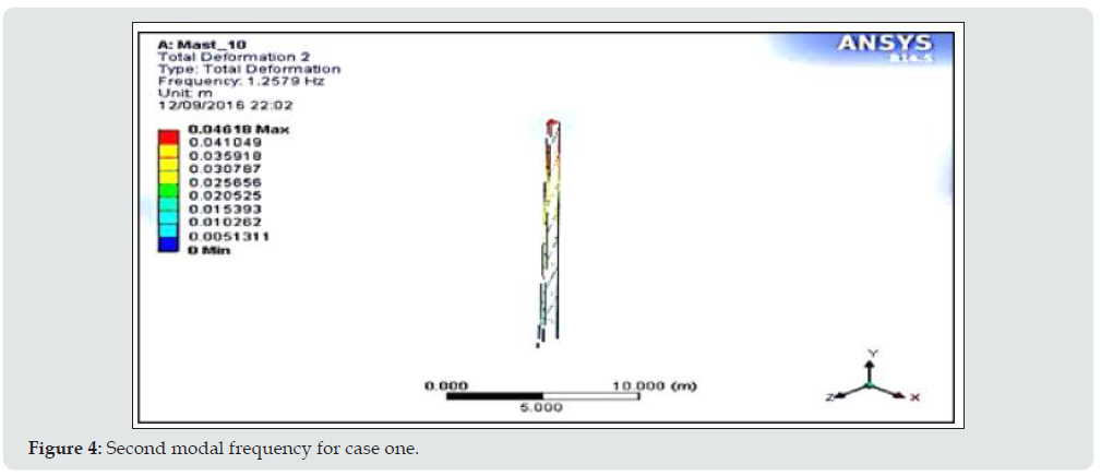
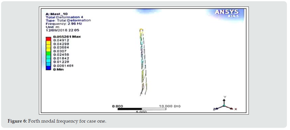
(Table 1) presents the summary of the natural frequencies (fn) and the total deformation of the wind turbine lattice tower (mast truss). Ten modes were reported. Maximum deformation of 0.57594m occur at mode 10, at a maximum frequency of 8.6435Hz, Our turbine’s design rotating speed is about 198rpm which corresponds to the rotor frequency, frotor (1p) of 0.33Hz. The first mode of the tower is 1.17Hz which is greater than the rotor frequency. Thus, the tower is categorized as soft tower, avoiding excitation of the turbine’s natural mode of vibration during the normal operation. The blade passing frequency, fbp (3p) is 6.03Hz, it lies between 6th and 7th mode of vibration. Thus, it avoids the excitation during the normal operation. However, the tower may be temporarily excited as the turbine starts up or shuts down. The rotor frequency is less than the natural frequency and the blade passing frequency, thus it avoids resonance in the installed system. The result of the first modal frequency for case one is presented in (Figure 3). For the first modal frequency for case, one as presented in (Figure 3), all the applied loads (thrust, gravity) were ignored, and the specified boundary conditions were applied with a load of 1000N. The plotted solution which is specifically the deformation of the mode shape was normalized to unity in order to generate the second to tenth modal frequency presented in Figures 4, 5, 6, 7, 8, 9, 10, 11 and 12 respectively. From the result of Figure 4, it was observed that for a frequency of 1.2579Hz, the maximum deformation recorded was 0.04618m. From the result of (Figure 5), it was observed that for a frequency of 2.8111Hz, the maximum deformation recorded was 0.054712m. From the result of (Figure 6), it was observed that for a frequency of 2.960Hz, the maximum deformation recorded was 0.05526m
From the result of (Figure 7), it was observed that for a frequency of 4.5891Hz, the maximum deformation recorded was 0.048141m. From the result of (Figure 8), it was observed that for a frequency of 5.9619Hz, the maximum deformation recorded was 0.088761m. From the result of (Figure 9), it was observed that for a frequency of 7.8952Hz, the maximum deformation recorded was 0.24806m. From the result of (Figure 10), it was observed that for a frequency of 8.0376Hz, the maximum deformation recorded was 0.26897m. From the result of (Figure 11), it was observed that for a frequency of 8.5037Hz, the maximum deformation recorded was 0.32247m. From the result of (Figure 12), it was observed that for a frequency of 8.6435Hz, the maximum deformation recorded was 0.57594m
Conclusion
Modal analysis of the mast carrying a wind turbine setup was carried out and ten modal frequencies were comprehensively studied in order to obtain the corresponding maximum deformation. Fixed support was imposed at the bottom end of the mast and the complete assembly, and the entire mast was impost a force of 1000N. From the total deformation results obtained, it was concluded that since the natural frequency of the system (0.33Hz) is less than the studied modal frequency of the simulation results, the system is not expected to fail.
References
- Hongzhu S, Zhenhua L (2015) Modal analysis of a wind turbine tower based on the finite element method. Applied Mechanics and Materials (744-746): 179-182
- Emilio DL, Simone M, Bart P, Herman VA (2013) Virtual Structural Monitoring of Wind Turbines Using Operational Modal Analysis Techniques. Key Engineering Materials (569-570): 523-530.
- Huaming L (2004). Optimization design and analysis of wind turbine tower based on the finite element method. Xinjiang: Xinjiang Agricultural University Ion.
- Radu B, Marcel S, Daniela B (2012) Modal analysis of a small vertical axis wind turbine (Type DARRIEUS). INCAS Bulletin. 4(2): 75-81
- Kessentini K, Choura S, Najar F, Franchek MA (2010) Modeling and Dynamics of a Horizontal Axis Wind Turbine. Journal of Vibration and Control. 16(13): 2001-2021.
- Manzato S, Moccia D, Peeters B, Janssens K, White JR et.al (2012) A Review of Harmonic Removal Methods for Improved Operational Modal Analysis of Wind Turbines. Proceedings of ISMA2012, International Conference on Noise and Vibration Engineering, Leuven, Belgium p. 17-19
- Michael M, Sebastian S (2014). Design Optimization of Wind Turbine Support Structures-A Review. Journal of Ocean and Wind Energy 1(1): 12-22
- Nigerian Institute for Oil Palm Research (2018) Wind log data from the month of January to the month of May 2018
- Peeters B, Van der AH (2005) A revolution in Operational Modal Analysis, Proceedings of IOMAC, 1st International Operational Modal Analysis Conference, Copenhagen, Denmark p. 26-27.
- Ping L, Huang S, Zhang J (2012) Finite Element Analysis of Static and Dynamic Characteristics of the Cylinder Wind Turbine Tower; Acta Energiae Solaris Sinica pp. 359-363 .
- Wang Y, Tao Q (1995) Dynamic Analysis of Wind Turbine Tower. Acta Energiae Solaris Sinica pp. 162-168.
- Zhao R (2010) The horizontal axis wind turbine tower vibration modal analysis. Journal of Ianzhou University of Technology. 495): 23-34.

Top Editors
-

Mark E Smith
Bio chemistry
University of Texas Medical Branch, USA -

Lawrence A Presley
Department of Criminal Justice
Liberty University, USA -

Thomas W Miller
Department of Psychiatry
University of Kentucky, USA -

Gjumrakch Aliev
Department of Medicine
Gally International Biomedical Research & Consulting LLC, USA -

Christopher Bryant
Department of Urbanisation and Agricultural
Montreal university, USA -

Robert William Frare
Oral & Maxillofacial Pathology
New York University, USA -

Rudolph Modesto Navari
Gastroenterology and Hepatology
University of Alabama, UK -

Andrew Hague
Department of Medicine
Universities of Bradford, UK -

George Gregory Buttigieg
Maltese College of Obstetrics and Gynaecology, Europe -

Chen-Hsiung Yeh
Oncology
Circulogene Theranostics, England -
.png)
Emilio Bucio-Carrillo
Radiation Chemistry
National University of Mexico, USA -
.jpg)
Casey J Grenier
Analytical Chemistry
Wentworth Institute of Technology, USA -
Hany Atalah
Minimally Invasive Surgery
Mercer University school of Medicine, USA -

Abu-Hussein Muhamad
Pediatric Dentistry
University of Athens , Greece

The annual scholar awards from Lupine Publishers honor a selected number Read More...


