


Lupine Publishers Group
Lupine Publishers
ISSN: 2641-6921
Research Article(ISSN: 2641-6921) 
Waste Heat from Exhaust Gas to Heat Passenger Mini-Bus Compartment Through Heat Pipe Volume 1 - Issue 4
Received:May 20, 2019; Published: June 06, 2019
*Corresponding author:Bahman Zohuri, Department of Electrical and Computer Engineering, University of New Mexico, United States of America
DOI: 10.32474/MAMS.2019.01.000118
Abstract
The design, construction and experimental investigation of the thermal performance of waste heat recovery in a gas-to-air heat pipe recovery system is carried out. The system under study transports waste heat from exhaust gas to an air-cooled condenser. The system consists of two rows of five inverted U-shaped gravity assisted heat pipes charged with distilled water as working fluid. Experimental results were compared with a theoretical model based on the Effectiveness-Number of Transfer Units(ε-NTU) method and were in good agreement. Recovered energy achieved 64W with a 50oC temperature difference between the inlet and outlet air in the condenser air-cooled heat exchanger. This system also has the advantage of easy assembly and disassembly.
Keywords: Heat pipe; Energy recovery; Inverted U-shaped heat pipe; Heat pipe heat exchanger
Introduction
The exhaust system collects the exhaust gases from the cylinders of a motor vehicle engine and conducts them to the rear of the car where they are discharged to the atmosphere. Modern petrol engines have a maximum thermal efficiency of about 25% to 30% when used to power a car. About 70-75% of this thermal energy is rejected as heat without being turned into useful work [1,2]. Exhaust gasses carry approximately half of this rejected heat away and the other half passes through the cylinder walls or cylinder head into the engine cooling system to be vented to the atmosphere via the cooling system radiator. Recovering the waste heat in the exhaust pipe will improve the performance of the internal combustion engine. Heat Pipes (HPs) are one of the most efficient ways to move heat, or thermal energy, from one point to another. One method is by means of a gas-to-air heat pipe heat recovery system; another method is Thermoelectric Cells (TECs). Feng Yang et al. [3] studied the feasibility of applying a heat pipe to absorb heat from exhaust gas to heat an automotive compartment. They applied steel-water heat pipes in a gas-toair heat exchanger. The experiment tested and compared the performance of a heat recovery system with theory. They stated that the result was satisfactory. In another study, Martins et al. [4] applied heat pipes to transfer heat from an exhaust pipe to TEG modules. They applied a conventional heat pipe and a buffered or Variable Conductance Heat Pipe (VCHP) to control the temperature in Thermoelectric Generator (TEG) modules. For this propose they designed various types of HPs with different working fluids. They found the main limitation was the high temperature of the exhaust pipe. To overcome this limitation, the evaporator and condenser sections of the HP were placed into holes drilled into a solid brass. A cylindrical container filled with 0.4L of water was placed on the top of the heat pipe at room temperature (25-300C). A 20L closed cylinder tank, for pressure control of the HP, was placed to control the TEGs at a temperature below 1500C. Regarding this, Orr et al. [5-7] developed and investigated the performance of a Naphthalene heat pipe type, with a temperature range between 2500C – 4500C to prevent overheating and possible explosion of the heat pipe. In addition, Orr et al. [8-9] carried out a study to investigate the thermal performance and effectiveness of heat pipes and TEG. In their research, they found that a suitable technique to increase the efficiency of fuel use in a car is to recover some of the waste heat.
Heat Pipe Description
A heat pipe is a two-phase heat transfer device with a very high effective thermal conductivity. It is a vacuum tight device consisting of an envelope, a working fluid, and a wick structure. As shown in Figure 1, the heat input vaporizes the liquid working fluid inside the wick in the evaporator section. The saturated vapor, carrying the latent heat of vaporization, flows towards the colder condenser section. In the condenser, the vapor condenses and gives up its latent heat. The condensed liquid returns to the evaporator through the wick structure by capillary action. The phase change processes and two- phase flow circulation continue as long as the temperature gradient between the evaporator and condenser are maintained, Zohuri [10]. Heat pipes function by absorbing heat at the evaporator end of the cylinder, boiling and converting the fluid to vapor. The vapor travels to the condenser end, rejects the heat, and condenses to liquid. The condensed liquid flows back to the evaporator, aided by gravity. This phase change cycle continues as long as there is heat (i.e. warm outside air) at the evaporator end of the heat pipe. This process occurs passively and there is no external electrical energy required. At the hot interface of a heat pipe a liquid in contact with a thermally conductive solid surface turns into a vapor by absorbing heat from that surface. The vapor then travels along the heat pipe to the cold interface and condenses back into a liquid – releasing the latent heat. The liquid then returns to the hot interface through either capillary action, centrifugal force, or gravity, and the cycle repeats. Due to the very high heat transfer coefficients for boiling and condensation, heat pipes are highly effective thermal conductors. The effective thermal conductivity varies with heat pipe length and can approach 100kW/(mK) for long heat pipes, in comparison with approximately 0.4 kW/(m·K) for copper. Heat pipes employ evaporative cooling to transfer thermal energy from one point to another by the evaporation and condensation of a working fluid or coolant. Heat pipes rely on a temperature difference between the ends of the pipe and cannot lower temperatures at either end below the ambient temperature, hence they tend to equalize the temperature within the pipe as illustrated in Figure 2. Heat pipes have an envelope, a wick, and a working fluid. Heat pipes are designed for very long-term operation with no maintenance, so the heat pipe wall and wick must be compatible with the working fluid. Some material/working fluids pairs that appear to be compatible are not. For example, water in an aluminum envelope will develop large amounts of non-condensable gas over a few hours or days, preventing normal operation of the heat pipe.
Figure 1: A Simple Physical Configuration of Heat Pipe.

Figure 2: Internal Schematic Heat Pipe Structure.

A heat pipe consists of three parts: the evaporator, the condenser, and an adiabatic region connecting these zones. The function of each of these three regions are first, the evaporator, where heat is supplied from an external source and liquid evaporates. Second, the condenser, where vapor condenses due to an external sink. Finally, the adiabatic section, where vapor transfers from the evaporator through an adiabatic vapor passage and liquid returns after condensation through an adiabatic wick structure [11-13]. Condensation occurs at any point where the temperature is even slightly below that of the evaporation area; the condensate is then returned by gravity and capillary action to the evaporator. The heat pipe is essentially an isothermal heat-transfer device by virtue of the reversibility of the evaporation and condensation processes. The heat pipe can be divided into three parts in a radial direction: container, wick and vapor passage. The container must be designed to withstand the vapor pressure, and this decides the wall thickness for a given material. Additionally, a high thermal conductivity wick can be used to minimize the radial temperature drop for low thermal conductivity fluid. The function of the wick is to return the liquid from the condenser to the evaporator. Figure 3 shows a cylindrical heat pipe with a liquid saturated wick lining the inner wall of the tube. The heat is conducted radially, through the wall, and via a liquid filled wick structure to the liquid/vapor interface. The liquid filled wick evaporates and vapor flows to the condenser section where it releases its enthalpy of vaporization. The liquid is transferred back to the evaporator by capillary action, which is a unique characteristic of the heat pipe. The choice of working fluid is dependent on the temperature range in which the heat pipe is required to operate. The heat pipe is closely related to a two-phase thermosiphon or thermal syphon. However, the later can only work where the evaporator is below the condenser and relies on the condensate flowing under the action of gravity rather than under capillary forces.
Figure 3: The Three Different Parts and Functions of a Heat Pipe.

Characteristics of the Heat Pipe
Characteristics of the heat pipe is as follows
a. Operates silently due to no moving parts.
b. Isothermal operation. An ability to achieve an isothermal surface of low thermal impedance, a characteristic.
c. Thermal flux transformer. The heat pipe can absorb heat at a high (or low) flux and transmit it at a low (or high) heat flux.
d. Variable conductance heat pipe (VCHP). The ability to maintain a constant source temperature under condition of varying heat input.
e. Thermal diodes. Heat can flow from the evaporator to condenser, but not vice versa.
f. Redundancy. Any pipe can be isolated without affecting the others
Different types of heat pipes
In addition to standard, Constant Conductance Heat Pipes (CCHPs), there are a number of other types of heat pipes, including:
a) Vapor Chambers (planar heat pipes), which are used for heat flux transformation, and isothermalization of surfaces.
b) Variable Conductance Heat Pipes (VCHPs), which use a Non-Condensable Gas (NCG) to change the heat pipe effective thermal conductivity as power or the heat sink conditions change.
c) Pressure Controlled Heat Pipes (PCHPs), which are a VCHP where the volume of the reservoir, or the NCG mass can be changed, to give more precise temperature control.
d) Diode Heat Pipes, which have a high thermal conductivity in the forward direction, and a low thermal conductivity in the reverse direction.
e) Thermosyphons, which are heat pipes where the liquid is returned to the evaporator by gravitational/accelerational forces.
f) Rotating heat pipes, where the liquid is returned to the evaporator by centrifugal forces.
Benefits of these devices include:
i. High Thermal Conductivity (10,000 to 100,000 W/m K)
ii. Isothermal
iii. Passive
iv. Low Cost
v. Shock/Vibration tolerant
vi. Freeze/thaw tolerant
Limitations
a) Heat pipes must be tuned to particular cooling conditions. The choice of pipe material, size and coolant all have an effect on the optimal temperatures at which heat pipes work.
b) When used outside of its design heat range, the heat pipe’s thermal conductivity is effectively reduced to the heat conduction properties of its solid metal casing alone - in the case of a copper casing, around 1/80 of the original flux. This is because below the intended temperature range the working fluid will not undergo phase change; and above it, all of the working fluid in the heat pipe vaporizes and the condensation process ceases.
c) Most manufacturers cannot make a traditional heat pipe smaller than 3mm in diameter due to material limitations.
Overall Heat Pipe Conclusion
Overall, a heat pipe is a heat-transfer device that combines the principles of both thermal conductivity and phase transition to effectively transfer heat between two solid interfaces (Figure 3). Phase-change processes and the two-phase flow circulation in the HP will continue as long as there is a large enough temperature difference between the evaporator and condenser sections. The fluid stops moving if the overall temperature is uniform but starts back up again as soon as a temperature difference exists. No power source (other than heat) is needed. In some cases, when the heated section is below the cooled section, gravity is used to return the liquid to the evaporator. However, a wick is required when the evaporator is above the condenser on earth. A wick is also used for liquid return if there is no gravity, such as in NASA’s micro-gravity applications.
System Description and Application
In this section, we are describing the system for the application of waste heat from exhaust gas to heat passenger mini-bus compartment through heat pipe.
Heat Pipe Driving Car Heater
This paper describes the analyssis, design, and construction of a heat pipe car heater. The function of this car heater is to transfer thermal energy from the waste heat exhaust gas to heat a mini-bus compartment through heat pipes. The system consists of three parts: an evaporator section, an adiabatic section and a condenser section as shown in Figures 4 & 5. The evaporator section consists of a copper reservoir (140x115x100mm). A copper tube (25.4mm diameter) was axially cut into two equal parts. The lower section of the evaporator was also cut so that the half copper tube can be inserted into it and was brazed to the lower surface of the reservoir. The reservoir and adiabatic section were insulated by foam to reduce radial heat losses; this was sufficiently effective to make the heat flows in and out of the system approximately equal. Steel plate, 0.1mm thick, covered the evaporator and adiabatic sections to protect the foam and prevent possible damage to the system. The condenser section consists of five inverted U-tubes with a 9.53mm outside diameter and 0.3mm thickness. The other side of the inverted U-tubes were connected and brazed to the upper surface of the evaporator reservoir in a staggered arrangement. A large heat transfer surface area is required to increase the condenser section effectiveness. One of the most common methods to achieve this is to add fins. Figure 7 shows an aluminum herringbone wavy fins heat exchange, fins parameters are given in Tables 1 & 2. Figures 6 & 7 show inverted U-shaped heat pipes with fins and the airflow across two rows of a staggered wavy finned tube with blower.
Table 1: Wavy Fn and Tube Heat Exchangers.

Table 2: Applicable Range of the Geometrical Parameters.

Figure 4: Schematic of a Heat Recovery System.

Figure 5: Schematics of Herringbone Wavy Fin Heat Exchange Geometry.

Figure 6: Inverted U-Tube Operation.

Figure 7: Blower with Variable Speed and Air-Cooled Condenser.

Figure 8 shows a constructed heat pipe assembly designed to remove heat from a concentrated high heat flux source and spread it to a large finned area where the heat can be more effectively removed. The inlet duct draws air from the compartment through an electric-driven blower fan; the air inlet and exit provide fresh air or circulating air to be heated by the fin-tube heat pipes and to be directed to the vehicle. The system can be mounted over the exhaust pipe and secured with clamps with an air gap (varying from 1 to 5mm) between the exhaust pipe and circular evaporator copper tube so as to reduce the temperature of the evaporator to prevent possible damage to the heat pipe (limit for water heat pipe is 2000C). The evaporator and adiabatic section are placed underneath the car floor and the condenser is located on the floor behind the driver seat. The car heater can easily be assembled, clamped to the exhaust pipe, and disassembled for cleaning, inspection, and when it is not needed (i.e. summer) (Table 1).
Figure 8: The Heat Pipe Filling Rig.

Theoretical Analysis
All the theoretical analysis for purpose of the investigation for this paper is presented here and all the mathematical symbol for these analyses are given at the end of this paper as well.
Heat Transfer and Thermal Resistance of the Car Heater

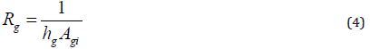
where is the gas wall thermal resistance, does represent the gas side convection resistance, represents the air-side convection, while is the air-wall thermal resistance.
Heat Transfer in the Exhaust Pipe
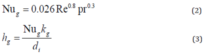
Among several heat transfer coefficient correlations for flow in a straight pipe, Seider–Tate proposed the following equation for a fully developed flow in a straight pipe. This equation, which correlates the Nusselt number with Reynold and Prandtl numbers is used to determine the gas side Nusselt number and is written as follows [14].
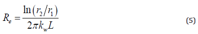
Thermal resistance of the Wall of the Exhaust Pipe
Heat is generated from exhaust pipe flow through the exhaust pipe wall. The thermal resistance at the pipe wall is removed by conduction radially through the pipe wall as follows:
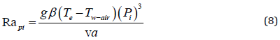
Thermal Resistance of the Air Gap
For a stationary (on test bed) exhaust system without external air flow, the mechanism of energy transfer is by natural convection in the air gap. This case is similar to a co-axial pipe with an inner pipe hotter than the outer one. The Nusselt number for the airgap is given by [15].
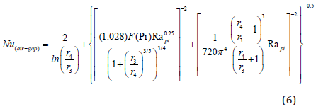
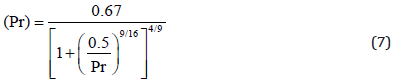
where is the function of Prandtl number in Equation 6.
where the Prandtl number function is defined as:
where is the perimeter of the inner surface of the air gap, see Figure 9.
Figure 9: Assembly of Car Heater Over Exhaust Pipe.

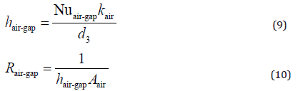
The purpose of the air gap is to reduce the heat pipe temperature lower than 200 degrees centigrade.
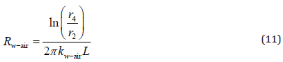
Air-Wall Thermal Resistance
The wall resistance for a cylindrical wall (air side), it is given as:
where the total heat transfer rate from exhaust gas to the working fluid is calculated using the total overall heat transfer coefficient Equation 11 and the temperature difference between the gas and air-wall side Equation 12.
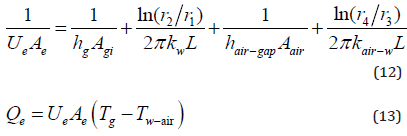
The in Equation 13 is the temperature of the outside wall of the air gap, which is almost equal to the heat pipe temperature.

Condense Section
In the following analysis, the water heat pipes are considered to be in a staggered arrangement with the aluminum herringbone wavy heat exchange. Assuming the axial heat conduction through the heat pipes walls is negligible, the following equations for steadystate operation of the heat exchanger can be written for following conditions.
Internal heat Transfer Coefficient in the Condenser Section
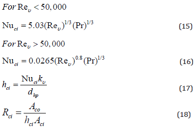
The value of the internal Nusselt Number in the condenser sections, for water vapor is calculated from reference [15] as:
Internal Heat Transfer Coefficient in the Condenser Section
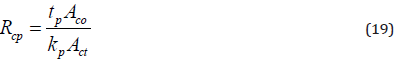
Heat transfer through the condenser wall is given by the following equation:
Thermal Resistance of Air Flow
Thermal resistance of the condenser aluminum herringbone wavy fin with circular tubing is estimated from correlations developed by Wang et al. [17] for tube diameter (Do=7.94- 9.53 mm, before expansion):
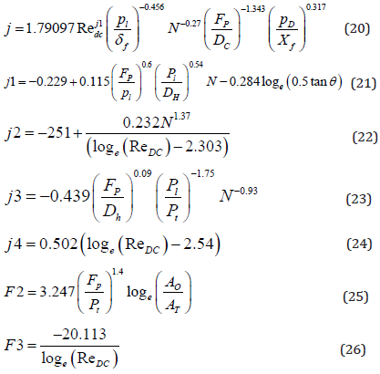
The cold side heat transfer coefficient is determined using Equation (20).

Once the heat transfer coefficients are known the overall heat transfer coefficient can be found.
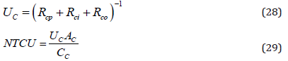
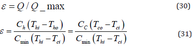
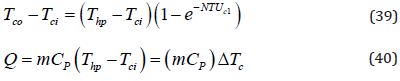
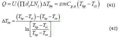
This paper describes how heat pipes can be applied in a car heater. A theoretical model based on the ε-NTU (effectiveness- Number of Transfer Units) method has been developed to predict the performance of the car heater. Effectiveness is a measure of thermal performance of a heat exchanger. It is defined for a given heat exchanger of any flow arrangement as a ratio of the actual heat transfer rate from the hot fluid to the cold fluid to the maximum possible heat transfer rate Qmax thermodynamically permitted [17].
In the condenser sections of a single row heat pipe heat exchanger, the hot fluid is in crossflow with the (vapor) flow inside the heat pipes. However since the vapor inside a heat pipe is at an almost constant temperature, its specific heat capacity, Cp, and capacity rate ratio, CL, become by definition equal to infinity, and as a result .Therefore, the effectiveness number of transfer units method (ε-NTU) equations for a single row heat pipe heat exchanger are as follows.
For the condenser section:

Now for a heat pipe heat exchanger with “n” rows of heat pipes in the direction of flow, the effectiveness-NTU equations are as follows [18].
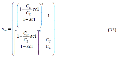
The ε-NTU method is used with an infinite heat capacity ratio due to the uniform heat pipe temperature assumption, effectiveness is found using Equation (33) [17].
For CC/CL =0, equations (33) reduces to:

The effectiveness determined through equation (30) can then be used to determine the heat transfer rate through the following expression:

The maximum heat transfer can be found by multiplying the minimum heat capacity rate by the maximum difference in temperature, which in this case is the difference between the heat pipe temperature and inlet cold air temperatures:
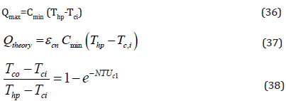
The temperature difference between the outlet air temperature and inlet cold temperature the total heat transfer rate will be written as:
Experimental Investigation
The experimental investigation was carried out using at the engine test laboratory located at the Department of Mechanical Engineering research laboratory, Iranian Research Organization for Science and Technology. The experiment was performed on the engine test bed. The heat pipe heat recovery system was located on an exhaust pipe and secured by two stainless steel hose clamps with five washers (one mm thickness each) placed to provide a small air gap (5mm) to control heat pipe temperature so as not to exceed the limit (for water heat pipe the limit is 200oC). The engine was tested by connecting K-type thermocouples at the engine’s exhaust pipe surface temperature, then the heat pipe surface temperature in the condenser section, inlet and outlet air temperature, as well as air velocity were measured across the air-cooled condenser. Another thermocouple was used to measure the laboratory environment temperature. The engine was started up and run for approximately 20 minutes to allow temperatures to settle down, (Figure 10) and at approximately 160oC data were recorded for 60 minutes [19].
Figure 10: Variation of Temperature Versus Time.

Result and Discussion
Energy recovered from exhaust gas and used to heat a minibus passenger compartment through a heat pipe was investigated experimentally and theoretically. The theoretical analysis presented in this study can be used to predict car heater performance. This paper describes how heat pipes can be applied in a car heater. The advantages of this system are as follows:
a. The system is compact,
b. independent from hot water from the engine as compared to a conventional car heater, and
c. it can be assembled or disassembled easily.
Experiments were carried out on system performance and results, presented graphically in Figure 8, show the temperatures of the exhaust pipe surface temperature (Tg), heat pipe temperature (Thp) and inlet and outlet condenser air temperature (Tco and Tci) as a function of time. From this figure, it can be observed that an increase in exhaust temperature varies sharply up to 170oC after which it increases gradually. These rises are less in heat pipe temperature and air outlet temperature and cooling air temperature remains constant. Figure 11 illustrates the variation of the heat transfer with different values of air-gap spacing ranging from 1.0 to 5.0 mm. The value of the heat transfer rate is seen to increase steadily as the gap space increases. The wall-air temperature for three temperatures ranging from 800C to 1200C are plotted. The Figure shows that the solid line (800C) with a 5.0mm. air gap is more appropriate than the other two because it can transfer additional heat allowing the system to achieve the heat pipe temperature prerequisite. Figure 12 shows the effect of the temperature difference between the heat pipe and outlet temperature of the condenser (Thp-Tco) on the energy recovered. A maximum recovered energy of 64W occurred at 380C temperature difference across the air-cooled condenser. It should be noted that the predicted recovered energy of 83W occurred at the same temperature difference. Figure 13 compares the experimental recovered energy with that predicted by the analytical model. A trend line was extrapolated from the data and the results were all situated less than 7% of the value y=0.815X+3.1405.
Figure 11: Inverted U-Tube Operation.

Figure 12: Blower with Variable Speed and Air-Cooled Condenser.

Figure 13: Experimental Recovered Energy vs Theoretical Model.

Conclusion
A car heater was designed to absorb heat from the exhaust gas and transfer it through a heat pipe to a mini-bus passenger compartment. The system was built and tested in a research laboratory and validated by a model based on the effectivenessnumber of transfer unit. The experimental results were compared with a theoretical model and the results were reasonable. One of the main outcomes of this project is that it can be beneficial to various researchers in the field of heat pipe study to control the heat pipe temperature by providing an air-gap. The heat pipe heat recovery system performance could be improved by raising the efficiency of the car heater. The recovered energy exhibits a constant upward trend as the temperature difference increases. Heat pipe heat recovery performance was also investigated experimentally for various operating conditions. Comparison of the experimental recovered energy and a theoretical model
Acknowledgment
The research presented was made possible with the financial support of the IROST. Acknowledgements are also due to my colleagues Professor L. Savadkohi head of Mechanical Engineering Department and Mrs. A. Anwari senior researcher to help me in experiment
a) Nomenclature
i. Ao - Total surface area, (m2) [W/K]
ii. C - flow stream heat capacity rate with a subscript c or h, mcp, [W/K]
iii. C*- heat capacity rate ratio, Cmin/ Cmax, [dimensionless]
iv. Cmax -maximum of Cc and Ch [W /K] [dimensionless]
v. Cmin - mssssinimum of Cc and Ch [W/K] [dimensionless]
vi. Cp- specific heat at constant pressure [J/kg K]
vii. D -pipe diameter [m]
viii. Dc - fin collar outside diameter, Do+2t_f [m]
ix. Dh - hydraulic diameter, 4AcL/Ao, [m]
x. Fp - fin pitch, [m]
xi. G - acceleration due to gravity [m/s2]
xii. h - heat transfer coefficient [W m-2 K-1]
xiii. j - St Pr1/3, (h/ (Gc_p) 〖Pr〗^ (2/3) the Colburn factor [dimensionless]
xiv. j3 - the Colburn factor for 3-row coil [dimensionless]
xv. jN - the Colburn factor for N-row coil [dimensionless]
xvi. k - fluid thermal conductivity [W/m]
xvii. mair -air mass flow rate [kg/s]
xviii. n- number of tube rows in the flow direction [dimensionless]
xix. NTU- number of exchanger heat transfer units, UA/ Cmin[dimensionless]
xx. Pe´clet - number Re.Pr, [dimensionless]
xxi. Pr -Prandtl number, (μ.C_p)/k [dimensionless]
xxii. Q - total heat transfer rate in an exchanger [W] xxiii. Ra - RayleighRa=Gr.Pr= (gρ^2 D_h^3 β^* c_p (Tw-T_m)) / μk [dimensionless]
xxiv. ReDc- Reynolds number based on tube collar diameter [dimensionless]
xxv. R - radius [m]
xxvi. Re- Reynolds number [dimensionless]
xxvii. S - gap space r3-r2 [m]
xxviii. T - Temperature, [0C]
xxix. U - overall heat transfer coefficient [W/m2 K]
b) Greek Symbols
i. α -thermal diffusivity;(m2/s)
ii. δ - gap spacing; [m]
iii. ν -kinematic viscosity [m2/s]
iv. Pr -Prandtl number ≡ν/α
v. θ - corrugation angle, degree
vi. ρ - mass density of fluid [kg m-3]
vii. μ -fluid dynamic viscosity [Ns m-2]
viii. σ- fluid kinematic viscosity μ/ρ [m^2/s]
ix. ε -Heat exchanger effectiveness [dimensionless]
x. εc - temperature effectiveness of the cold fluid [dimensionless]
c) Subscript
1. air -air side
2. c -cold-fluid side
3. g -gas side
4. h -hot-fluid side
5. i -inlet to the exchanger
6. o -outlet to the exchanger
7. w -wall or properties at the wall temperature
References
- JB Heywood (1988) Internal Combustion Engine Fundamentals, McGraw-Hill, series in mechanical engineering.
- W Strunk, EB White (2000) The Elements of Style, fourth ed, Longman, New York.
- F Yang, X Yuan, G Lin (2003) Waste heat recovery using heat pipe heat exchanger for heating automobile using exhaust gas, Journal Applied Thermal Engineering 23: 367-372.
- J Martins (2015) Thermoelectric Exhaust Energy Recovery with Temperature Control through Heat Pipes, Journal of Electronics Material 44(6): 1984-1997.
- B Orr, B Singh, L Tan, A Akbarzadeh (2014) Electricity generation from exhaust heat recovery system utilizing thermoelectric cells and heat pipes, Applied Thermal Engineering 73: 588-597.
- B Orr, A, Akbarzadeh, P Lappas (2014) Predicting the performance of a car exhaust heat recovery system that utilizes thermoelectric generators and heat pipes, in SOLAR, Melbourne, Australia.
- B Orr, A Akbarzadeh, P Lappas (2015) Reducing Automobile Co2 Emissions with an Exhaust Heat Recovery System Utilizing Thermoelectric Generators and Heat Pipes”, presented at APAC18, Melbourne, Australia.
- B Orr, A Akbarzadeh, M Mochizuki, R Singh (2016) A review of car waste heat recovery systems utilizing thermoelectric generators and heat pipes, Applied Thermal Engineering 101: 490-495.
- B Orr, Bradley, A Akbarzadeh, Experimental testing of a car exhaust heat recovery system utilizing TEGs and heat pipes, SAE-A Vehicle Technology Engineer.
- B Zohuri (2016) Heat Pipe Design and Technology: Modern Applications for Practical Thermal Management.
- DA Reay, PA Kew, RJ McGlen (2006) Heat Pipes Theory. Design and Applications (6th Edn).
- A Faghri Heat pipe Science and Technology, Taylor & Francis, Washington.
- D Chisholm (1971) The heat pipe. M& B Technical Library. TL/ME/2 Pub. Mills and Boon Ltd, London.
- JP Holman (1976) Heat Transfer (4th Edn) McGraw-Hill Book Co. New York.
- P Teertstra, MM Yovanovich, JR Culham (2005) Analytical modeling of natural convection in horizontal annuli. AIAA-2005-0959.
- AJ Chapman (1974) Het transfer (3rd Edn) Macmillan, New York.
- C Wang, JY Jang JY, NF Chiou (1999) A heat transfer and friction correlation for wavy fin-and-tube heat exchangers. Int. J Heat and Mass Transfer 42(10): 1919-24.
- E Azad, F Geoola (1984) A design procedure for gravity-assisted heat pipe heat exchanger, Heat Recovery Systems 4(2): 101-111.
- AB Green, GG Lucas (1969) Testing of Internal Combustion Engines, English Universities Press Ltd, India.


-

Mark E Smith
Bio chemistry
University of Texas Medical Branch, USA -

Lawrence A Presley
Department of Criminal Justice
Liberty University, USA -

Thomas W Miller
Department of Psychiatry
University of Kentucky, USA -

Gjumrakch Aliev
Department of Medicine
Gally International Biomedical Research & Consulting LLC, USA -

Christopher Bryant
Department of Urbanisation and Agricultural
Montreal university, USA -

Robert William Frare
Oral & Maxillofacial Pathology
New York University, USA -

Rudolph Modesto Navari
Gastroenterology and Hepatology
University of Alabama, UK -

Andrew Hague
Department of Medicine
Universities of Bradford, UK -

George Gregory Buttigieg
Maltese College of Obstetrics and Gynaecology, Europe -

Chen-Hsiung Yeh
Oncology
Circulogene Theranostics, England -
.png)
Emilio Bucio-Carrillo
Radiation Chemistry
National University of Mexico, USA -
.jpg)
Casey J Grenier
Analytical Chemistry
Wentworth Institute of Technology, USA -

Hany Atalah
Minimally Invasive Surgery
Mercer University school of Medicine, USA -

Abu-Hussein Muhamad
Pediatric Dentistry
University of Athens , Greece
