


Lupine Publishers Group
Lupine Publishers
ISSN: 2641-6921
Review Article(ISSN: 2641-6921) 
Research and Application of Steel Fiber Reinforced Concrete Lining Segments: A Review Volume 5 - Issue 3
Received:August 24, 2023; Published: September 05, 2023
*Corresponding author:Chen Ding, College of Civil and Transportation Engineering, Shenzhen University, Shenzhen 518060, China
DOI: 10.32474/MAMS.2023.05.000213
Abstract
In recent years, underground tunneling projects around the world have developed rapidly, but have been criticized by environmental organizations due to the huge carbon emissions that accompany the construction process. Meanwhile, reinforced concrete segments are prone to breakage or cracking during transportation and construction, which severely threatens the structural safety of the tunnels. Steel fiber concrete lining segment can effectively solve the above defects, the technology belongs to low-carbon construction material technology, steel fiber in improving the mechanical properties of concrete while considerably reducing the amount of reinforcement, which is conducive to energy saving and emission reduction, and also can improve the safety of the tunnel in general. Scholars from various countries have studied the deformation response law and damage key points of steel fiber concrete lining segment. The abundant research results over the years have effectively promoted the progress of tunnel construction technology and the development of current technologies. In this paper focuses on the footprint load tests, performance tests and current reinforcement forms of steel fiber concrete segments, and the article also presents current ideas and thoughts based on the existing test results of footprint models of steel fiber concrete segments.
Keywords: Shield segment, Tunnel construction; Steel fiber, Lining supports, Low-carbon building materials.
Introduction
Steel Fiber Reinforced Concrete (hereinafter referred to as SFRC) has entered the stage of gradually moving from theory to practical application due to its excellent physical and mechanical properties. The diameter or equivalent diameter of steel fiber is 0.2~0.8mm, the length is usually 15~60mm, and the L/D ratio is usually 40~100. Highly early attempts were made to test and validate the incorporation of steel fibers into the shield concrete segment pieces [1]. The steel fibers were randomly dispersed inside the concrete matrix, thus retarding the expansion of microcracks and macro cracks in the concrete matrix and enhancing the mechanical and mechanical properties such as toughness and plasticity of the concrete matrix to varying degrees [2,3]. It is noteworthy that the application of SFRC in underpass tunnel linings can also serve to reduce steel reinforcement, thereby reducing costs and carbon emissions and enhancing economic rationality and environmental benefits. It is estimated that the use of steel fibers instead of steel reinforcement in subway tunnels can reduce the combined carbon emissions by an average of about 1000 tons per kilometer in a single line [4]. This review reports the history of SFRC development and recent research on SFRC segments, especially the literature on structural loading tests on shield full-ring lining footage.
A large number of studies on steel fibers and steel fiber segments have been conducted by scholars in various countries by various means, and the research results are abundant. The popular academic papers mainly involve theoretical derivation, numerical simulation, lining footage test, in addition to many research teams cooperating with construction units to implement research work on SFRC segment with the help of metro shield project to test its practical application effect. Examples include Shenzhen rail transit line 7 [5] and Shanghai metro line 6 [6]. However, due to the high workload of conducting tests and the high requirements for equipment and sites, there are still some limitations of the current steel fiber shield segment, and there is still a large potential waiting to be explored regarding the change law and damage mechanism of the whole ring performance of steel fiber segment lining. In order to better understand steel fiber concrete and steel fiber shield segment, and to make a correct judgment on the potential innovation points and research value of fiber concrete tunnel lining structure, this paper mainly summarizes and elaborates the research results about steel fiber concrete, steel fiber shield segment and footage test in China and abroad, which is of great significance for the wide application of current sustainable low-carbon technology in tunnel engineering.
Steel Fiber Reinforced Concrete
Figure 1: Grass and clay composite building.

Concrete, the most consumed civil engineering material in the construction industry, has poor tensile and impact resistance toughness. Before the emergence of concrete, straw and mud wall buildings made from a combination of plant fibers and clay had already appeared, as shown in Figure 1. The walls of such buildings were thicker and warmer in winter and cooler in summer, and the plant fibers (straw, straw, etc.) played a great role in crack resistance reinforcement. In 1910, the American scholar H. F. Porter [7] added short steel fibers to a series of cement mortar test blocks for testing, and the results showed that the addition of steel fibers to mortar could significantly improve its tensile and compressive strength, and was the first to propose the incorporation of steel fibers to improve the tensile properties of cement concrete with the concept of tensile properties. In the 1960s, S. Goldfein first incorporated synthetic polypropylene fibers into concrete matrix as part of concrete admixtures. In 1963, Romuldi theoretically elucidated the mechanism of action of steel fibers, thus laying a solid theoretical foundation for the further research, development and wide application of SFRC, which elevated it from the minor-scale exploration experimental stage to a modern stage of large-scale development, but due to the high price of steel fibers, which primarily restricted the application of steel fibers in practical engineering. Until the late 1960s, the development of international molten steel drawing technology considerably reduced the cost and cleared the way for the large-scale application of steel fibers in engineering, and then SFRC began to be used as a modern composite building material in practical engineering in the early 1970s [8].
As shown in Figure 2 the incorporation of steel fibers in the concrete matrix is distributed in a three-dimensional disorderly manner, making it partially transformed from a brittle material to a ductile, plastic material. The experimental results published by numerous scholars [9-19] have proved that steel fibers can significantly improve the tensile strength of concrete, limit the development of cracks in concrete, and improve the ductility and plasticity of concrete through reinforcement and toughening of concrete, and the mechanism of steel fiber reinforcement is shown in Figure 3 SFRC has excellent properties such as high compressive and tensile strength, high resistance to deformation, good toughness and good corrosion resistance. Of course, the amount of steel fibers in the unit volume of concrete must be within the appropriate range, and if too many fibers are incorporated, i.e., the critical value is exceeded, the steel fibers are prone to polymerization and entanglement, staggering and agglomeration, thus negatively affecting the mechanical properties of the concrete matrix [18-19].
Figure 2: Random distribution of steel fiber in concrete test block.

Figure 3: Crack resistance mechanism of steel fiber concrete.

Research Status of Steel Fiber Shield Segment
Research on segment performance
Crack resistance
Figure 4: Mechanical analysis principle and constitutive relation of shield segment [22-23].

Cracks are known to cause highly severe damage to any concrete member, and fiber concrete shield segments offer distinct advantages precisely in terms of crack resistance. Since the behavior of its structure is somewhat different from that of conventional reinforced concrete (RC) structures, the strength of concrete-lined segments is mostly verified by footprint-lined segment flexural tests. The loading method during the test is similar to that of the flexural test for ordinary concrete beam and arch members, and the main principles of mechanical analysis and intrinsic relationships during loading of conventional curved lined segments are shown in Figure 4 Meda Alberto and his scientific team [20-23] after publishing a large number of experimental results, proposed a precast pre-reinforced concrete tunnel lining section without the use of conventional steel design and inspection method. The method can be directly used to guide the construction in the field, considering the limit and availability limit states, as well as the structural inspection of the different construction phases of the segment, including the whole process of demoulding, floor positioning, storage, transportation, handling and loading due to the ground pressure. Once the intrinsic relationship of the materials in each phase is determined, the structural inspection is performed on the lined segment by means of the moment-axial force interaction envelope of the considered limit states. According to the case study procedure of the article, the key to the method is the envelope obtained by limiting the maximum crack opening and the maximum compressive stress in the concrete.
Scholars in various countries to implement research on steel fiber concrete segment a total of the purpose is to reduce the amount of steel reinforcement, or even eventually achieve the complete replacement of steel fiber for steel reinforcement, the effect of complete replacement is shown in Figure 5. The current pressure test loading methods for shield concrete segments include single-segment loading method and angle beam loading method, as shown in Figure 6a and Figure 6b respectively, among which the angle beam loading method is more conducive to stress analysis [24] but still has limitations. GW Meng proposed a different biaxial loading method to simulate the loading state of tunnel segments, and its main test parameters are ultimate load bearing resistance value, crack pattern, reinforcement strain and member strain, and the test setup is shown in Figure 7 three full-length SFRC tunnel sections were tested using the original method and excellent results were obtained, and the results showed that the combination of steel fibers and reinforcement can delay the initial impact of cracking and increase the proportional limit of the section to make the effect enhanced. Longitudinal reinforcement in the tension region helped reduce tension strain and deflection in the mid-span section more than steel fibers. In contrast, steel fibers perform better in improving cracking load, crack resistance and toughness. The combination of fibers and steel reinforcement is the optimal choice for lined segments. Subsequently GW Meng et al. [24] also established the bending intrinsic mathematical relationship of concrete with pure steel fibers without steel reinforcement based on the properties of steel fiber material and the results of preliminary tests with the help of triangular stress blocks for compression and four-dimensional tension model. Moreover, also conducted tests for comparative verification, the data showed that the proposed σ-ε relationship can fully predict the load-deflection behavior of SFRC prisms, and the model can be used to predict and evaluate the residual bending resistance of SFRC structures.
Figure 5: Steel fibres are randomly distributed in the lining segments [30]

Figure 6: Loading method for tunnel segments [24].

Figure 7: Schematic diagram of the new biaxial loading method [22].

Figure 8: Thrust load test setup of lining segment [27]

Precast concrete lined segments are predominantly loaded using thrust jacks during the installation phase, therefore it is critical to limit cracking and damage in the segments during this phase to ensure their structural integrity and sustainability. The vast majority of scholars load precast segments considering only the member bending load capacity and thrust jacking is not considered. Mohammad Sharghi et al. addressed the limitations and conducted a study using laboratory tests, numerical simulations, analytical methods and recommended criteria, with the Tabriz Metro Line 2 project as the reference engineering case for this study. A combination of laboratory tests and Abauqs software numerical software was used to evaluate the crack resistance of fiber lined segments under the thrust of the jacking machine. Recycled recycled steel fibers can reduce the amount of spalled debris during the transportation or installation phase. Considering the CDP intrinsic model, all numerical models do not enter the plastic phase under the average thrust load (26 MN), there is no reduction in stress in this section, and the same results as in the linear elastic behavior model, none of this concrete showed damage and cracks, however, the recycled steel fibers under 80 MN thrust could not withstand the applied thrust [25]. This scholar followed up with indoor propulsion tests to monitor axial displacement, crack width, crack length and crack depth using displacement meters and image processing with good comparative results [26]. In addition Safeer Abbas, Ahmed M Soliman and Nehdi ML et al. [27-28] also considered this critical point when conducting pressure tests on tunnel steel fiber concrete segments, the site of the thrust load test is shown in Figure 8 the test results showed cracking and detachment at the bottom of the lining section. However, no cracking was observed in the UHPC lining segments made of mixed fibers, indicating stress redistribution and that the tunnel lining segments containing elevated doses of short steel fibers exhibited better crack arresting properties. Similarly, Tiberti et al. [29] investigated the possible local cracking behavior caused by the thrust action generated by TBMs and determined the positive effect of fibers in limiting splitting cracks under loading points.
Ductility and toughness
Steel fibers can withstand some of the tensile stresses to improve the tensile capacity of the matrix and absorb some of the energy in the cracking, thus giving the member a certain amount of compressive deformation capacity. Therefore, steel fiber concrete has better ductility and toughness, and its typical stress-strain relationship is shown in Figure 9. Typical compressive stress-strain curves (see Figure 10(a)) and load-displacement curves (see Figure 10(b)) for fibrous concrete tunnel lining segments are given by Moncef L. Nehdi et al. in their published paper [28]. The stress-strain curves in are horizontally shifted due to their similar initial slopes, which was done to distinguish the stress-strain curves for concrete specimens containing 0, 1%, 3%, and 6% doses of steel fibers without any overlap. The length and dosage of steel fibers had a considerable influence on the cracking tensile behavior of the members due to the crack inhibition mechanism imposed by the steel fibers. The specimens containing steel fibers showed ductile failure, exhibited a steady decrease in load-bearing capacity, and did not fracture or split into fragments at failure. On the other hand, specimens without steel fibers exhibited brittle failure and produced a loud sound at failure. The load-displacement response of the tunnel lining segment in can be divided into three stages: elastic region (part 0C in the figure), strain hardening (part CP in the figure) and strain softening stage (part PF in the figure). Initially the load-displacement curve is linear in part until the cracking point (point C in the figure). Thereafter, its slope changes, indicating a decrease in stiffness due to the development of microcracks until the peak load (point P in the figure). At the peak load, the fibers begin to develop further cracks as the stress increases. The softening phase begins with a constant shift in slope as additional fibers are pulled out or broken, along with a decrease in load carrying capacity. During the softening phase, the sound of tearing is detected as fibers are shed or broken. The failure of the structure is propagated by a single deep crack [29-30]. The cracks in the specimens were initially formed in the form of various thin microcracks, which were hardly observable to the naked eye. The crack pattern in the tunnel lining section at each stage of deformation is shown extremely graphically and accurately in Figure 11.
Figure 9: SFRC has excellent flexural toughness.

Figure 10: Deformation properties of SFRC members [28].

Figure 11: Schematic representation of cracking in UHPFRC tunnel lining segments [28].

Fire resistance
Steel fibers are inherently heat-resistant materials, and when combined with cementitious materials can mitigate aggregate shedding at ambient temperatures while facilitating the control of crack expansion when exposed to excessive temperatures, thereby enhancing the overall fire resistance of the segment. Zhi-guo Yan et al. [31] tested several samples of fiber concrete-lined segments using a newly developed facility that was able to adapt to different mechanical loads under different fire scenarios and boundary conditions. The pictures of the equipment are shown in Figure 12 and the experimental results show that the members of hybrid fiber reinforced concrete have excellent peel resistance under thermomechanical loads, while plain concrete segments have better durability. Ramoel Serafini et al. [32] proposed a mesoscale experimental procedure and used numerical methods to determine the post-fire exposure SFRC (SFRC ) bearing capacity of the tunnel lining. First, the effect of temperature on the mechanical properties of SFRC was determined by a refined experimental experiment. In addition, the applicability of the bending test and the DEWS test to evaluate the post-fire tensile properties of SFRC was verified. The variation of the SFRC bearing capacity of the tunnel with TBM technology was then evaluated using a thermodynamic model in conjunction with the example of the São Paulo metro project. The results show that the decrease in the bearing capacity is greater when the compression region of the cross-section is affected by fire. The thermodynamic model accurately estimated the variation of temperature distribution and mechanical properties with fire duration (t) and depth (z). Numerical simulations were carried out using ISO 834 and HFC software. Two scenarios with different heating rates and maximum temperatures were simulated using these fire profiles. The bearing capacity of the cross section was evaluated using the moment axis (M-N) interaction envelope method, and the results are a function of the fire curves used Figure 13 shows the M-N interaction envelope for SFRC exposed to fire after ISO 834 and HFC. Although the fire curves are different, it can be verified that the load-bearing capacity of the SFRC is significantly reduced in both cases. The load-bearing capacity of the SFRC segment decreases more rapidly when exposed to HFC, which is reasonable because HFC prescribes higher maximum temperature values and rapid heating rates during the first minutes of the fire. An attractive result is the comparable load carrying capacity of SFRC exposed to ISO 834 and HFC fire profiles when the condition tISO= 2 tHFC is satisfied (see Figure 14). Its proposed test procedure helps to classify the degree of damage suffered by the structure, to define the appropriate repair operations and to provide the designer with a procedure on the effects of fire on SFRC structures.
Figure 12: Test setup for combined mechanical and thermal loadings and support conditions [31]

Figure 13: The M − N envelopes for the SFRC exposed to fire following [32].

Figure 14: Comparison between the M − N envelopes generated as a function of the fire curve adopted [32].

Mechanical behavior of shield lining joints, joints and whole ring
In the future, China's tunnel support technology will follow the principle of "prevention first, rigid and flexible combination, multiple lines of defense, local conditions, comprehensive treatment". In the same face of pressure, the overall performance and mechanical behavior of local or single segment and lining are significantly different, so it is necessary and critical to implement the whole ring prototype loading test. The full-scale test has higher requirements for equipment and site, and the test workload is larger. The specific plan of full scale test is to simulate the pressure of surrounding rock in actual tunnel engineering with the help of multiple pressure jacking machines, steel strand, reaction wall and anchorage members, etc. The appearance of typical lying and horizontal loading test system for lining segments is shown in Figure 15. In the actual tunnel engineering, the lining structure receives the distributed load of surrounding rock. In the lying and horizontal loading test, the concentrated force applied by the jack is simulated, so that there are certain errors between the test condition and the actual situation see (Figure 16) of course, the errors are within the allowable range.
Figure 15: Schematic diagram of typical shield lining segment footprint test.

Figure 16: Difference between actual and simulated loads on the surrounding rock.

Due to the developed urban rail transit construction in Shanghai and other regions, the under-construction or constructed subway tunnels are widely distributed and of countless types, the production and operation departments are experienced in construction, and the universities and research institutes have sufficient funds, so they have the conditions to implement in-situ and full-scale tests, and there are more actual measurement data in the field [33-38]. In the future, the focus of subway shield concrete segment lining support research will be around the footprint test [39] the footprint test refers to the test object size and size of the actual object consistent with the test, can honestly and intuitively reflect the reality of the test object data test, for a different process or a different structural system, in order to obtain the basic data to guide the next step, conditions usually allow the use of the same model as the actual to implement Various working conditions of the test, this experimental model that the foot model.
Figure 17: Schematic diagram of full-scale loading test site.

Liu Xian and other scholars from Tongji University studied the stress performance of single-ring and multi-ring lining structures with straight bolt joints, bent bolt joints, and fast joint lining structures of a typical Chinese subway based on the footprint test, and obtained three important conclusions the performance of through-joint shield tunnel lining structures is determined by the performance of longitudinal joints, and increasing the ductility of longitudinal joints can change the structural damage mode from joint the performance of the staggered seam structure depends on the strength of the inter-ring interaction, and with the enhancement of the inter-ring interaction, the first plastic hinge position of the structure shifts from the longitudinal joint to the body of the tube the basic stress performance of the structure in normal operation can be optimized through the coordinated design of the inter-ring and intra-ring to improve the ultimate load carrying capacity of the structure and cause ductile damage to the structure. The team has carried out a lot of research about footage tests in recent years, and coupled with the excellent test conditions of Tongji University [40-41] the published literature has high reference value Figure 17 shows the photos of the full-ring loading test of the foot-scale lining conducted by scholars at Tongji University, where Figure 17(a) shows the picture of the specimen being loaded and Figure 17(b) shows the state of the lining ring structure after failure. Concrete segment nodes are weak parts in the lining structure, with low strength and stiffness and prone to leakage, and steel fiber concrete shield concrete segment nodes require higher ultimate load carrying capacity and crack resistance [42]. Therefore, an in-depth understanding of the actual structural behavior and damage modes of SFRC nodes in shield tunnels is necessary [43] designed and carried out structural bearing capacity footprint tests for single and staggered connection of multiple rings based on perimeter unloading, respectively. The connection types included longitudinal connections using straight bolts, bent bolts, quick sliding connectors and two types of circumferential connections. Each ring consisted of six segments, including a critical segment as shown in segment F in A Cartesian coordinate system at the center of the liner ring circle was used to represent the relative positions of the longitudinal joints, as shown in The load-displacement curves for individual liner ring samples A, B1, and C1 are shown in where the horizontal coordinate represents the ratio of the radial displacement 0-180° to the outer diameter of the ring and the vertical coordinate represents the generalized load P the dots represent the initial cracks or the concrete edges where peak stresses are reached. Since the lining structure cannot completely recover after the initial crack or the concrete edge reaches the peak stress, the dot is defined as the elastic limit. The curve from the origin to the dot represents the elastic phase of the specimen.
The square point is defined as the yield point, where the first plastic hinge occurs. Plastic hinges allow a significant increase in deformation with slight increase in load. The curve between the round and square points indicates that the specimen is in the elastic-plastic phase. The triangular point is defined as the limit. The axial forces in the single-ring specimen were matched to typical cross sections based on numerical data to derive the moment-rotation relationship for the longitudinal joints and plotted in obtaining that longitudinal joint C is fewer ductile than longitudinal joints A and B, especially in the case of negative bending moments. The non-ductile behavior of longitudinal joint C is due to a rapidly sliding connector made of brittle cast iron material, which fails suddenly under tension in the final loading phase. For the lining after the multi-ring assembly shows the load-displacement curves of specimens B1 and B2. Ring B2 is in the elastic phase when the generalized load P increases from 0 to 114.60 kN/m shows the load-displacement curves of rings B2 and C2, where ring C2 is in the elastic phase during the increase of P from 0 to 51.05 kN/m. The test results show that the single-ring failure originates from the failure of the longitudinal joint, while the multi-ring failure mostly originates from the staggering effect of the longitudinal joint and the transverse joint, and by adjusting the staggering effect, the first plastic hinge can be formed at the longitudinal joint and the segment section at the same time, so that the lining structure can reach its maximum ultimate bearing capacity.
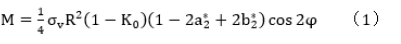
Gong CJ et al [44] studied the ultimate bearing capacity of the weak links in tunnel lining such as conventional reinforced concrete (RC) and lined segment joints under different loading conditions through full-scale tests based on the existing academic results on the structural performance of SFRC lined segment nodes, and focused on the damage process of the segment nodes, with the ultimate aim of highlighting the potential of using SFRC in tunnel applications. The ultimate aim is to highlight the potential of using SFRC in tunneling applications. It is worth noting that the authors have used a classical nodal analytical model, namely the "Geometry definition of the Einstein & Schwartz method", to implement a comparative examination of the moment capacity of the tunnel lining as shown in equations (1) and (2), and the model The four full-size segmental joint samples, named SJ1-SJ4, are shown in Table 1 shows the geotechnical parameters inputted in the article to simulate the field loading conditions of the subsurface sample caverns in Shanghai soft clay soils, and Table 2 shows the comparison between the calculated moment capacities and the experimental moment capacities. The tested bending moment capacity is obtained close to the calculated value, which illustrates the reasonableness of the Einstein and Schwartz method. The test results show that the peak load capacity of SFRC nodes is slightly higher than that of RC nodes. Compared with ordinary reinforced concrete nodes, SFRC nodes have higher initial cracking loads, adequate compression-bending ductility, equivalent initial cracking energy absorption capacity, and significantly reduced crack width. The performance-based engineering (PBE) concept is introduced to evaluate the robustness of the tested nodes, and SFRC can be an alternative to conventional reinforcement in terms of maintaining load carrying capacity and improving node and control crack control. Finally, it is verified that the classical node design method can obtain the flexural load carrying capacity of both test RC and SFRC nodes.
For the no-slip case
For the full-slip case

Table 1: Input parameters [44].

Table 2: Comparison of computed and tested bending moment capacity of the joint [83].

where M is the bending moment, φ is the angle measured counterclockwise from the right spring line, R is the tunnel radius, σv is the vertical stress, K0 is the lateral earth pressure coefficient, and , and are dimensionless coefficients. Smarslik M et al. [45] considered that the performance of tunnel lining segments is closely related to the longitudinal joint design and improved the performance of the nodes by combining high performance steel fiber concrete in the load region with conventional materials in the rest of the region, as shown in The test results obviously show the potential of mixed materials to optimize the performance of the longitudinal joints of the section lining. The superior quality material concept of using steel fiber reinforcement (HPSFRC) in the joint contact area helps the reinforcement to enter the concrete overlay, resulting in load application closer to the edge and a 15-20% increase in joint load capacity, resulting in more efficient use of the cross section. These additional load capacities can be used to reduce the lining thickness assuming constant loads and M/N ratios. At this point the joint is no longer the weakest link, but of course established practical and constructive guidelines must still be followed when carrying out concrete segment design.
Numerical simulation
Numerical simulations have also become an essential tool for conducting scientific research on steel fiber concrete segments due to the high requirements for site and test equipment and the difficulty of overall implementation for conducting full-scale tests on tunnel lining segments [46] of China Academy of Railway Sciences supported by Research and Technology Research Fund and project examples: The metro protection project of Shenzhen Qianhai Trading Square and the Qianli section project of Shenzhen Metro Line I were tested by using the single-ring full-size model of shield tunnel segment on behalf of the mechanical properties of the whole ring and the joint. The numerical model was established by using LS-DYNA and ABAQUS finite element software and combined with the full-size test results for analysis. The main results are as follows: the comparison between the numerical simulation and the full-scale test is excellent, the modeling method and parameter selection of the experimental simulation model are reasonable and reliable, which is more in line with the actual engineering situation; under the test load, the overall deformation of the segment ring presents the shape of "horizontal duck egg", with the top and bottom sunken inward and the two sides protruding outward. The joint opening of segment increases linearly before the yield of segment structure and increases rapidly after reaching the elastoplastic property point. It is the key performance point that the concrete at the camber side of the segment joint enters the elastoplastic stage when the joint is subjected to negative bending moment (the measured tension inside the segment is positive). Sun Qian et al. [47] based on the research project on the safety protection of urban rail transit engineering structure in Xuzhou City, adopted a combination of full-size test and ABAQUS numerical simulation to verify the reinforcement effect of the shield tunnel segments reinforced by internal adhesive steel plates. The results showed that: it is found that the data have a steep coincidence, which proves the rationality of the numerical model, and the mechanical parameters and displacement parameters can meet the requirements of the specification after reinforcement. In the previous numerical studies on the mechanical properties of SFRC section, the reinforcement effect of steel fiber is equivalent to the mechanical relationship of concrete, or even ignored. Similarly, the random distribution and bond - slip effect of steel fibers are not taken into account. Based on this used a three-dimensional mesoscale numerical model of the lining section of SFRC with real size to predict the crack behavior of SFRC segments. Meanwhile, with the increasingly severe energy supply situation, energy underground structures that can effectively utilize geothermal resources have gradually become a hot direction in geotechnical and underground fields in recent years, Hongzhi Cui et al [48] creatively integrated energy underground structures with steel fiber concrete segment technology, based on the characteristic that the overall thermal conductivity will be improved after the steel material is introduced into the concrete matrix, and proposed an SFRC segments to obtain shallow geothermal energy to improve the energy performance of underpass tunnels, and this author took the steel fibers into account when building the COMSOL 3D numerical model of the energy tunnel and performed a 3D time-varying thermal finite element analysis. The numerical model developed by this author is shown in represents the comparison between experimental and simulation results for the exit temperature. It can be seen that the relative error remains relatively stable (kept within 6%) when the heat exchange reaches a steady state. The final results show that the heat exchange performance of the SFRC section is significantly better than that of the plain concrete section, and in addition the authors suggest that the inlet fluid flow rate is around 0.6 m/s. The heat exchanger tube spacing was maintained between 0.5m and 0.7m. However, the research results have limitations that cannot be ignored, such as the establishment of numerical models without considering essential factors such as heat transfer between air and liner, heat transfer between liner and surrounding soil and air flow in the tunnel, and for considering complex situations such as groundwater and soil stratification Figures 18-21.
Figure 18: Segmental tunnel linings (top view): (a) Specimen A, (b) Specimen B1, (c) Specimen C1 [43].

Figure 19: Layout of tested rings in multi-ring test: (a) Multi-ring Specimen B2, (b) Multi-ring Specimen C2 [43].

Figure 20: Bending moments versus rotation angle of longitudinal joint derived from component tests [43].

Figure 21: Generalized load P versus radial displacement 0–180° obtained from full-scale ring tests [43].

Figure 22: Generalized load P versus radial displacement 0–180° obtained from multi-ring tests [43].

Figure 23: Geometry definition of the Einstein & Schwartz method [44].

Figure 24: High-performance steel fiber reinforced concrete (HPSFRC) [45].

New lining segments
Japanese scholars Ikuo Fujiki and Kyoji Oishi [49] developed a different shield concrete segment propulsion technology to accommodate rapid and long-distance construction. This segment is characterized by circular steering joints that are automatically connected only to the jack thrust of the shield machine, and these nodes are composed of concrete without using joint members, and its effectiveness was tested successively by indoor foot-scale tests, and then compared and analyzed with the construction site monitoring data, which proved that the method could meet the engineering reality. Ding Cong [50] used a modern 4D continuous end hook-shaped steel fiber to partially or totally replace the steel reinforcement with the help of the key project of the scientific research and development program of the China Railway Corporation to prepare steel fiber concrete and composite reinforced steel fiber concrete high speed railway tunnel lining segments and carried out foot-scale segment flexural tests. The results showed that the addition of steel fibers enhanced the strengthening and cracking resistance of the concrete matrix, and the strengthening and cracking resistance effect was more obvious with the increase of the length of steel fibers in a certain range of dosing, and the steel fiber concrete has strong resistance to stray current corrosion, chloride ion erosion, elevated temperature resistance and durability, which can meet the design requirements of the Wangjing tunnel segment. Based on the shield tunnel project of Shanghai Metro Line 18, Yumeng Zhang [51] and Wenyong Li [52] tested the new lining joints such as new inserted and slide-in quick connectors and after the full-ring footage test under different working conditions, they obtained that the inter-ring interaction of the new lining structure with staggered joints was stronger than that of the new lining structure with through-joints, and the convergence deformation of the new lining structure with through-joints The main conclusion is that the convergence deformation of the new lining structure is slightly larger than the value specified in the specification. Liu Xian and other scholars proposed to apply the steel plate-concrete combined structure (SPCCS reinforcement method) to the shield tunnel lining structure, and published several articles [53-54] as shown in and conducted the whole-loop full-scale static loading test to test the effect of the new structure, and the study showed that: the steel plate-concrete combined structure reinforcement method was used to Compared with the inner-tensioned steel ring reinforcement method, the steel consumption of the combined steel plate-concrete structure reinforcement method is reduced by 29.4%, while the ultimate structural bearing capacity is increased by 31.1% and the structural ductility is increased by 501% Figures 21-24.
Advances in engineering applications of steel fiber segments (in China)
Steel fiber segments have been used in a large number of rail projects in London, UK, Paris, France, Singapore, etc., and Doha, Qatar, saving a large amount of steel materials and manufacturing and installation costs, which in turn significantly reduce carbon emissions [55]. However, at present, steel fiber segments are still in the theoretical to experimental stage in China, and there is still a distance from the large-scale application. For space reasons, this paper only presents the existing cases in China, and the completed tunnel projects with field applications or trials are summarized in Table 3 it can be seen that the scale of field trials carried out in tunnels is increasing, and the length of test sections has increased from the earliest 2 m to the latest 430 m. Currently, cities such as Shenzhen are accelerating the efficiency of technological innovation and vigorously promoting the use of steel fiber concrete segment technology in underpass tunnels application. With the progress of steel fiber reinforced concrete technology and the accumulation of application experience, the technology has been gradually advanced from the research stage to the application stage in China. In 2005, Shanghai Metro Construction Company and Tongji University jointly establish a 100-meter-long tunnel test section in Binzhou Road station of Shanghai Metro Line 6, which is the earliest tunnel field test in China and has achieved positive results. This technical achievement fills the technical gap infield measurement of steel fiber concrete segments in China In 2006, Beijing Rail Transit Construction Management Co., Ltd. tried to apply hybrid fiber concrete segment technology in the shield section of "Beitucheng Station - Shaoyaju Station" of Beijing Metro Line 10 and proved that fiber concrete has obvious advantages through segment strain measurement, tunnel convergence measurement, joint mechanical effect and segment crack observation and inspection scheme [56]. In 2019, Qingdao Metro Company and China Railway Research Institute Co., Ltd. proposed and studied the technical scheme of pure steel fiber concrete segments (without reinforcement), carried out laboratory tests and field monitoring to determine the optimal group of products, and finally successfully applied in Qingdao Metro Line 1 between Ruijin Road Station and Xianjiazhai (North Railway Station) and between Beiling Station and Xiaocun Station. This is also the first time that pure steel fiber lined segment technology has been used in tunnels in China [57]. Chinese authorities compiled and issued the first national code in 2020: Fiber reinforced concrete shield Segments (GB/T 38901-2020). this standard specifies the symbol, classification, shape and specification, marking, raw materials, manufacturing process, requirements, test methods, inspection rules, marking and delivery certificate, storage and transportation of fiber reinforced concrete shield segments used in tunnel engineering. The classification of fiber concrete segments [58] with suitable reinforcement, reduced reinforcement and no reinforcement is proposed for the first time, which provides an effective guarantee for the engineering application of steel fiber shield segments.
Table 3: Application of SFRC segments in China.

Conclusion and Reflection
At present, a large number of scholars have studied the mechanical behavior and mechanical deformation characteristics of the whole ring shield segment. However, due to the elevated price of shield segment mold, segment full-size loading system and additional components, high equipment cost, complex process and prolonged test cycle. Only a few universities and research institutes with sufficient funds have loading devices and can implement full-size test research. At present, the overall test results at home and abroad are relatively few, and the existing results still have the following deficiencies:
a) The steel fiber shield concrete segment process has only been applied on a modest scale in the construction of tunneling projects in Shanghai and other areas with weak and fractured surrounding rock substrates. At present, the analysis of the damage mechanism of mechanical displacement response under complex geological environment and external load is not comprehensive, and the research work of the relevant footprint test is incomplete, and the actual construction effect of the project site needs to be further verified.
b) In terms of loading method, jack or steel strand is commonly used to load the lined segment to simulate the water pressure, soil pressure and ground resistance around the segment under specific working conditions with point and line loading, while the segment is subjected to continuous loading in the actual project; most of the existing loading systems are symmetrical loading, while the pressure around the segment is usually eccentric loading under the influence of external factors such as ground stacking, surrounding unloading and groundwater extraction, so the load applied by the loading system is slightly different from the actual working conditions.
c) In terms of device setting, most of the devices can only study the horizontally placed (lying down) concrete segment, without considering the effect of self-weight of the components and the effect of assembly on the concrete segment and joint. However, in the actual project, when the concrete segment is buried deeper and the self-weight effect is larger, this horizontal placement method will produce some differences with the actual working conditions. In addition, some loading devices only study one ring of concrete segment, ignoring the interaction force between the ring and the ring of concrete segment, and cannot consider the effect of staggered seam assembly or through seam assembly.
d) In terms of research content, the research on the mechanical behavior of the reinforced shield segment is incomplete compared with the unreinforced shield segment. In terms of the load-bearing performance of the reinforced shield segment, the reinforcement mode is single, and only the shield segment with full circle is studied, and the effects of different segment types, diameters and ring widths are not studied. However, in the actual project, the assembly method will be through-assembly or staggered assembly, and the section form can be rectangular shield section with great space utilization. Therefore, there is still a great deficiency in the research content.
e) In the lining reinforcement technology, there is a lack of research on the reinforcement effect of different reinforcement materials. At present, only composite materials and steel plate reinforcement technology are studied separately, and the optimal selection of reinforcement technology lacks a sound scientific basis. Moreover, in actual engineering, there are additional types of repair and reinforcement technologies, and the method of reinforcing damaged shield concrete segment mostly takes the combination of multiple reinforcement materials. Therefore, the concrete segment reinforcement and repair technology is still in the exploration stage, and there is an urgent need to study the influence of different reinforcement materials on the structure of the concrete segment.
f) China officially released the specification "Fiber concrete shield segment" (GB/T 38901-2020) in 2020, which provides design requirements for reduced-reinforced SFRC segment and unreinforced SFRC segment, but no scholars have yet systematically studied reduced-reinforced SFRC segment and totally unreinforced SFRC segment according to this specification.
We combine the actual situation of the tunneling project and my own thinking to make the following suggestions and outlook.
a) In terms of loading device, the current loading of the shield concrete segment by jack or steel strand is convenient and easy to implement. In order to be close to the actual working conditions, if the concrete segment is surrounded by soil and water and then loaded, it is not only difficult to operate, but also difficult to control the load around the segment, and the workload is considerably increased. Therefore, it is recommended or additional optimize the existing loading method, such as increasing the number of jacks or steel strands, or increasing the contact surface for loading. In addition, the development of devices with eccentric loading procedure can be developed to study the effect of eccentric loading on the shield concrete segment, and analyze the mechanical properties of the concrete segment structure under different hydrogeological, ground eccentric loading and pit excavation unloading conditions, so that the research results can be more accurate and facilitate the optimization of the concrete segment reinforcement.
b) In terms of loading objects, a small number of scholars have studied the standing multi-ring segment loading system to ensure the loading of vertically placed shield segments, taking the self-weight effect and assembly effect into consideration. However, due to the heavy and large size of the segment, the lack of lateral force between the rings of the segment, the assembly is more tedious, which will lose large human, material and financial resources. It is suggested that the device should be further improved to enhance the degree of intelligence and mechanization. In addition, once the standing multi-ring concrete segment is loaded to the destruction of the concrete segment, it is possible to damage the loading device, which is a difficult problem. It is suggested to consider the influence of self-weight and lateral earth pressure when studying the horizontally placed segment.
c) For the study of loading of the reinforced shield segment, the influence of through-slit assembly and staggered-slit assembly should be considered, and the shield segment with three rings and above should be loaded to further study the influence of different segment types, diameters and ring widths on the mechanical properties of the shield segment.
d) In terms of reinforcement technology, one is to increase the individual research on different reinforcement technologies, develop new technologies and optimize the traditional technologies; second is to adopt the method of combining multiple reinforcement methods to conduct tests and analyze the best combination of reinforcement methods. Third, it should be combined with the latest released codes and the actual situation of the project to conduct systematic research on reduced and reinforced fiber concrete segments to test whether steel fibers can really function as a complete substitute for steel reinforcement.
Acknowledgements
The authors gratefully acknowledge Tongji University and Shenzhen Metro for providing some of the full-scale loading test plans and device pictures.
Author contributions
All authors contribute equally to this paper. Chen Ding: Visualization, Writing - original draft, collected and analyzed data, Writing - review & editing. Xue Kaixi: Funding acquisition, Supervision. Chaohui Zhou: Investigation. All authors have agreed to the published version of the manuscript. All authors read and approved the fnal manuscript.
Funding
This research was jointly supported by the National Natural Science Foundation of China [grant numbers 42167024].
Availability of data and materials
The data and materials are included in the manuscript.
Declaration of Competing interests
The authors declare that they have no conflict of interest or financial conflicts to disclose.
References
- Sorelli L, Toutlemonde F (2005) 5570 - on the Design of Steel Fiber Reinforced Concrete Tunnel Lining Segments[C]//11th International Conference on Fracture Turin (Italy).
- Liew K, Akbar A (2020) The Recent Progress of Recycled Steel Fiber Reinforced Concrete[J]. Construction and Building Materials 232(30): 117232.
- Abbas AN, Aziz FNAA, Abdan K (2022) A State-of-the-art Review on Fibre-reinforced Geopolymer Composites[J]. Construction and Building Materials 330(2): 127187.
- LIU H Y (2022) Experimental Study and Numerical Simulation of Mechanical Properties of steel fiber reinforced Concrete [D]. Taiyuan University of Technology (in Chinese).
- Zheng Aiyuan, Liu Yingjun (2019) Study on Mechanical Properties of Steel fiber reinforced concrete Segments in Shield Tunnel Construction [J]. Transportation Science and Technology (5): 108-112 (in Chinese).
- Yan Zhiguo, Zhu Hehua, Liao Shaoming (2006) Research on mechanical properties of steel fiber reinforced concrete segments of subway tunnel [J]. Chinese Journal of Rock Mechanics and Engineering (S1): 2888-2893 (in Chinese).
- Porter HF (2017) the Preparation of Concrete-from Selection of Materials to Final Deposition [J] pp. 1910.
- Ghoneim M, Sharobim K (2020) Flexural Behavior of High-strength Fiber Reinforced Concrete Beams[J]. Aci Structural Journal 90.
- Meng S, Jiao C, Ouyang X (2022) Effect of Steel Fiber-volume Fraction and Distribution on Flexural Behavior of Ultra-high Performance Fiber Reinforced Concrete by Digital Image Correlation Technique [J]. Construction and Building Materials 320(21): 126-281.
- Li FH (2021) Performance Test of C60 Self-compacting Steel Fiber Concrete [J]. Key Engineering Materials, 871: 330-339.
- Talantova Km (2020) Steel Fiber Concrete. Constructions Terminology [J].
- Venkata siva abhilash G, Jagarapu DCK, Sai G (2016) Experimental Study on Steel Fiber Concrete [J]. Arpn Journal of Engineering and Applied Sciences.
- Zhu H, Fan X, Zhang Q (2011) Experimental Study on the Damage of Steel Fiber Reinforced Concrete By Simulation Domestic Sewage [J]. Advanced Materials Research 1801-1805.
- Rahim MA, Ghazaly ZM, Mamat RR (2016) Experimental Study of Slurry Infiltrated Fiber Reinforced Concrete [J]. Materials Science Forum 857: 363-366.
- Miao YY, Niu DT, Wang Y (2011) Steel Fiber Reinforced Concrete Carbonation Simulation Research [J]. Advanced Materials Research 108-111.
- Ju Yanzhong, Wang Dehong, Li Qiuchen (2011) Effect of steel fiber content on mechanical properties of activated powder concrete [J]. Journal of Experimental Mechanics 26(3): 254-260 (in Chinese).
- Niu Longlong, Zhang Shiping, Wei Youxin (2019) Effect of steel fiber content on mechanical properties of concrete [J]. Concrete and Cement Products (3): 51-54 (in Chinese).
- Yue Guozhu (2019) Analysis on the influence of steel fiber content on the performance of ultra-highperformance concrete [J]. Urban Road, Bridge and Flood Control (12): 199-200 (in Chinese).
- Chen Congchun, Feng Yi, Chen Xiaodong (2016) Influence of steel fiber volume content on mechanical properties of ultra-highperformance concrete [J]. New Building Materials 43(5): 54-56 (in Chinese).
- Caratelli A, Meda A,Rinaldi Z (2016) Monotonic and Cyclic Behavior of Lightweight Concrete Beams with and Without Steel Fiber Reinforcement[J]. Construction and Building Materials 122(30): 23-35.
- Di carlo F, Meda A,Rinaldi Z (2016) Design Procedure for Precast Fiber-reinforced Concrete Segments in Tunnel Lining Construction[J]. Structural Concrete 17(5): 747-759.
- Meng G, Gao B, Zhou J (2016) Experimental Investigation of the Mechanical Behavior of the Steel Fiber Reinforced Concrete Tunnel Segment[J]. Construction and Building Materials 126(15): 98-107.
- Liu X, Sun Q, Song W (2023) Structural Behavior of Reinforced Concrete Tunnel Linings with Synthetic Fibers Addition[J]. Tunnelling and Underground Space Technology 131: 104-771.
- Xu H, Wang Z, Shao Z (2020) Experimental Study on Crack Features of Steel Fiber Reinforced Concrete Tunnel Segments Subjected to Eccentric Compression [J]. Materials Today Communications 25: 101-349.
- Meng G, Wu B, Xu S (2021) Modelling and Experimental Validation of Flexural Tensile Properties of Steel Fiber Reinforced Concrete[J]. Construction and Building Materials 273: 121974.
- Sharghi M, Chakeri H, Afshin H (2021) Investigation of the Feasibility of Using Recycled Steel Fibers in Tunnel Lining Segments[J]. Tunnelling and Underground Space Technology 110: 103826.
- Abbas S, Nehdi ML (2021) Mechanical Behavior of Ultrahigh-performance Concrete Tunnel Lining Segments[J]. Materials 14(9): 2378.
- Nehdi ML, Abbas S, Soliman AM (2015) Exploratory Study of Ultra-high Performance Fiber Reinforced Concrete Tunnel Lining Segments with Varying Steel Fiber Lengths and Dosages[J]. Engineering Structures 101: 733-742.
- Tiberti G, Conforti A, Plizzari GA (2015) Precast Segments Under TBM Hydraulic Jacks: Experimental Investigation on the Local Splitting Behavior[J]. Tunnelling and Underground Space Technology 50: 438-450.
- Yang K, Yan Q, Zhang C (2021) Three-dimensional Mesoscale Numerical Study on the Mechanical Behaviors of Sfrc Tunnel Lining Segments[J]. Tunnelling and Underground Space Technology 113: 103982.
- Yan ZG, Shen Y, Zhu HH (2015) Experimental Investigation of Reinforced Concrete and Hybrid Fibre Reinforced Concrete Shield Tunnel Segments Subjected to Elevated Temperature[J]. Fire Safety Journal 71: 86-99.
- Serafini R, Dantas SRA, Agra RR (2022) Design-oriented Assessment of the Residual Post-fire Bearing Capacity of Precast Fiber Reinforced Concrete Tunnel Linings[J]. Fire Safety Journal 127: 103503.
- Zhu Min, Chen Xiangsheng, Wang Xuetao (2022) Analysis and thinking on the evolution of shield tunnel lining structure Performance [J]. Engineering Mechanics 39(3): 33-50.
- Ge Shuangshuang, Gao Wei, Wang Yiwei (2020) Research Review on the disease evaluation and Management of Traffic shield tunnel [J]. China Civil Engineering Journal pp. 1-11.
- Han Shaoyuan (2021) Review on durability of concrete lining structures in cold area tunnels [J]. Concrete and Cement Products (3): 24-27.
- Wang Jinchang, Xie Jiachong, Huang Weiming (2021) Nonlinear mechanical response analysis of shield tunnel lining [J]. Tunnel Construction (Chinese & English) 41(2): 22-35.
- Chen Xiangsheng, Li Ke, Bao Xiaohua (2021) Development overview of digital intelligent construction of urban shield tunnel [J]. Chinese Journal of Basic Science and Engineering 29(5): 1057-1074.
- Chen Xiangsheng, Xu Zhihao, Bao Xiaohua (2020) Research status overview of tunnel disease monitoring and detection technology [J]. Tunnel and Underground Engineering Disaster Control 2(3): 1-12.
- Lu Yuan (2019) Full scale Model test of Shield tunnel segment and Simulation analysis of Circumferential Joint [D]. China Academy of Railway Sciences.
- Liu Xian, Zhang Yumeng, Wang Ru Lu (2020) Discussion on deformation and failure of lining structure of subway shield tunnel [J]. Chinese Journal of Civil Engineering 53(5): 118-128.
- Liu X, Jiang Z, Mang HA (2023) Experimental Investigation of the Bearing Capacity of Deformed Segmental Tunnel Linings Strengthened By a Special Composite Structure[J]. Structure and Infrastructure Engineering 19(2): 147-163.
- Li X, Wang LG, Gao HY (2022) Experimental Investigation on Behavior of Splicing Glass Fiber-reinforced Polymer-concrete -- steel Double-skin Tubular Columns Under Axial Compression[J]. Advances in Structural Engineering 25(6): 1357-1368.
- Liu X, Zhang Y, Bao Y (2020) Full-scale Experimental Investigation on Stagger Effect of Segmental Tunnel Linings[J]. Tunnelling and Underground Space Technology102: 103-423.
- Gong C, Ding W, Mosalam KM (2017) Comparison of the Structural Behavior of Reinforced Concrete and Steel Fiber Reinforced Concrete Tunnel Segmental Joints[J]. Tunnelling and Underground Space Technology 68: 38-57.
- Smarslik M, Mark P (2019) Hybrid Reinforcement Design of Longitudinal Joints for Segmental Concrete Linings[J]. Structural Concrete 20(6): 1926-1940.
- Liu Zhao (2017) Experimental and Simulation Study on Deformation Performance of Staggered Shield Segments under Complex Working Conditions [D]. China Academy of Railway Sciences.
- Sun Qian (2021) Mechanical Properties test and numerical Simulation of Shield Tunnel segments reinforced by Internal Adhesive Steel Plate [D]. China University of Mining and Technology.
- Cui H, Li Y, Bao X (2022) Thermal Performance and Parameter Study of Steel Fiber-reinforced Concrete Segment Lining in Energy Subway Tunnels[J]. Tunnelling and Underground Space Technology 128: 104-647.
- Fujiki I, Oishi K, Saitou M (2011) Development and Construction on Automatically Constricted Segment[J]. Journal of Japan Society of Civil Engineers Ser F1 (tunnel Engineering) 67(1): 16-34.
- Ding Cong (2016) Design and Key Performance Study of Large Diameter Shield Steel Fiber Concrete Segments for high-speed Railway Tunnel [D] Southeast University.
- Zhang Yumeng, Zhang Jiaolong, Cao Weibiao (2018) Mechanical performance and design parameters of new shield tunnel lining structures [J]. Modern Tunnel Technology 55(5): 201-209.
- Li Wenyong (2018) Experimental research on design parameters of new lining structure of shield tunnel [J]. Tunnel and Rail Transit (2): 4-7.
- Liu Xian, Jiang Zijie, Liu Shuya (2020) Full scale Test of Ultimate Bearing Capacity of Shield Tunnel Lining Reinforced by Steel Plate and Concrete Composite Structure [J]. China Journal of Highway and Transport 33(1): 128-137.
- Liu X, Jiang Z, Mang HA (2023) Experimental Investigation of the Influence of the Timing of Strengthening on the Structural Behavior of Segmental Tunnel Linings[J]. Engineering Structures.
- Urban explorers of the future. Innovation story | don't need to be reinforced high performance steel fiber reinforced concrete segment.
- PU Ao (2017) Design Research and Engineering Application of Fiber Reinforced Concrete Segment [D]. Southwest Jiaotong University.
- Xu Zhen, Li Deming, Wang Bin (2020) Application of steel fiber reinforced concrete segments in hard rock tunnel [J]. Journal of Shandong University (Engineering Science) 50(5): 44-49.
- Liu Ruoyu (2018) Analysis and Research on Crack Deve Development of steel fiber reinforced concrete Segments in Subway Tunnel [D]. Southwest Jiaotong University, China.


-

Mark E Smith
Bio chemistry
University of Texas Medical Branch, USA -

Lawrence A Presley
Department of Criminal Justice
Liberty University, USA -

Thomas W Miller
Department of Psychiatry
University of Kentucky, USA -

Gjumrakch Aliev
Department of Medicine
Gally International Biomedical Research & Consulting LLC, USA -

Christopher Bryant
Department of Urbanisation and Agricultural
Montreal university, USA -

Robert William Frare
Oral & Maxillofacial Pathology
New York University, USA -

Rudolph Modesto Navari
Gastroenterology and Hepatology
University of Alabama, UK -

Andrew Hague
Department of Medicine
Universities of Bradford, UK -

George Gregory Buttigieg
Maltese College of Obstetrics and Gynaecology, Europe -

Chen-Hsiung Yeh
Oncology
Circulogene Theranostics, England -
.png)
Emilio Bucio-Carrillo
Radiation Chemistry
National University of Mexico, USA -
.jpg)
Casey J Grenier
Analytical Chemistry
Wentworth Institute of Technology, USA -

Hany Atalah
Minimally Invasive Surgery
Mercer University school of Medicine, USA -

Abu-Hussein Muhamad
Pediatric Dentistry
University of Athens , Greece
