Lupine Publishers Group
Lupine Publishers
Menu
ISSN: 2641-6921
Review Article(ISSN: 2641-6921) 
Plasma Edge Driven Magnetic Nuclear Fusion Confinement Volume 5 - Issue 1
Rahele Zadfathollah Seighalani2 and Bahman Zohuri1,3*
- 1Galaxy Advanced Engineering, A Consulting Firm, Albuquerque, USA
- 2Department of Physics, K. N. Toosi University of Technology, Iran
- 3Golden Gate University, Ageno School of Business, USA
Received:June 26, 2022; Published: July 06, 2022
*Corresponding author:Bahman Zohuri, Golden Gate University, Ageno School of Business, San Francisco, California 94105, USA
DOI: 10.32474/MAMS.2022.05.000205
Abstract
Nuclear energy driven magnetic confinement is at the verge of achieving breakeven via donut shape device known as Tokamak a toroidal apparatus for producing controlled fusion reactions in hot plasma. The Swiss team, together with colleagues at the Fusion Device ASDEX Upgrade of Germany, which operated Tokamak under Max-Plank-Institute Fur Plasmaphysik (IPP) since 1991 as part of EURO fusion’s Medium-Sized Tokamak program and Joint European Tours (JET) of United Kingdom (UK), showed that it may be possible to break Greenwald’s law of fusion (i.e., The “Greenwald’s limit is the maximum fuel density one can achieve in a Tokamak fusion device” explained by Sissinio, a member of EURO fusion’s) under conditions that can be reached in future fusion experimental devices and power plants such as International Thermonuclear Experimental Reactor (ITER). One of the main challenges facing fusion today is keeping a high-temperature, high-density plasma in the middle of a vacuum chamber and holding it there even as it reaches temperatures that are ten times hotter than in the core of the sun. This may sound impossible, and that is subject of this short technical review of present article, and it may help the fusion community to solve and overcome the problem of very hot plasma at the internal wall of Tokamak by studying the plasma edge issue. Bear in mind that reaching those temperatures hotter than core of sun in not an issue of technical problem. We can easily archive this matter by easily push a button of fusion reactor that can heat a plasma up to 150 million degrees Celsius in temperature in less than one second. However, the problem is to figure out how to efficiently control this high-energy plasma to keep it from touching the walls of the Tokamak except for the divertor, which is used as the exhaust point of the reactor and that is, where we need to take plasma edge phenomenon under consideration and that is subject of this article in general.
Keywords: Memory Metal; Plasma Edge; Nuclear Fusion Power Reactor; Tokamak Reactor; Thermonuclear Experimental Reactor; Magnetic Confinement Fusion and Very High-Temperature Environment; Hot Plasma
Introduction
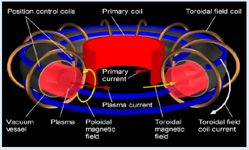
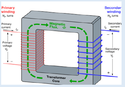
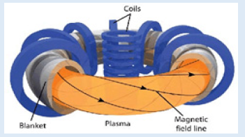
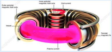
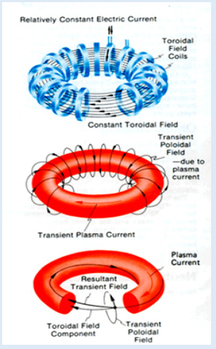
Magnetic Confinement Fusion (MCF) is an approach to generate controlled thermonuclear fusion power that uses magnetic fields to confine fusion fuel in the form of a plasma. Magnetic confinement is one of two major branches of fusion energy research, and the second one is being the inertial confinement fusion. The magnetic approach began in the 1940s and absorbed the majority of subsequent development (Figure 1). where hot plasma, magnetically confined in a Tokamak and it is subject of this short technical review. As we know, Tokamaks are toroid shaped machines that take advantage of the relation between electricity and magnetism See (Figure 2). A magnetic field creates an electric field, while an electric current creates a magnetic field. A tokamak uses multiple magnetic fields to influence the path of the plasma inside it [1,2]. From our basic college physics, we have learned that a plasma that is identified as the fourth state of matter and it is closest to a gas of the other three, but plasmas are ionized unlike normal gasses. Hence, being ionized means its particles all have either a positive or negative charge. This allows current to flow through a plasma, so it can conduct electricity. In addition, this allows plasmas to respond to electromagnetic fields as it is depicted in Figure 2, which is precisely how tokamaks confine them to a specific toroidal shape as presented in Figure 1. In current tokamaks, the current is induced in the plasma through a process known as ohmic heating. This uses the same idea as a transformer does, which is shown again in the (Figure 1).
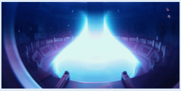
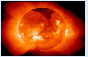
The inner loop in modern version Tokamak configuration model represents the central loop acting as a transformer. As the current runs through the plasma, it also heats it up due to the resistance of the particles present in the plasma. This current, serves multiple purposes: heating up the plasma and also inducing the current inside it so the plasma responds to electromagnetic fields (Figure 3). One source of such hot plasma that can be observed in nature, is at the surface of Sun, where natural fusion takes place as depicted in (Figure 4). This observation tells us that additional heating of plasma is required. in order for fusion to occur, first of all the plasma must be sufficiently large, and secondly heated to the temperatures of over 150 million degrees of Celsius. The ohmic heating will only heat the plasma to less than a third of this requirement, therefore other measures are needed to heat the plasma to temperatures where fusion can occur. This is driven by a technique called neutral beam injection that helps to accomplish this matter. As the plasma is ionized, only neutral particles can be entering it without being affected by the electromagnetic fields. As neutral particles are fired into the plasma, they collide with the already moving plasma particles, transferring their kinetic energy to the plasma. As it is bombarded with neutral particles, the plasma begins to heat up as energy is transferred to it accordingly. Electromagnetic waves are another form of transferring heat to the plasma. High frequency waves carry a high amount of energy and as high frequency waves are injected into the plasma, they collide with the plasma particles and transfer their energy to the plasma, further increasing the temperature. Once a high enough temperature is reached, fusion can occur.
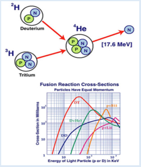
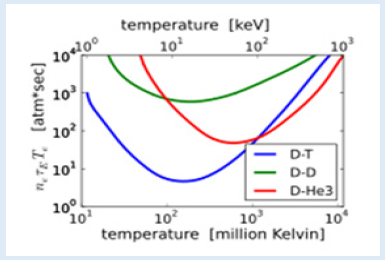
This is because a high enough temperature gives the particles enough energy to overcome the repulsive forces between the protons in their nuclei. However, this is a very strong repulsive force (i.e., Coulomb electrostatic repulsion), which is why such high temperatures are needed for the energy to overcome these forces. See (Figure 5). As we can observe in (Figure 5) fusion reactions combine light atomic nuclei such as hydrogen to form heavier ones such as helium, producing energy. To overcome the Coulomb electrostatic repulsion between the nuclei, they must reach a temperature of tens of millions of degrees, creating a plasma. In addition, the plasma must be contained at a sufficient density for a sufficient time, as specified by the Lawson criterion (triple product, (Figure 6) [2,3]. For most confinement concepts, whether inertial, mirror, or toroidal confinement, the density and temperature can be varied over a fairly wide range, but the maximum attainable pressure is a constant. When such is the case, the fusion power density is proportional to, where is the fusion Cross-Section and is the Relative Velocity, while < > denotes an average over the Maxwellian velocity distribution at the Temperature. The maximum fusion power available from a given machine is therefore reached at the temperature where is a maximum [4]. Note that, in case of Magnetic Confinement Fusion (MFC) and simple donut shape configure such as Toroidal device, we are attempting to use the electrical conductivity of the plasma to contain it through interaction with magnetic fields. (Figures 7A & 7B). The magnetic pressure offsets the plasma pressure. Developing a suitable arrangement of fields that contain the fuel without excessive turbulence or leaking is the primary challenge of this technology.
The tokamak employs many magnetic fields to ensure the plasma stays tightly confined and away from its walls. The plasma must be dense for fusion to occur, but the temperature of the plasma gets so high that anything it touches would melt instantly. This is why extremely strong magnets are needed to keep it away from the tokamak walls. Current tokamaks use two magnetic fields, a poloidal and a toroidal one. The poloidal field is created from the transformer effect and the current in the plasma itself. This field causes the plasma particles to spin in a helix pattern as it travels through the tokamak. This spinning keeps the particles constantly moving toward the center of the Toroidal field and from the walls as depicted in (Figure 8). Magnets lining the walls of the toroid shaped tokamak produce the toroidal field. Magnets wrapped around the outside of the toroid vertically produce a field that travels horizontally throughout the torus. This keeps the plasma flowing through the inside of the tokamak and keeps it away from the side walls because the field always points straight horizontally. Again, the Figure 1 illustrates this matter. Moreover, once fusion is reached and the plasma is successfully confined, the plasma will become self-sufficient. This means that no further energy needs to be added to the plasma, it can burn on its own and produce its own energy as long as more fuel is added. The fuel commonly used are isotopes of hydrogen: deuterium and tritium. Hydrogen isotopes are used because they are lighter than other elements. This means they have less protons in their nuclei, and thus have weaker repulsive forces to impede fusion. These isotopes are generally easy to find throughout the Earth, and they are also cheap. This means that after fusion is reached, the power can be produced for little cost. Power is produced through heating pads located on the walls of the tokamak.
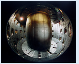
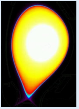
The products formed from fusion reactions will be neutral, so they won't flow with the rest of the plasma. According to ITER.ORG, about 80% of the energy released from each fusion reaction will be present in the neutron produced in the reactions. This energy is present as kinetic energy, the neutrons will be moving very fast. As neutrons are neutral, they won't be controlled by the magnetic field like the rest of the ionized plasma. Due to this, the neutrons fly out of the plasma in their initial direction at a very fast speed. As these particles hit the walls of the tokamak, they transfer their kinetic energy to heating pads, causing their temperature to increase. Water pipes are located directly next to the pads on the walls of the tokamak. As the pads heat up, the water is boiled and turned into steam. This steam then powers a turbine as is the case in most standard power plants. Tokamaks currently require a lot more money up front to build than other power sources, however they are much cheaper and safter to operate than most alternatives. The latest technology of Tokamak such as ITER configuration or Fisheye at Swiss Plasma Center (Figure 9) under construction are examining all kind of possibilities of designs. Figure 9 is presentation of Fish-eye view inside the Swiss fusion device TCV, where the experiments took place. The Figure 9 source of EPFL is from Swiss Plasma Center Fish-eye view inside the Swiss fusion device known as Tokamak à Configuration Variable (TCV). The TCV (Tokamak à Configuration Variable) is a research fusion device located in Lausanne (Switzerland). It belongs to the École Polytechnique Fédérale de Lausanne.
Research
The EFPL's research domains at the TCV comprise various topic areas. For instance, researchers focus on the development of new plasma shapes, the heating of plasma using ECRH as well as research question from the topic area of transport and rotation. Furthermore, they deal with research objectives regarding H-mode and advanced Tokamak scenarios. You can find further information and more research areas on the website of the EPFL.
Note That: Electron Cyclotron Resonance Heating (ECRH) launches microwave beams of the same frequency as the electrons move on corkscrew like paths around the magnetic field lines. These resonant microwaves are absorbed by the electrons and the plasma heats up.
ECRH is a very precise and powerful heating tool: As the cyclotron frequency depends on the magnetic field, which itself is a function of the location, the heating energy may be deposited at selected locations, thus tailoring the temperature profile in the plasma. Moreover, if the microwave beams are launched under an oblique angle with respect to the field-lines – e. g. by means of mirrors – local currents may be driven modifying themselves the confining magnetic field. ECRH is the main heating system of Wendel stein 7-X and the only one which is already by now capable to operate continuously. For Wendel stein 7-X high power microwave sources – so called gyrotrons – were developed under the auspices of the Karlsruhe Institute of Technology (KIT). Each gyrotron is capable to provide nearly 1 MW heating power over 30 minutes. The development of 1.5 MW units is being prepared. Ultimately, up to 12 of these microwave sources will be installed with their periphery in the ECRH-building providing a total power of up to 15 MW to heat the plasma [5]. For the second campaign (OP1.2) 10 gyrotrons were available and provided a maximum power of about 7.5 MW to the plasma. See (Figure 10)
Figure 10: ECRH System of Wendelstein 7-X showing one of Two Transmission Lines between the Gyrotrons (right) and the Wendelstein 7-X Torus (left).
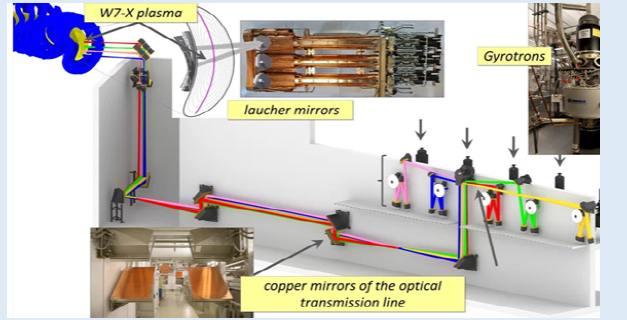
The magnetic field of Wendel stein 7-X with 2.5 Tesla on the plasma axis requires a microwave frequency of 140 GHz corresponding to a wavelength of about 2 mm. Whereas most experiments use waveguide technology for these frequencies for Wendel stein 7-X a quasi-optical transmission line was developed together with the University of Stuttgart. This transmission line guides the beams over about 60 m from the gyrotrons to the plasma with copper mirrors. Due to the high steady- state power these mirrors need to be cooled. In fact, on the other hand the microwave beams propagate in air with practically no losses that allows to keep gyrotrons and their periphery distant from the torus building, which is advantageous particularly for future large devices, if they are going to be built.
Technical Data
1. Major plasma radius: 0.89 meters
2. Minor plasma radius: 0.25 meters
3. Aspect ratio: 3.5
4. Plasma elongation: 0.9 − 2.8
5. Plasma triangularity: -0.8 − +0.9
6. Maximal plasma current: 1.2 MA
7. discharge duration: 2.6s in ohmic, 4s with ECCD
8. Core electron density: 1−20×1019 m-3.
9. Core electron temperature: ≤ 1 keV (ohmic), ≤ 15 keV (ECH)
10. Core ion temperature: ≤ 1 keV
11. Main ion component: deuterium, hydrogen or helium
12. Main heavy impurity: carbon (C⁶⁺).
Its particularity is that its torus section is three times higher than wide. This allows studying several shapes of plasmas, which is particularly relevant since the shape of the plasma has links to the performance of the reactor. The TCV was set up in November 1992. In summary, the Tokamak à configuration variable ("variable configuration tokamak", TCV) is a research fusion reactor (tokamak) of the École polytechnique fédérale de Lausanne.
A Revision of Fundamental Law for Tokamak Fusion Energy (Greenwald’s Law)
A revision of a fundamental law for tokamak fusion energy has doubled the fuel potential, thereby increasing the output energy potential. The revision to the so-called Greenwald’s law – after fusion scientist Martin Greenwald – which has been foundational to fusion research and tokamak development for over three decades, suggests that the amount of hydrogen fuel that can be injected into the tokamak can be increased almost two-fold, enabling operation at a higher power level. Greenwald’s law correlates the fuel density to the radius of the toroidal shaped tokamak’s inner circle and the current that flows in the plasma inside the tokamak and sets a limit on its operation. With increasing fuel density, at some point a ‘disruption’ occurs, in which the confinement of the plasma is lost, and the fusion process breaks down. Greenwald’s law was used in for example the design of the forthcoming International Thermonuclear Experimental Reactor (ITER) tokamak, which now should be able to operate at a near doubled fuel density and generate more fusion energy than previously thought.
“One of the limitations in making plasma inside a tokamak is the amount of hydrogen fuel you can inject into it,” says Paolo Ricci, a physicist at the EPFL Swiss Plasma Centre in Lausanne, who led the research. “The finding is important, just because it shows that the density that you can achieve in a tokamak increases with the power you need to run it. Actually, DEMO will operate at a much higher power than present tokamaks and ITER, which means that you can add more fuel density without limiting the output, in contrast to the Greenwald law. And that is very good news”. The finding was based on experiments using sophisticated technology to precisely control the amount of fuel injected into a tokamak, which were conducted at the Joint European Torus (JET) in the UK, at the ASDEX Upgrade in Germany and EPFL’s own TCV tokamak. Alongside this, theoretical analysis was undertaken of the physical processes that limit the density in tokamaks. Computer simulations showed that as more fuel is added into the plasma, parts of it move from the outer cold layer of the tokamak, the boundary, back into its core, because the plasma becomes more turbulent. This in turn causes it to cool down, making it more difficult for the current to flow and possibly leading to a disruption uses magnetic fields to confine fusion fuel in the form of a plasma. Magnetic confinement is one of two major branches of fusion energy research, along with Inertial Confinement Fusion (ICF) as the second option for plasma driven fusion. The magnetic approach began in the 1940s and absorbed the majority of subsequent development. See (Figure 3) where hot plasma, magnetically confined in a Tokamak and it is subject of this short technical review.
In summary, as we have stated before as “breaking a law of fusion” definition, future devices such as Tokamak may be able to reach a higher fuel density and energy performance than what was predicted by fusion’s “Greenwald Limit”, which if we overcome this limitation, then researchers of MCF think that future devices may be able to operate way beyond the field’s iron-clad of this limit of how much fusion fuel or plasma they can handle before losing control. With also implementation of nanotechnology driving nanomaterials, thus “Memory Metal or Shape Memory Alloy”, future innovation of MCF is by far out seems very promising [4-6]. Furthermore, as it was stated “Greenwald’s limit is the maximum fuel density one can archive in a “Tokamak Fusion Device” and from plasma physics point of view it is described as follows.
The Greenwald limit is an operational limit for the density in magnetic confinement devices [7]

where is the line average density in 1020 1/m3, is the plasma current in mA and is the mirror radius in unit of meter.
In tokamaks (and Reversed Field Pinches [8] exceeding the Greenwald limit typically leads to a disruption, although sometimes the limit can be crossed without deleterious effects (especially with peaked density profiles). Stellarators can typically exceed the Greenwald limit by factors of 2 to 5, or more (replacing by an equivalent current corresponding to the magnetic field).
The mechanism behind this phenomenological limit is not fully understood, but probably associated with edge gradient limits. Recently, an explanation based on the formation of magnetic islands was proposed [9]. Bear in mind that this limit is in addition to the operational limits imposed by Magneto-Hydro-Dynamic (MHD) stability on plasma current and pressure, and it is an independent limit on plasma density is observed in confined toroidal plasmas. Perhaps the most surprising result is that all of the toroidal confinement devices considered operate in similar ranges of (suitably normalized) densities. The empirical Scaling’s derived independently for tokamaks and reversed-field pinches are essentially identical, while stellarators appear to operate at somewhat higher densities with a different scaling [9]. In tokamaks, where the most extensive studies have been conducted, there is strong evidence linking the limit to physics near the plasma boundary: thus, it is possible to extend the operational range for line-averaged density by operating with peaked density profiles. Additional particles in the plasma core apparently have no effect on density limit physics. Fusion scientist Martin Greenwald derived the empirical limit in 1988 from observations at small experimental devices, not theory. His limit sets a ceiling on the achievable plasma density – and thus the maximum fusion power - in any fusion device.
The Plasma Edge Facing Fusion Driven Magnetic Confinement
So far, we have learned enough detailed about old technology involved in Tokamak and its innovative version of it ITER, and now are at the stage that we can describe technology and what is involved with understanding of “Plasma Edge”. For that we need to have understanding of Plasma – Wall Interaction (e.g., Surface Erosion) within Tokamak and consequently ITER as well. The first material surface facing the plasma has incident upon it a variety of particle and energy fluxes. However, while we have learned about Magnetic Confinement Fusion (MFC), by now we know that the magnetic confinements are not yet to their ultimate perfection level and still there are fluxes of charged particles – electrons, plasma ions, alpha particles from the fusion reaction, impurity ions that have been previously eroded from the surface, and ions from the Neutral Beam Injunction (NBI) process [10].
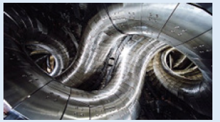
Note that: Neutral-beam injection (NBI) is one method used to heat plasma inside a fusion device consisting in a beam of high-energy neutral particles that can enter the magnetic confinement field. When these neutral particles are ionized by collision with the plasma particles, they are kept in the plasma by the confining magnetic field and can transfer most of their energy by further collisions with the plasma. By tangential injection in the torus, neutral beams also provide momentum to the plasma and current drive, one essential feature for long pulses of burning plasmas. Neutral-beam injection is a flexible and reliable technique, which has been the main heating system on a large variety of fusion devices. To date, all NBI systems were based on positive precursor ion beams (Figure 11). In the 1990s there has been impressive progress in negative ion sources and accelerators with the construction of multi-megawatt negative-ion-based NBI systems at Large Helical Device (LHD) (Figure 12) (H0, 180 keV) and JT-60U (D0, 500 keV). The NBI designed for ITER is a substantial challenge [11] (D0, 1 MeV, 40 A) and a prototype is being constructed to optimize its performance in view of the ITER future operations. [12] Other ways to heat plasma for nuclear fusion include Radio Frequency (RF) heating, Electron Cyclotron Resonance Heating (ECRH), Ion Cyclotron Resonance Heating (ICRH), and Lower Hybrid Resonance Heating (LHRH). Using Figure 11, the mechanism of NBI, typically is done as:
Making a plasma: This can be done by microwaving a low-pressure gas.
Electrostatic ion acceleration: This is done dropping the positively charged ions towards negative plates. As the ions fall, the electric field does work on them, heating them to fusion temperatures.
Re-neutralizing: The hot plasma by adding in the opposite charge. This gives the fast-moving beam with no charge.
Injecting: The fast-moving hot neutral beam in the machine.
It is critical to inject neutral material into plasma, because if it is charged, it can start harmful plasma instabilities. Most fusion devices inject isotopes of hydrogen, such as pure deuterium or a mix of deuterium and tritium. This material becomes part of the fusion plasma. It also transfers its energy into the existing plasma within the machine. This hot stream of material should raise the overall temperature. Although the beam has no electrostatic charge when it enters, as it passes through the plasma, the atoms are ionized. This happens because the beam bounces off ions already in the plasma Bear in mind that, the Large Helical Device (Ōgata Herikaru Sōchi) (LHD) is a fusion research device in Toki, Gifu, Japan, belonging to the National Institute for Fusion Science. It is the second largest superconducting stellarator in the world, after the Wendel stein 7-X. Return tour subject of plasma – Wall Interaction, thus “Surface Erosion”, most of the plasma ions recycle from the wall as “cool” neutral atoms, and some of these undergo charge-exchange with plasma ions, creating thereby a flux of energetic “charge-exchange neutrals” incident upon the surface.
The magnitude of the charged particle flux can be estimated from:

where is the average density, is the particle confinement time, volume refers to the plasma, and area refers to the wall. More details can be found in book written by W. M. Stacey [10]. Reference [10] Chapter-6, Section 6.1, calculations and extrapolation of present experimental results indicate that the most probable energy of particles emanating from the edge of a tokamak reactor plasma will be in the range of ~100–300 eV. However, radiative cooling of the plasma edge by wall-eroded impurities may act to reduce the edge temperature without adversely affecting the plasma center if a medium-z impurity (e.g., stainless-steel) which becomes entirely ionized at the central plasma temperatures is used. Whether such a “cold, radiating edge” condition will be stable remains an open question. Bear in mind that, Insulating the plasma from the wall by interposing a region of high-density “cold” neutral gas has also been suggested as a means of reducing the energy of the particle fluxes striking the wall to below the sputtering threshold. All the above discussion is part of “Impurity Control” innovative technique, which refers to those techniques that are employed to maintain the plasma purity within acceptable limits by preventing wall-eroded atoms from entering the plasma and/or by exhausting wall-eroded or fusion product ions from the plasma. This issue has been studied extensively for tokamaks.
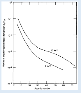
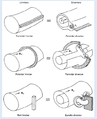
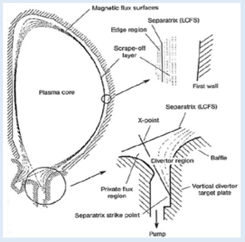
Conceptually the simplest solution to the wall-eroded impurity problem is to prevent the erosion from taking place. Since it is practically impossible to eliminate the particle fluxes emanating from the plasma, prevention of erosion can only be accomplished by reducing the energy of these particles below the threshold energy for sputtering. This threshold energy varies from a few electron volts for the low-z materials to a few hundred electron volts for the high-z materials, as discussed in Stacy book [10] and illustrated in Figure 13, where the maximum permissible impurity concentration is plotted. It is apparent that only miniscule quantities of intermediate- and high-z impurities can be tolerated in a plasma. Thus, there is clearly a need for some means of preventing the impurity ions that are sputtered from the first wall surface from entering the plasma. Calculations indicate that the thickness of such a “gas blanket” would have to be so great (~1 m) as to make it impractical. Perhaps the next simplest solution to the wall-eroded impurity problem is to mitigate the adverse effects of radiative cooling by using a low-z wall surface. Reference to Figure 13 shows that concentrations up to ~10% of low-z impurities may be tolerable in a plasma. As of today, the most successful technique that has been implemented, involves magnetic diversion of the particle fluxes emanating from the plasma into a separate chamber. The principle, which is illustrated in Figure 14 is to divert some or all of the magnetic field lines near the walls of the plasma chamber out of the plasma chamber into a separate divertor chamber. The charged particles approaching the wall are then swept out of the plasma chamber into a divertor chamber where they are finally incident upon a divertor collector plate. A representative poloidal divertor configuration for a Tokamak is shown in (Figure 15) and Figure 16.
A fraction of the particles reflected from the divertor collector plate are pumped out a vacuum duct, and the remainder remain in the divertor chamber as a cold partially ionized gas which serves to insulate the collector plate from the plasma by cooling the particle fluxes from the plasma as they pass through. Impurity atoms eroded from the collector plate are impeded from returning to the plasma chamber by this high-density gas and by the divertor action itself once they become ionized [10]. Divertor experiments have demonstrated conclusively that the impurity content of a plasma can be significantly reduced by magnetic divertors. For reasons that are not entirely understood, the magnetic configuration associated with the divertor also leads to improved energy confinement, altogether independent of the effect on plasma purity. The principal disadvantage of the divertor is that the required magnetic coil systems are complicated and expensive when extrapolated to a reactor.
According to W. M. Stacey book [10], an alternative to the divertor is to use a material “limiter” in the plasma chamber, as illustrated in Figure 14 here and it is depicted in his book as well. Particles reaching the edge of the plasma chamber strike the limiter, where they are reflected as neutrals and also cause sputtering of the limiter. If a vacuum pumping duct is located so that a significant fraction of the neutral particles reflected and sputtered from the limiter can be pumped out of the plasma chamber, then the limiter can be utilized as a mechanism for removing impurities from the plasma. The erosion of the limiter can be a major impurity problem, because of the proximity to the plasma, unless the edge of the plasma can be cooled (radiatively) sufficiently that the particle fluxes are incident on the limiter with energies below the sputtering threshold.
Figure 18: Illustration of Pressure Gradients along the Edge Region, a) High Confinement = Good Insulation, b) Low Confinement = Bad Insulation
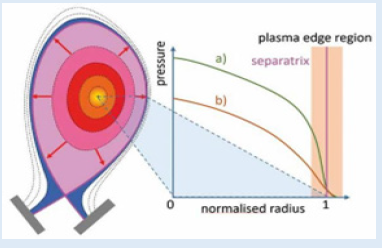
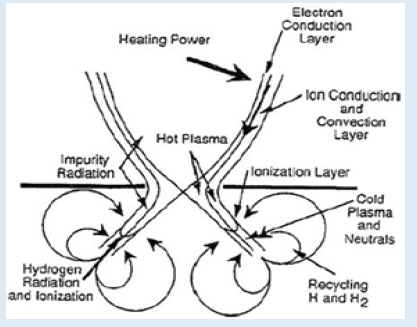
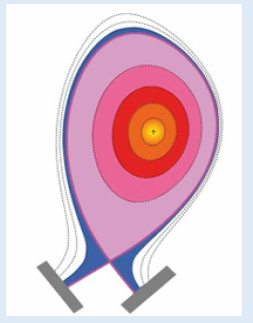
A more realistic depiction of a divertor configuration is given in Figure 15, and Figure16 shows the many processes that go on in the divertor. Furthermore, mechanism employed to control the plasma edge region (e.g., limiters, divertors) tend to concentrate these particle and heat fluxes in localized areas. Special components are required to handle these concentrated heat and particle fluxes. In summary, we can take Figure 15 and Figure 16 into consideration and make a simplified version of them as illustrated in Figure 17 here, where it shows a cross-section of a plasma-filled Tokamak with a divertor as presented in form of two grey color bras at the bottom and they called a “Magnetic Field Configuration (MFC)”, and it is basically the same for any Tokamak. In (Figure 17). The dashed lines represent magnetic flux surfaces. The purple line is the separatrix and the region at the bottom, where the field lines are touching the wall (the two grey plates), is called divertor.
The dotted lines represent magnetic flux surfaces. Although only eight are shown in this picture, in reality there is an infinite number of these magnetic layers sitting within each other (we often use the term “nested”) just like layers in an onion. Since the plasma consists of charged particles, we can control it with these magnetic fields. The particles can move rapidly along one magnetic flux surface (layer), but only very slowly from one layer to another – in other words, they are magnetically confined. The confined region of the plasma is where the magnetic flux surfaces are “closed” like a ring. Further out are the “open” layers that touch the divertor. We call this region the scrape-off layer. The last closed magnetic flux surface, called the separatrix (the purple line in Figure 17), separates the confined region of the plasma from the scrape-off layer. The area that interests me is the general region surrounding the separatrix. We call it the plasma edge region (the pink, purple and blue sections shown in (Figure 17)).
The Importance of the Plasma Edge
With a size of only a few centimeters, in contrast to a total plasma radius of 2 meters in the ITER tokamak, the plasma edge region is very small compared to the overall plasma size - like an eggshell compared to the egg. Despite the fact that the desired fusion reactions do not occur in this region, this area plays a key role in realizing fusion on earth, because the processes that do occur within it are of major importance for 1) the overall behavior of the plasma and 2) the power exhaust process. The first important role of the plasma edge region is to set the boundary for the hot core plasma in the confined region (the yellow, orange and red regions in Figure 17). It surrounds the burning plasma and acts like a shield between it and the reactor walls. In the plasma edge region, the gradients (changes in a given direction) of temperature and density are very steep – i.e., the properties change fast over the radius. The combination of the width of this layer and its gradient defines the boundary to the plasma core. We have found that the higher the core boundary temperature is, the better the conditions will be for fusion to occur in the plasma core. Think of the plasma edge region as the insulated outer walls of a heated house. With no insulation and open windows, the heat flows right through the walls. In this case, the temperature gradients in the outer wall region are low. If we close the windows and insulate the walls, the temperature in the wall region – from just inside the house to just outside the house – changes from high to low over a very short distance. The temperature gradient is now steep. So, we can say that the higher the temperature difference at constant heating, the more efficient the thermal insulation of the house. Back in a Tokamak, the insulating properties of the plasma edge region can be explained by transport barriers which can build up just inside the separatrix in the confined region. The better this barrier, the higher the temperature difference and thus the higher temperature and density will be at the plasma core – which makes it more likely that fusion will occur successfully.
Note that: The Separatrix is the boundary separating magnetic field lines that intersect the wall (open lines) and the closed magnetic field lines that never intersect the wall (closed lines). Defines the plasma edge.
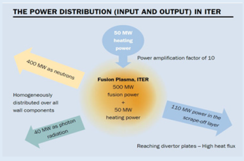
The second role of the plasma edge region is to moderate the power distribution in the scrape-off layer and the divertor heat loads. This is still a key nuclear fusion research challenge because the amount of power we are talking about is enormous! The steady-state operation of a nuclear fusion device is the ultimate goal for an efficient fusion power plant. That means keeping plasma parameters like temperature and density, as well as the fusion power produced, constant over time. To sustain and control the fusion process, continuous external heating is necessary. For ITER the foreseen heating power is 50 megawatts - the power equivalent of 500 car engines or 25.000 hair dryers. Moreover, the desired goal for ITER is to use this 50 megawatts heating power to generate 500 megawatts of power released by the resulting fusion, which corresponds to a power amplification factor of Q = 10. Because we do not want the machine to continuously heat up, the challenge becomes removing the 550 megawatts (50 megawatts heating plus 500 megawatts fusion power) from the tokamak chamber. This means: What goes in has to go out. But the question is, how can we remove power from a nuclear fusion device? 80% of the fusion power (400 megawatts) is carried by the fusion neutrons. As they are electrically neutral, they do not interact with the magnetic field cage and are therefore distributed evenly over all wall components. The same holds true for the generated photons (light emitted by the plasma), which carry a total power of 40 megawatts to the wall. These two parts are not the problem. Heat exchangers placed behind the first wall use them to generate electrical power.
The challenge is handling the remaining 110 megawatts of power, carried by charged particles that slowly move from the hot core to the relatively cooler plasma edge. Physicists call this process diffusion. Once the particles cross the separatrix and reach the scrape-off layer, they are transported to the divertor. Due to diffusion, some charged particles reach more outward layers before touching the divertor. The speed of this diffusive outward motion influences the width of the blue area in Figure 17, which is a belt roughly three centimeters wide surrounding the divertor. If all the power in the scrape-off layer was deposited in this tiny region, we would end up with a power density (amount of power per area) of 100 megawatts/square meter. No material can withstand these power loads, as it is higher than if we placed the material directly on the surface of the sun! [4,6].
This means we have to minimize these power loads somehow. To manage this, we combine two strategies. First, we must get rid of some of the power in the scrape-off layer by additional radiation (plasma has to emit additional light, which is again homogeneously (equally) distributed over all the machine components). Second, we must increase the area in the divertor reached by the particles. Heat-carrying filaments, which occur in plasma, can help us do this. Filaments are structuring several meters in length, which stretch along the field lines. In the cross-section, they appear as a small dot of only a few millimeters in diameter. Comparable to flares in the sun (Figure 18) they can carry temperature and density radially outwards, speeding up the slower diffusive outward transport of heated plasma particles. In contrast to diffusion, where heat is transferred between particles, heat transported by the filaments is due to the movement of the particles themselves. We call this process “convection”. It is the same physical principal as when you use your convection oven, which uses a fan to move the hot air particles around. To be able to control these filaments through plasma shaping, fueling, and heating, we need good experimental access to the underlying physics. In other words: we need to conduct experiments to better understand the physics of these filaments and how we can control or at least influence them.
Diagnostic Access
The filaments are turbulence-driven and can move radially outwards with velocities of several kilometers per second. Diagnostic instruments that measure parameters like the temperature and density of plasmas therefore have to deliver a sufficient temporal and spatial resolution (be very quick and able to record all points in the diagnosed area). See (Figure 19). In fact, they record one million frames per second to catch these filaments! This is so fast that watching two seconds of a recorded plasma discharge at the standard television framerate of 24 frames per second would take around 22.5 hours -- the same as watching all the Star Wars movies back-to-back. This would take too long, so we use atomized and statistic-based analysis tools to catch the occurrence of filaments. Someday, we hope that these powerful diagnostics, combined with enhanced theoretical models and improvements in materials, will help us control even the hottest of plasmas and harvest the heat energy created by fusion reactions in future devices like ITER and DEMO (Figure 20). Controlled fusion for electricity production was promised by scientists a long time ago. But now we can see how all the parts are coming together and how the remaining problems are being identified and addressed one after another. we find it so interesting and rewarding to get to work on solving one of the pieces needed to realize the promise and make fusion happen within our generation – the ITER generation. in bottom line, Tokamak plasmas in ITER and other future reactors need the effective energy confinement of the so-called H-mode to maintain high temperatures in the core. H-mode has a self-generated insulating layer in the plasma edge. The energy confinement provided by this layer is good enough that the outflowing energy piles up until an instability known as the Edge Localized Mode (ELM) occurs. The challenge is to retain the layer’s excellent energy confinement while preventing the ELMs. The QH-mode operates naturally with sufficient additional turbulent edge energy transport to eliminate the ELMs while retaining excellent energy confinement in the plasma core. The elegant feature of QH-mode is that the plasma generates this edge turbulence modification by itself. When first discovered, QH-mode was created using rapid plasma rotation driven by torque injected using the neutral hydrogen heating beams. However, the effective torque in much larger future machines will be too small to produce enough rotation. Recent experiments on DIII-D National Fusion Facility created and sustained a variant of QH-mode (wide pedestal QH-mode) using no net neutral beam torque. As a bonus, the wide pedestal feature improves edge stability, allowing operation at higher edge plasma pressure by widening the pedestal, even though the local temperature and density gradients decrease [7-12].
Conclusion
In conclusion, Plasma Edge is starting with the measure losses of particle and heat from the confinement devices for fusion are observed to be larger than predictions from theories based on inter-particle collisions. The discrepancy is believed to be due to transport governed by highly non-linear turbulent processes, occurring on multiple spatiotemporal scales, driven by different energy sources, mainly the inhomogeneity of plasma pressure profiles and confining magnetic field, and with a number of regulating mechanisms. Since good confinement is necessary to achieve self-sustained, energy producing plasmas, understanding, controlling, and predicting turbulent transport across a wide variety of plasma conditions is an issue of crucial importance. In particular, understanding turbulence in the edge of magnetic confinement device is an outstanding open issue in magnetic fusion. In this region, plasma interacts with the solid wall of the device, determining the boundary conditions for the core plasma, and controlling the plasma refueling, heat losses, and impurity dynamics.
The study of edge turbulence is quite challenging. First, a very wide range of spatiotemporal scales is involved and a number of approximations that are used in the study of the core plasma (e.g., small amplitude fluctuations) are not valid. The edge magnetic geometry is also particularly demanding, being constituted by a closed flux surface region, and by the Scrape-off-Layer (SOL) region, which extends outside the last closed flux surface and is characterized by open magnetic field lines ending on the tokamak limiter or divertor. Moreover, different turbulence regimes are observed in the edge. In particular, when the plasma is heated above a characteristic power threshold that depends, principally, on the plasma density, magnetic field amplitude, plasma configuration, and machine dimensions, turbulence is suppressed, and a characteristic sharp temperature gradient forms, the so-called edge pedestal, associated with the presence of a transport barrier. The transport barrier causes an increase of the plasma confinement time and leads to a transition from a low to a high mode (H-mode) confinement regime, the so-called L-H transition. A key characteristic of these transport barriers is the presence of a localized, non-uniform electric field with associated cross-field flow shear. The H-mode pedestal can be subject to Edge Localized Modes (ELMs) that impact the global confinement and fusion performances and induce transient heat load on the tokamak first wall, constraining its lifetime.
Note that: Edge Localized Modes, ELMs for short, are one of the disturbances of the plasma confinement that are caused by the interaction between the charged plasma particles and the confining magnetic field cage. During ELM events, the edge plasma loses its confinement for a short time and periodically throws plasma particles and energy outwards onto the vessel walls. Typically, one tenth of the total energy content can thus be ejected abruptly. While the present generation of medium-sized fusion devices can cope with this, large devices such as ITER or a future power plant would not be able to withstand this strain. Experimental methods to attenuate, suppress or avoid ELMs have already been successfully developed in current fusion devices. The ELM instability builds up after a quiet phase of about 5 to 20 milliseconds—depending on the external conditions—until in half a millisecond between 5 and 15 percent of the energy stored in the plasma is flung onto the walls. Then the equilibrium is restored until the next ELM eruption follows. Although the success of ITER will critically depend on achieving the H-mode regime and controlling its stability, the theoretical understanding of the transition to it and its dynamics, in particular the ELM physics, are still an open issue.
Leveraging on the unique possibilities offered by SPC, in particular the availability of a set of state-of-the-art numerical codes, the tokamak TCV, and the basic plasma physics experiment TORPEX, we are approaching the study of plasma edge turbulence, with the goal of contributing to the achievement of a viable design for a thermonuclear fusion reactor. Finally, in this Short Technical Review, we have just gathered separated information among technical textbooks and loose article that we have come crossed and brough under one umbrella for graduate students and engineers fresh out of graduate college that are in business plasma physics and Magnetic Confinement Fusion (MCF) and involved with Tokamak machine and now its advanced version ITER if they are anxious to gather more information and knowledge. We hope this assembly helps them to understand the subject of “Plasma Edge” better.
References
- Zohuri B (2016) “Plasma Physics and Controlled Thermonuclear Reactions Drive Fusion Energy”, 1st Edition, Springer Publishing Company.
- Zohuri B (2016) “Magnetic Confinement Fusion Driven Thermonuclear Energy”, 1st Edition, Springer Publishing Company.
- World Highest Fusion Triple Product Marked in High-βp H-mode Plasmas Archived 2013-01-06 at the Wayback Machine.
- Zadfathollah R, Seighalani, Zohuri B (2022) “Nanomaterials Drive Magnetic Nuclear Fusion Confinement Approaches, (A Technical Memorandum)” Journal of Energy and Power Engineering 16: 91-113 doi: 10.17265/1934-8975/2022.03.001
- https://www.ipp.mpg.de/3871954/ECRH
- Zadfathollah R, Seighalani, Zohuri B (2022) “Functional Materials for Fusion Nuclear Power Cores (A Technical Memorandum)”, Journal of Material Science & Manufacturing Research, Volume 3(2): 1-6.
- Greenwald M (2002) Density limits in toroidal plasmas, Plasma Phys. Control. Fusion 44 R27-R53.
- Puiatti ME, Scarin PG, Spizzo (2009) High density limit in reversed field pinches, Phys. Plasmas 16012505.
- Gates DA, Delgado-Aparicio L (2012) Origin of Tokamak Density Limit Scalings, Phys. Rev. Lett. 108 165004.
- Stacey WM (2007) “Fusion, An Introduction to the Physics and Technology of Magnetic Confinement Fusion), Second Edition, John Wiley Publishing Company.
- Grisham LR, Agostinetti p, Barrera G, Blatchford P, Boilson D, et al. (2012) Recent improvements to the ITER neutral beam system design, Fusion Engineering and Design 87 (11) pp1805–1815.
- Toigo V, Boilson D, Bonicelli T, Piovan R Hanada M, et al. (2015) "Progress in the realization of the PRIMA neutral beam test facility". Nucl. Fusion. 55 (8).

Top Editors
-

Mark E Smith
Bio chemistry
University of Texas Medical Branch, USA -

Lawrence A Presley
Department of Criminal Justice
Liberty University, USA -

Thomas W Miller
Department of Psychiatry
University of Kentucky, USA -

Gjumrakch Aliev
Department of Medicine
Gally International Biomedical Research & Consulting LLC, USA -

Christopher Bryant
Department of Urbanisation and Agricultural
Montreal university, USA -

Robert William Frare
Oral & Maxillofacial Pathology
New York University, USA -

Rudolph Modesto Navari
Gastroenterology and Hepatology
University of Alabama, UK -

Andrew Hague
Department of Medicine
Universities of Bradford, UK -

George Gregory Buttigieg
Maltese College of Obstetrics and Gynaecology, Europe -

Chen-Hsiung Yeh
Oncology
Circulogene Theranostics, England -
.png)
Emilio Bucio-Carrillo
Radiation Chemistry
National University of Mexico, USA -
.jpg)
Casey J Grenier
Analytical Chemistry
Wentworth Institute of Technology, USA -
Hany Atalah
Minimally Invasive Surgery
Mercer University school of Medicine, USA -

Abu-Hussein Muhamad
Pediatric Dentistry
University of Athens , Greece

The annual scholar awards from Lupine Publishers honor a selected number Read More...


