Lupine Publishers Group
Lupine Publishers
Menu
ISSN: 2641-6921
Research Article(ISSN: 2641-6921) 
Measurement Of Residual Stresses Of Dh32 Steel On Different Welding Joints By Using Strain Gauges And Fea Volume 4 - Issue 3
Sai Harsha S*, Chandra Sekhara Rao PV
- Rajiv Gandhi university of Knowledge Technologies, Basar, Telangana, India
Received:August 20, 2021; Published: August 27, 2021
*Corresponding author:Janis Blahins, National Science Platform Platform FOTONIKA-LV, The Institute of Atomic Physics and Spectroscopy at the University of Latvia, Europe
DOI: 10.32474/MAMS.2021.04.000193
Abstract
Residual stresses are those stresses that remain in an object (in particular, in a welded component) even in the absence of external loading or thermal gradients. In some cases. residual stresses result in significant plastic deformation, leading to warping and distortion of an object. In others, they affect susceptibility to fracture and fatigue. Welding is considered a highly complex metallurgic process that results in irregular geometries, material inadequacies/flaws and tensile residual stresses. High tensile residual stresses and stress concentrations resulting from the weld process have a significant impact on fatigue life of structures, and thus a topic of great concern product design. This paper investigates the prediction of residual stresses developed in shielded metal arc welding of high thickness DH32 (ASTM A131) steel plates through Finite Element Simulation and experiments. To evaluate the residual stresses in weldment, the conventional strain gauges are used. These stresses are developed on Butt joint and T joint. The geometry of the T joint and butt-welded Low Carbon Steel (ASTM A131) plates was modeled, and the residual stresses simulated using ANSYS V19.2. Element Birth and Death Technique was used in simulation to evaluate the stresses in simulation. These results shows that the residual stresses obtained by prediction from the finite element method are in fair agreement with the experimental results. Based on this, it can be concluded that Finite Element Model can be used to replicate and determine the expected residual stresses that would be generated before an actual welding process is carried out [1-7].
Keywords:Residual stresses; Metallurgical process; DH32 steel; Element birth and death technique; Shielded Metal Arc Welding process
Introduction
DH 32 steel is one of high strength steel which is comes under the material ASTM A131 Category. This specification covers structural steel plates, shapes, bars, and rivets intended primarily for ship construction. The shapes and bars are normally available as Grades A, AH32 and AH36. When the steel is to be welded, it is presupposed that a welding procedure suitable for the grade of steel and intended use or service will be utilized [8]. ASTM A131 DH32 shipbuilding steel is not only the high tensile strength steel but also is the Hull structural steel. DH 32 shipbuilding steel has good toughness properties, higher strength, strong corrosionresistance, the processing properties, and good welding properties. Shipbuilding is used for shipbuilding and oil platform purpose and they are approved by ABS. DNV, GL, BV, LR, NK, RINA and other classification societies. What’s more, DH 32 shipbuilding steel plate can be used in manufacturing the ship’s hull structure whose weight is below 10000 tons [9].
Welding is defined by the American Welding Society (AWS) as a contained union of Metals or non- metals produced by either heating of the materials to a suitable temperature with or without the application of pressure, or by the application of pressure alone, with or without the use of filler metal [2]. Residual stress is defined as “the stress resident inside a component or structure after all applied forces have been removed” [3]. Compressive residual stress acts by pushing the material together, while tensile residual stress pulls the material apart. Residual stress affects are the following; distortion, Crack initiation and propagation. (Damage tolerance), Peen forming (controlled distortion), Fretting. Stress corrosion cracking (SCC) and hydrogen-initiated cracking (HIC). Any of these effects if not checked is liable to cause failure during service. Thus, the need to Finite element. method to predict the expected residual stresses. For many plain carbon steels, such as A36, with thickness less than 19mm (3/4”), the maximum interpass temperature is not critical. EH36 is a steel typically used for shipbuilding applications and the maximum interpass temperatures shall not exceed 200°C (392°F) for thicknesses up to 40 mm (11/2 in) inclusive, and 230°C (446°F) for greater thicknesses. For steel higher interpass temperatures will generally provide a finer grain structure and improved Charpy V notch toughness transition temperatures. However, when interpass temperatures exceed approximately 260°C (500°F), this trend may be reversed [10].
Gurinder [5] carried out research on finite element simulation of residual stress in butt welding of two AISI 304 stainless steel plates using a finite element based commercially available software, coupled thermal- mechanical three-dimensional finite element model was developed by making an approximate geometry of the butt welded joint. Jeyakumar, et al [6] carried out a thermomechanical 3D finite element. analysis to assess the residual stresses in the butt weld joints of ASTM A36 steel plates utilizing the commercial software package ANSYS. Stamenkovic [7] performed a 3D residual stress analysis of butt-weld joint of ASTM 36 steel plates (100 x 100 x 3mm) with arc efficiency, n=0.85, arc voltage (V) 24 V, the current (1) = 180A, 3 mm and welding speed= 51 mm/ sec. The peak temperature reached 1973K with tensile stresses were developed in the weld zone. The finite element method (FEM) is a computational technique used to obtain approximate solutions of boundary value problems in engineering. The finite element method is a way of getting a numerical answer. to a specific problem. A simple description of FEM is the cutting of a structure into several elements, describing the behavior of each element in a simple way, reconnecting the elements at “nodes as if it were pins or drops of glue that held the elements together [4].
Experimental and Methodology
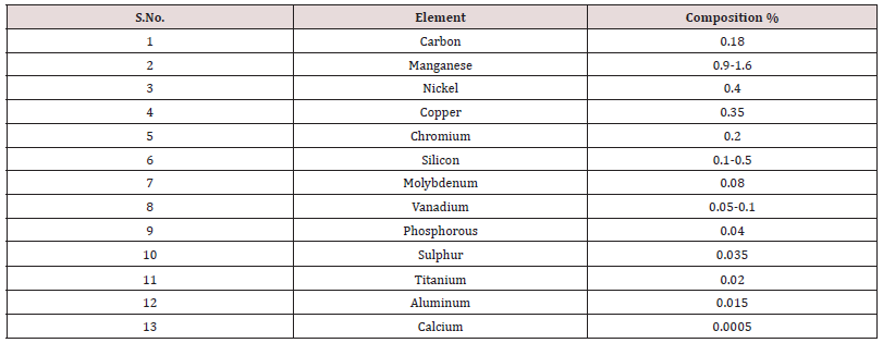
In this experiment, the residual stresses are developed in two types of joints those are Butt joint and T joint by using the material DH 32 steel plate. And the material is fully killed steel. The dimensions of the butt joint for each plate is 100 mm × 100 mm × 25mm and T joint for each plate is 100 mm × 100 mm × 12.5mm. The composition of this material is shown in Table 1. The welding process was specified for this material is Shielded Metal Arc Welding experiment was done by [11].
Specimen Preparation
The experiment was carried out on butt joint and T joint. For butt joint, the thickness of plates is 25mm, so the penetration of weld material is low. To improve the penetration of welding, we used double V groove edge preparation for base metal with 70 degrees angle. For T joint, 12.5mm thick material is used so it doesn’t need any edge preparation. The mechanical properties of DH32 steel plate as shown in the Table 2. There are four strain gauges are placed in different weld zones in the base plate. In butt joint, the four strain gauges are placed at 90mm, 70mm, 50mm, 30mm in the x - direction. In T joint, the strain gauges are placed at 45mm, 35mm, 25mm, 15mm from the center line of the base plate. Each strain gauge is connected to the Wheatstone bridge as unknown resistance separately. By using the potentiometer, the bridge gets balanced that means the output Voltage will be zero [12-14]. When the welding process starts, Internal stresses were developed. because of these stresses, the strain gauge changes its resistance then the Wheatstone bridge gets unbalanced, and the output Voltage will also change. From this Voltage we can measure internal Strain and Stress at that particular area. The stresses and strains are calculated from the equations 1 and 2 [15]. The features and details of strain gauges which are used in this experiment are given in Table 3. Using the shielded metal arc equipment and E6013 electrodes, the welding was carried out in a single pass which lasted for 30 seconds. Weld time is 20 seconds, the specimens were then allowed to cool down to room temperature. All welding precautions were taken into consideration during the specimen production to ensure the reduction error. The welding parameters are shown in Table 4. After the welding process, the samples were cleaned with a wire brush to remove carbon deposits.
Finite Element Analysis
In this study, the butt weld joint and T joint of two DH32 steel plates were modelled using ANSYS V19.2. To simulate these joints, the coupled analysis of Transient thermal and Static structural analysis. Thermal analysis has been carried out using the 3D element SOLID70, an eight-node quadrilateral element with a single degree of freedom having temperature at each node. Although the structural analysis has been carried out using the 3D element SOLID185, eight node quadrilateral elements having three degrees of freedom at each node (translation in the nodal x, y, z directions). The mesh generated 15,701 nodes and 3168 elements in butt joint. In T joint, 29,617 nodes and 6032 elements were generated. The analysis was solved and residual stresses generates by using the Element Birth and Death technique.
Element Birth and Death Technique
The material deposition is modelled using an element “birth and death” technique. To achieve the death element effect, ANSYS code does not actually remove the element from the model. Instead, the weld elements are first deactivated by multiplying their stiffness by a huge reduction factor. Meanwhile, to obtain the birth element effect, the ANSYS program the reactivates the death element by allowing its stiffness, element load etc. return to their original values [12].
Results and Discussion
Residual Stresses Measured from Experiment
The conventional strain gauges are attached to base plate at different weld zones. While passing the electrode, strain gauges are detached from the base plate because of overheat in welding process. In butt joint, one gauge detached. In T joint, two strain gauges are detached from the base plate. Now, we got the output voltages from the sensors are obtained only three in butt joint as well as two output voltages in T joints. The remaining voltages are calculated by using polynomial extrapolation. From the strain gauges are used to calculate the strains of the base metal from output voltages by using the Equation 1. From Equation 2, The residual stresses are calculated from Hooks law i.e., Equation 3. The elastic modulus for the DH32 steel is 201 GPa. Residual stresses are measured for both butt joint and T joint are separately at the different weld zones separately which mentioned in Table 5,6 respectively.
Residual Stresses Predicted from FEA
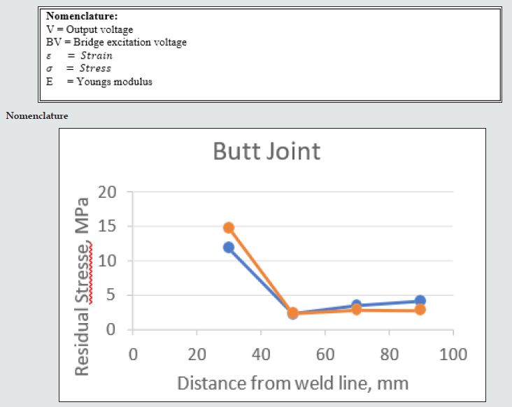
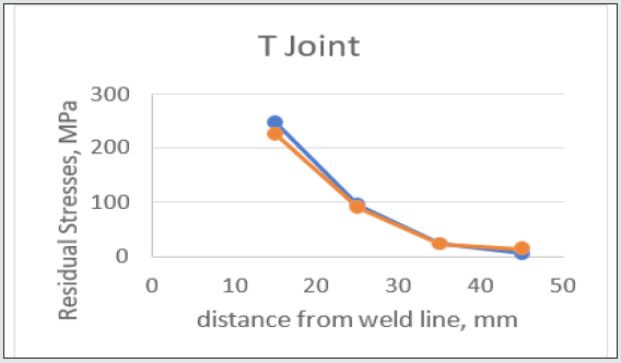
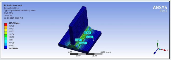
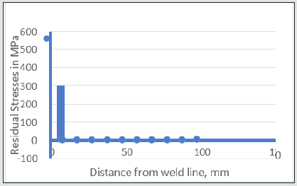
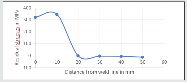
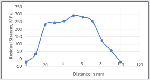
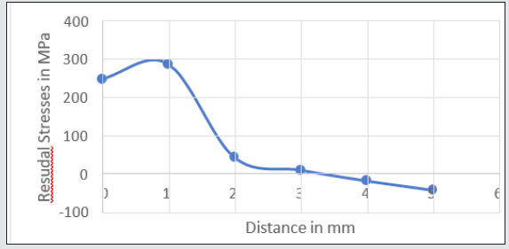
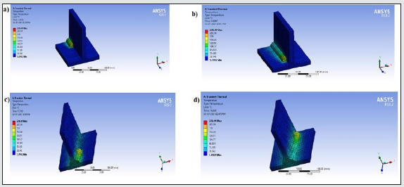
The measured residual stresses obtained from the experiment are evaluated with simulation predicted values at their respective places in butt joint and T joint. (Figures 1,2) demonstrate the predicted and measured residual stress distribution in the base metals of butt joint and T joint respectively. It is known from the figure that the numerical simulation results are in good agreement with the measured residual stress, which confirms the validity and feasibility of simulation results by using simulation software. From the (Figures 1,2), the blue lines indicates that the values obtained from the experiment and the other lines are indicates the FEA results where the strain gauges are placed in the base metals and heat affected zones (Figures 3,4) shows the residual stresses where strain gauges are attached to the base plates of butt joint and T joint individually. The predicted residual stresses in butt joint are 14.71 MPa, 2.41 MPa, 2.89 MPa and 2.82 MPa at the distance of 90mm, 70mm, 50mm and 30mm from the weld line respectively. The predicted residual stresses in T joint are 224.7 MPa, 56.96 MPa, 23.68 MPa, 14.34 MPa at the distance of 15mm, 25mm, 35mm, 45mm from the weld centre line. On the other hand, (Figure 5) shows the temperature distribution in butt joint. The total weld cycle time is 50 seconds but the welding time is 20 seconds in both butt joint and T joint. The maximum temperature reached in butt joint is up to 350℃. (Figure 6) shows the temperature distribution in T joint. The maximum temperature obtained in T joint is 228℃. The maximum temperature in T joint is less than butt joint, because butt joint plates are high thickness plates. (Figures 7,8) shows the transverse residual stresses along the weld line and vertical to the weld line in butt joint respectively. Residual stresses which along the weld line is hat like distribution. The maximum stress exhibits along the weld line are 559.9MPa and the minimum compressive stress is 339MPa. It can be seen from (Figures 7,8), the maximum transverse residual stress occurs at neat the weld line that is 255MPa at the middle portion of weld line.
Figure 5: Transient Temperature distribution in butt joint. a) Temperature distribution at time, t= 1 sec b) Temperature distribution at time, t= 7 sec c) Temperature distribution at time, t= 14 sec d) Temperature distribution at time, t= 18 sec
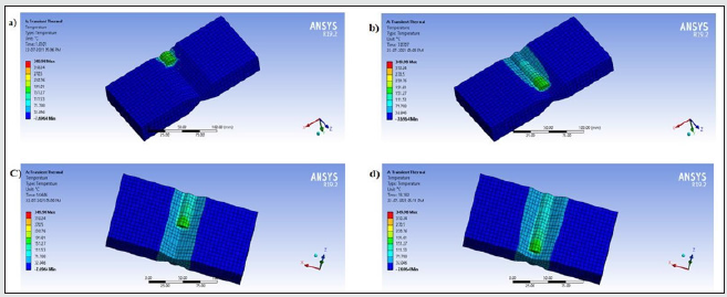
Figure 6: Transient Temperature distribution in T joint. a) Temperature distribution at time, t= 2 sec b) Temperature distribution at time, t= 7 sec c) Temperature distribution at time, t=13 sec d) Temperature distribution at time, t= 18 sec
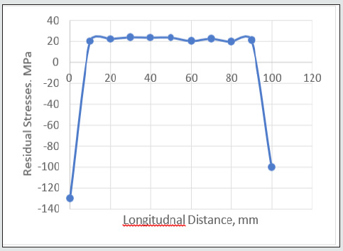
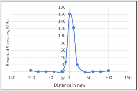
It can be seen from the results of (Figure 10). that the longitudinal residual stress of DH32 steel is distributed in a cap shape, the middle position in weldment along welding direction is tensile stress, and the two ends are compressive stress. The highest value of longitudinal residual stress is 160 MPa and minimum value represents its compressive strength of the material. In addition, it can be found that the longitudinal residual stress has a maximum value in the middle portion of weldment. Because, during the welding, when welding heat source has not reached the middle of the weld, the base metal here is not subjected to the longitudinal directional stress. When the welding heat source moves here, the base material near weld is subjected to longitudinal compressive stress. When the welding heat source is far away from here, the material shrinkage at cooling is subjected to the tensile stress given at both ends of weldment. Therefore, the area near the weld experiences the variation process of compressive and tensile stress, which finally exceeds the yield strength of the material. As shown in (Figure 9), the longitudinal residual stress near the weld zone is 400 MPa. With the increase in the distance, the original tensile stress is transformed into compressive stress, and the compressive stress is up to -70 MPa, and when moved away from the weld, the longitudinal residual stress gradually changes to zero, indicating that in the welding process, the heat effect near the weld area is large, the thermal expansion is large, and the shrinkage effect is large at cooling. On the contrary, the effect far away from the weld area is small. In addition, the longitudinal residual stress near the weld is large, while the residual stress far away from the weld is relatively small, which is also related to the large thermal stress generated by the uneven temperature field during cooling (Figure 10).
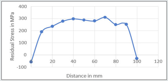
From the (Figures 11,12) we can observe distribution of Transverse residual stresses in T joint. From (Figure 11), it can be seen that the transverse residual stress also exhibits a hat-like distribution in which the maximum transverse stress occurs at both ends of the cap edge and shows the tensile stress, which is approximately 280 MPa, and the compressive stress at both ends is about 260 MPa. It can be seen from (Figure 7). that the maximum transverse residual stress near the weld is about 250 MPa in the vertical weld direction, and at far away from the weld, the stress value tends to zero, and the stress is all tensile stress. In addition, it is found by comparison that the transverse residual stress is significantly lower than the longitudinal residual stress (Figures 13, 14).
Conclusion
In this paper, the temperature field and the residual stress distribution of DH32 steel T-type and Butt joint single- pass welding have been measured by using conventional strain gauges. To evaluate the experimental results, the residual stresses and temperature distribution are predicted in Finite Element Analysis. By using Element birth and death technique in FE model the results of residual stresses and temperature distribution results are got accurately. The Transverse and Longitudinal residual stresses are not much more than yield strength of the material in both butt joint and T joint. The results of residual stresses showed that both transverse and longitudinal residual stresses reached peak values only at near the weld region. Away far from the weld zone, residual stresses decreased to negligible values. The experimental residual stresses for both butt joint and T joint are good agreement with FEA results only at base plate but not in HAZ because of its high temperature, the strain gauge limits exceeded. It was found that the conventional strain gauges can measure only in low temperature conditions [16].
References
- Chen Q, Fei F, Yu S, Liu C, Tang J, Yang X (2020) Numerical Simulation of Temperature Field and Residual Stresses in Stainless Steel T-Joint. Transactions of the Indian Institute of Metals 73: 751-761.
- Mackerle J (2004) "Finite element analysis and simulation of welding-an addendum: a bibliography (1996 2001), Modelling Simul Mater Sci Eng 10: 295-318.
- Barosum (2009) "Residual stress effects. on fatigue life of welded structures using LEFM", Engineering Failure Analysis 1(16): 449-467.
- David R (2001) "Finite Element Analysis M.sc Thesis, Massachusetts Institute of Technology, Cambridge, MA 02139.
- Gurinder S (2013) "Finite element simulation of residual stress in butt welding of two AISI 304 stainless steel plates". International Journal on Theoretical and Applied Research in Mechanical Engineering 2(1): 75.
- Jeyakumar MT, Christopher T, Narayanan R, Nageswara B (2013)"Residual Stress Evaluation in Butt-welded joint of ASTM A36 Steel Plates", International Journal of Electronics Communication and Computer Engineering 4: 581-587.
- Stamenkovic D, Ivana V (2009) "Finite Element Analysis of Residual Stress in Butt Welding Two Similar Plates". Scientific Technical Review 511(1): 57-60.
- ASTM (2008) Standard A131, 2008.
- https://www.shipbuilding-steel.com/Products/DH32.html
- Consulting TEA, Andersen BL & Consulting TEA (nd) Heat Input & Interpass temperature during welding 1-6.
- Filho AVS, Rolim TL, Yadava YP, Cardoso FIB, Guimarães PB, et al. (2013) Development of methodology for measurements of residual stresses in welded joint based on displacement of points in a coordinated table. Materials Research, 16(2): 322-326.
- Magalhães RR, Junior ABV, Barra SR (2014) The use of conventional strain gauges evaluation for measurements of residual stresses in welded joints. Journal of the Brazilian Society of Mechanical Sciences and Engineering 36(1): 173-180.
- Eng JAM, Adak M, Cg S (2016) Journal of Applied Residual Deflections and Stresses in a Thick T-Joint Plate Structure 5(6).
- Teng T, Fung C, Chang P, Yang W (2001) Analysis of residual stresses and distortions in T-joint® llet welds 78: 523-538.
- Lanciotti A, Polese C (2008) Electric strain gauge measurement of residual stress in welded panels JSAED 44(1): 117-126.
- https://www.bestech.com.au/blogs/understanding-a-wheatstone-bridge-strain-gauge-circuit/

Top Editors
-

Mark E Smith
Bio chemistry
University of Texas Medical Branch, USA -

Lawrence A Presley
Department of Criminal Justice
Liberty University, USA -

Thomas W Miller
Department of Psychiatry
University of Kentucky, USA -

Gjumrakch Aliev
Department of Medicine
Gally International Biomedical Research & Consulting LLC, USA -

Christopher Bryant
Department of Urbanisation and Agricultural
Montreal university, USA -

Robert William Frare
Oral & Maxillofacial Pathology
New York University, USA -

Rudolph Modesto Navari
Gastroenterology and Hepatology
University of Alabama, UK -

Andrew Hague
Department of Medicine
Universities of Bradford, UK -

George Gregory Buttigieg
Maltese College of Obstetrics and Gynaecology, Europe -

Chen-Hsiung Yeh
Oncology
Circulogene Theranostics, England -
.png)
Emilio Bucio-Carrillo
Radiation Chemistry
National University of Mexico, USA -
.jpg)
Casey J Grenier
Analytical Chemistry
Wentworth Institute of Technology, USA -
Hany Atalah
Minimally Invasive Surgery
Mercer University school of Medicine, USA -

Abu-Hussein Muhamad
Pediatric Dentistry
University of Athens , Greece

The annual scholar awards from Lupine Publishers honor a selected number Read More...


