Lupine Publishers Group
Lupine Publishers
Menu
ISSN: 2643-6744
Review ArticleOpen Access
Modeling and Analysis of LTE Downlink System-3GPP Volume 1 - Issue 5
Farhan Alta F* and Haseeb Zafar M
- Electrical Engineering, University of Engineering & Technology Peshawar, Pakistan
Received: February 17, 2020; Published: March 04, 2020
*Corresponding author: Farhan Alta F, Electrical Engineering, University of Engineering & Technology Peshawar, Pakistan
DOI: 10.32474/CTCSA.2020.01.000125
Abstract
This research work figures out the permanence of downlink LTE (Long Term Evolution) applying System Level Simulator [1]. The outcomes retrieved are related to the sector throughput and BLER (Block Error Rate), the user throughput and the interrelated CQI (Channel Quality Indicator) while entire simulation process. The main focus is based on the throughput versus the UDO and Rb. The synopsis applied gone into two antenna pattern, two system bandwidths, three packet tabulating plans and various account of users in the cell. To encounter the users speed on the system permanence is additionally estimated. The radio situation and status is sculpted in aforementioned simulator depicting that the outcomes retrieved might be gone into as a first steps in confining an LTE network for markets. The system is modeled according to commercial aspects of LTE Network. The results clearly depict the importance of LTE utilization.
Keywords: LTE; OFDMA; SISO; MIMO; Scheduling; CQI; Throughput
Introduction
The rapid increase in demand for data packet based mobile systems and to meet the requirements of future communications, the 3GPP has developed LTE which is the next step of 3G networks. LTE provides large capacity and improved performance as compared to 3G. The objective is to develop the evolution of the 3GPP to a high data rate, good efficiency and low latency. To deal with the perpetually increasing need of packet-based mobile broadband systems and to fulfill the requirements of forthcoming mobile communications, 3GPP (3rd Generation Partnership Project) has regularized a new technology – LTE (Long Term Evolution)-as the upcoming level for the present 3G mobile networks. LTE is foreseen to accommodate an expansive room and an upgraded permanence correlated to the present 3G/HSPA (High Speed Packet Access) networks. The target of LTE was to elaborate a structural design for the transformation of the 3GPP radio-access technology proceeding to a huge-data-rate, reasonable-delay and packet improved radio access technology. The demands mentioned in [2] visualizes a huge speed data rates, reasonable delay, high spectral efficiency, measurable bandwidths, flat all-IP network framework and models, improved permanence for mobile speed etc.
Literature Review
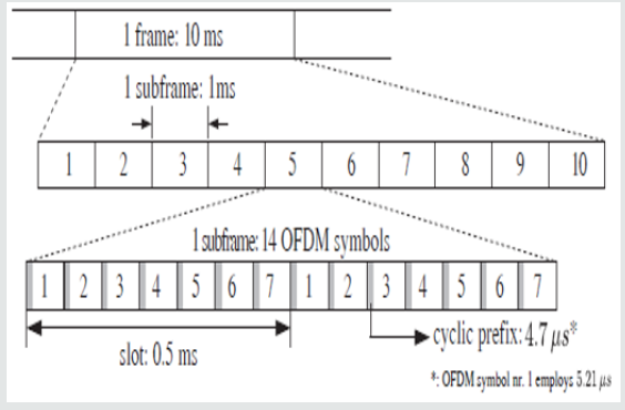
The Long-Term Evolution (LTE) Technology is proposed by 3GPP for improving the current mobile networks capability such as data rate, spectral efficiency, delay etc. The downlink LTE is based on OFDMA and MIMO. The advantage of using OFDMA is providing channel in time and frequency. The LTE downlink is primarily discriminated by OFDMA as multiple access scheme and MIMO (Multiple Input Multiple Output) technology. The advantage of setting up OFDMA technology over downlink LTE is the potential of assigning sufficient space on both time and frequency, granting various users to be tabulated at a time. The LTE PHY layer surrogates the Code-Division Multiple Access (CDMA) access technology made use of in 3G rules, regulations and standards including an advanced Orthogonal Frequency-Division Multiplexing (OFDM) PHY layer, that involves the PHY ways and means no more extend over in the code and time domain, except the frequency and time domain (in the two scenarios and also the space domain in case that MIMO is adapted).System permanence including respective point user (end user) know-how rely over the generation and transmission situations, the mobile tool feedback, that is characterized over evaluations, and the tabulating method in the eNodeB (Evolved NodeB). Packet tabulation is among the LTE RRM (Radio Resource Management) functions, which is under obligation for assigning ways and means toward the end users and, while executing the tabulated outcomes, Packet scheduling might take into consideration the channel quality information from the UEs, the QoS (Quality of service) requirements, the buffer status, the interference condition, etc. [3-6]. Like in HSPA or WiMAX, the scheduling method applied is not described in the rules and regulations although scheduling algorithm is eNodeB vendor defined (Figure 1).
In LTE, DL transmissions are organized into radio frames with a duration of 10ms, both for the Time Division Duplex (TDD) and Frequency Division Duplex (FDD) modes. Focusing just on the FDD case, each radio frame is subdivided into ten subframes of 1 ms each, subsequently divided into two slots and seven OFDM symbols each. In order to avoid inter-symbol interference, a CP is added to the beginning of each symbol, with a length of 5.21 micro sec for the first symbol or 4.7 micro sec for the remaining six symbols. A longer CP configuration is also standardized but is not considered in this work (Table 1).
Methodology
As in other contemporary communication systems, such as W-CDMA or IEEE 802.11n, LTE employs Bit-Interleaved Coded Modulation (BICM), which has been shown to improve performance compared to systems employing symbol-wise interleaving (Figure 2).
Transmitter
Comprised of a channel coder, a bit inter-leaver, and a modulator (M). It maps the input bit stream b to the transmit vector x.
Channel
Which outputs the symbol vector y and defines a transition probability density function (pdf) p(y/x) depending on the channel state.
Receiver
Which outputs the received bit stream ^b. It is comprised of an equalizer and demodulator, de-interleave, and channel decoder.
Simulation Results
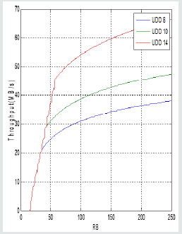
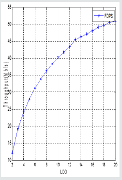
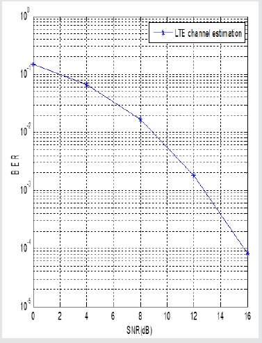
Figure 3 below shows the throughput increase for UDO 8, 10 and 14 w.r.t the RB. It increases as RB increases. The UDO 14 has better performance than others. Figure 4 shows the throughput w.r.t the UDO using FDPS. It increases as UDO increases. Figure 5 below shows the channel estimation of LTE using MMSE method. The BER is plotted versus SNR. It is clear that the BER decreases with SNR increase.
Conclusion
This research work assesses the permanence of downlink LTE utilizing System Level Simulator from [1]. We simulate LTE system level modeling and simulation based on practical channel parameters. The downlink performance is analyzed in terms of throughput versus the UDO and Rb. The results clearly show that the throughput increases with increasing the UDO and Rb. The results also indicate the importance of LTE in mobile networks. The work can also be extended to uplink and full-duplex system for future work. Sector throughput, user throughput and BLER were the signs of permanence which were sorted out, and the CQI mapping was conjointly represented in particular condition to corroborate the throughput values. The radio framework has been modeled in the simulator; the outcomes retrieved could be considered reliable for architecting LTE network commercially.
References
- JC Ikuno, W Wrulich, M Rupp (2010) System level simulation of LTE networks. 2010 IEEE 71st Vehicular Technology Conference, Taipei, Taiwan.
- 3GPP TR 25.913v8.0.0 Release 8, Requirements for evolved UTRA (E-UTRA) and evolved UTRAN (E-UTRAN)
- Ramli HAM, K Sandrasegaran, R Basukala, W Leijia (2009) Modeling and simulation of packet scheduling in the downlink long term evolution system. 15th Asia-Pacific Conference on Communications, Sydney, 68-71.
- Ramli HAM, R Basukala, K Sandrasegaran, R Patachaianand (2009) Performance of well-known packet scheduling algorithms in the downlink 3 GPP LTE systems. IEEE 9th Malaysia International Conference on Communications, Malaysia, pp. 815-820.
- Capozzi F, D Laselva, F Frederiksen, J Wigard, IZ Kovacs, et al. (2009) UTRAN LTE Downlink System Performance under Realistic Control Channel Constraints. IEEE 70th Vehicular Technology Conference Fall, USA, 1-5.
- 3GPP TS 36.300v8.12.0 Release 8, Evolved universal terrestrial radio access (E UTRA) and evolved universal terrestrial radio access network (E-UTRAN); Overall description; Stage 2.

Top Editors
-

Mark E Smith
Bio chemistry
University of Texas Medical Branch, USA -

Lawrence A Presley
Department of Criminal Justice
Liberty University, USA -

Thomas W Miller
Department of Psychiatry
University of Kentucky, USA -

Gjumrakch Aliev
Department of Medicine
Gally International Biomedical Research & Consulting LLC, USA -

Christopher Bryant
Department of Urbanisation and Agricultural
Montreal university, USA -

Robert William Frare
Oral & Maxillofacial Pathology
New York University, USA -

Rudolph Modesto Navari
Gastroenterology and Hepatology
University of Alabama, UK -

Andrew Hague
Department of Medicine
Universities of Bradford, UK -

George Gregory Buttigieg
Maltese College of Obstetrics and Gynaecology, Europe -

Chen-Hsiung Yeh
Oncology
Circulogene Theranostics, England -
.png)
Emilio Bucio-Carrillo
Radiation Chemistry
National University of Mexico, USA -
.jpg)
Casey J Grenier
Analytical Chemistry
Wentworth Institute of Technology, USA -
Hany Atalah
Minimally Invasive Surgery
Mercer University school of Medicine, USA -

Abu-Hussein Muhamad
Pediatric Dentistry
University of Athens , Greece

The annual scholar awards from Lupine Publishers honor a selected number Read More...


