


Lupine Publishers Group
Lupine Publishers
ISSN: 2637-4668
Review Article(ISSN: 2637-4668) 
Numerical Investigation of Structural Behaviour of Historical Stone Arches Volume 3 - Issue 2
Received: January 30, 2019; Published: February 25, 2019
Corresponding author: Marco Bovo, Research Assistant, DICAM, Department Civil, Chemical, Environmental and Materials Engineering, University of Bologna, Viale Risorgimento, 2 - 40136 Bologna, Italy
DOI: 10.32474/TCEIA.2018.03.000160
Abstract
This paper presents the numerical analysis of the structural behaviour of an historical masonry storehouse in Trieste, Italy. The large complex subject of the study is dated back to XIX Century and it is nowadays disused and in an advanced state of deterioration. The monumental building, object of detailed building survey defining geometry and characteristics, were extensively studied and analysed by means of a comprehensive experimental campaign conducted on its walls, foundations and arches. The main outcomes of the in-situ and laboratory tests allowed to defining the properties and the behaviour of some structural elements. The collected experimental data allowed defining and calibrating of detailed finite element models of the building composed of walls, columns, arches and vaults. The main goals of the modelling were the calibration of global material parameters to obtain a correct interpretation of the experimental tests conducted and the study of behaviour and capacity of the building when subject to horizontal loadings, such those due to a seismic excitation. The collected experimental data are compared here with the numerical results. Furthermore, the finite element models were used to perform numerical analyses under horizontal forces: linear analyses were conducted in order to estimate the important stiffening contribution of vaulted floor of the building and to define an equivalent not curved 2D diaphragm; nonlinear analyses were performed to estimate the ductility of the stonework arches-vaults system, taking also into account, or excluding, the flexibility of the foundation system previously calibrated. The approach adopted in the present paper proved to be effective and provide for an effective tool for evaluating the seismic vulnerability of complex masonry structures. Furthermore, the main outcomes in the paper will allow a properly design of future strengthening and conservation interventions for the increased design loading levels associated with the new intended use of the construction.
Keywords: Seismic assessment; Arch-vault systems; Historical construction; Pushover analysis; Deformable floor
Introduction
The seismic assessment of complex existing masonry building often requires numerical models to be used in order to properly evaluate the actual structural response of the system, when subject to several loading conditions [1]. In this framework, the choice of the more suitable numerical model to be adopted in the analysis process is a fundamental aspect, in order to reach both a correct interpretation of the structural behaviour and to limit the computational effort. This aspect is particularly important for large masonry buildings, where a comprehensive detailed model of the whole building coupled with a non-linear material constitutive model could heavily increase the computational cost and the efforts necessary for the analysis and the post-processing of results. The adoption, if possible, of detailed models of only limited portions or elements of the building (partial model) could represent an interesting compromise on the one hand, but on the other it introduces the problem of setting-up a realistic distribution of boundary conditions, simulating the excluded portions. This type of approach can be more easily followed when dealing with constructions composed of many identical recurring elements.
A further key aspect to be carefully considered when dealing with the seismic assessment of structures, concerns the evaluation of their ductility (linked to ductility of single elements and therefore ductility of materials) which depends on many different factors. Among these, maybe the most important are geometry of the structure [2] and nonlinear behaviour of masonry, the latter depending on shape and strength of bricks or stones, masonry texture, thickness of mortar layers and interface between mortar and stone [3]. In order to properly take into account all these aspects, the numerical modelling phase should be combined with an appropriate experimental campaign, able to provide for the outcomes necessary for an accurate calibration of constitutive relations introduced in the model.
In the present paper, the main results obtained from the numerical analyses carried out on the ancient storehouses situated in Trieste, in the North-East of Italy, are presented. The large complex depicted in Figure 1, dates back to XIX Century and it was used in the past to collect and store the wheat incoming to the Trieste harbour. The entire structure has a C-shape plan, presenting two long wings characterized by perimeter stonework walls transversally connected by 47 pairs of main stone arches. The main arches are further connected by secondary stone arches and brickwork vaults at floor level. To date, the storehouses are in advanced state of deterioration but they have been included in a huge restoration project of the area, aimed at the transformation in a shopping centre. A series of experimental in-situ load tests were conducted on some selected structural elements (some arches and foundation plinths), in order to assess the structural behaviour of the building when dealing with the vertical loads prescribed by the new intended use and to estimate its actual structural safety level, the lot allowing for a fine tuning of the strengthening interventions.
Figure 1: Aerial view of the XIX Century “ex-Silos” storehouses in Trieste (in the North-East of Italy).

The aims of the modelling were: calibration of material parameters necessary to obtain a correct interpretation of the experimental tests conducted on the building and to study the behaviour and the capacity of the building when subject to horizontal loadings, such those due to a seismic excitation [4-6]. First, the geometrical global model was defined, starting from the results of the building survey [7], in terms of dimensions, thicknesses and different textures of the various structural elements [8]. The elastic material properties were calibrated by preliminary finite element analyses through the comparison with the results of selected experimental in-situ tests. In particular, static tests on stone arches under service loading levels were considered. After the calibration process, the interaction between consecutive pairs of main arches, linked by secondary arches and cross vaults, has been analysed in detail by means of a partial model, in order to define the property of an equivalent membrane element, to be introduced inside the model as an alternative to the real curved geometry of vaults [9]. Finally, nonlinear analyses on the partial model of the arches-vaults system subject to horizontal loadings (pushover analyses) were carried out, with the aim of assessing the capacity and ductility against seismic actions of this type of vaulted structures taking into account, or excluding, the flexibility of foundation of the internal columns. As far as the soil-foundation interaction is concerned, the continuous foundation under the walls was considered as rigid, while trilinear springs were introduced under the foundations of stone columns. Results of experimental tests on plinth foundations were used to define the behaviour of the springs.
Description of Building and Experimental Campaign
The “ex-Silos” storehouses have a C-shape plan composed of three main units: two long wings with similar structural and geometric characteristics and a front building connecting the two wings. It is not considered in the present investigation because it was not object of the analysis nor of the tests.
A detailed survey of the whole complex, provided for the dimensions of the wings, which are 316×27 meters, with an internal courtyard about 29 meters wide (see Figure 2). Each wing has two floors about 8 and 12 meters high, respectively, for a total of 20 meters from ground level. The bearing perimeter walls are connected in transverse direction at the first floor, every 6.50m, by a pairs of main arches supported by a central internal column. The main arches start at 2-2.5 meters height from the ground level, have a span of about 12-13 meters, key brick height between 6 and 6.5 meters from ground level. In longitudinal direction the internal columns are linked by the secondary arches about 2 meters thick. The vertical load-bearing walls are made of very large rectangular limestone blocks, up to 30-40cm long, with bed joints of poorly hydrated lime mortar. The thickness of the perimeter walls is approximately 1.60 meters at the ground floor and 1.0 meter at the first floor. Arches and columns have usually a very good texture, whereas the stone brick arrangement of longitudinal walls is much more irregular and often with very thick and irregular mortar layers (up to 3-4cm). The first story of both wings has stonework vaults with a maximum height of 8 meters from the ground level. The pairs of main arches assure a considerable rigidity in transverse direction and a very high load carrying capacity to the structure and, connecting the central columns with the perimeter walls, they bear both vault and the upper wood pavement load. At the first floor, vaults bear the load of the wooden floor, made of beams with about 1 meter of spacing, a wooden floor and, in some parts of the building, an overlying concrete slab of more recent construction. The brickwork vaults have a 40-45cm constant thickness. Moreover, the brickwork has in general a good texture, with good compressive strength bricks interposed by thin lime mortar joints. Vaults are tunnel vaults, except for the last three bays per building, where they are replaced by cross vaults. From a series of dugouts, conducted under portions of perimeter walls and under some columns, it was possible to establish that the thick perimeter walls continues below the ground level for about 1 meter, with an enlargement of 40-50cm. There, the foundation is constituted by a layer 70cm thick of poor mortar, laid on a further layer 50cm thick of pebbles and stones mixture arranged with irregular texture. The surveys conducted on the perimeter columns showed stone foundations made of the same stonework as the substructure. The surveys conducted on the central columns revealed a foundation structures similar to that of the perimeter walls, with a series of enlargements by the four edges of the section. Moreover, according to the original design documentation, the foundation of walls and columns, at -4.0m from the ground level, lay on thick stone plates supported by fir-tree piles embedded in the soil in order to improve soil consolidation and load-carrying capacity.
Figure 2: Plan view of the ground floor the storehouses with indicated the structural elements experimentally tested in Bovo et al. (2017) and the wing object of the FE global model.

For an adequate characterization of the structural properties, different kinds of test have been conducted, at different scale levels. The mechanical properties of the stone masonry walls were obtained by compression tests on both stone cored specimens and full-scale stonework wall specimens. As far as the stone arches are concerned, in-situ tests were carried out with the purpose of investigating their structural response under different types of loading conditions. The arches were tested with symmetric and asymmetric static loading configurations and then with dynamic excitations, in order to assess the corresponding key parameters of the structural system. In Figure 2, the position of the four arches tested is showed. Finally, in order to characterize the behaviour and the flexibility of the column foundations, four plinths were tested under vertical static loading. An extensive description of the experimental systems adopted and the main outcomes of the experimental campaign are reported in Bovo et al. [7].
Numerical Modelling and Interpretation of Experimental Tests
The FINITE ELEMENT MODELS
Figure 3: Finite element models of the storehouses: (a) View of the global and (b) local FE model adopted in the present study.

In order to properly understand the structural behaviour of the storehouses, a 3D global finite element (FE) model of the wing on railway station side (see Figure 2), was obtained by reproducing the geometry of the building. The global FE model is showed in Figure 3a. Reliability of the numerical model strongly depends from the choice of the mesh and from the constitutive model, which usually varies according to the specific phenomena of interest [10-12]. In this framework, and following the classical literature classification, brickwork and stonework can be modelled at different approximation levels, by means of micro-element models, smeared models [13,14] and macro-element models, each method having its own advantages and drawbacks [15]. For example, in Gambarotta & Lagomarsino [16] a mortar joint damage model is proposed for application in micro-model elements and, in a companion paper Gambarotta & Lagomarsino [17], a homogenization procedure leads to a continuum model for smeared application. In the two papers, some examples of application of both models are reported. In Galasco et al. [18], a macro-element model is adopted and the results presented confirm the good reliability of the model implemented. In Szołomicki [19], a homogenized approach based on limit analysis is described and the issues of calibration and sensitivity of the model are addressed. Furthermore, in Stablon et al. [20] a new approach based on a homogenized damage model, that automatically addresses the problem of localization of deformation, is described.
In the present work, due to the wide size of the system under analysis and with the aim of limiting the computational efforts, a homogenized masonry material simulating the properties of both stone and mortar was adopted [21-23]. Consequently, the properties of the adopted finite elements are representative of the global behaviour of brickwork and stonework. In more details, the numerical FE model of Figure 3a is made of about 4˙400˙000 finite elements, pentahedron with 6 nodes (wedge elements) or hexahedron with 8 nodes (brick elements). The structure at ground level was fully restrained. The formulation of both types of finite elements is based on the isoparametric procedure. Since the experimental in-situ tests reached the service load level, in the numerical analyses carried out to reproduce the experimental results, a linear elastic constitutive behaviour was adopted. The assigned elastic modulus of the masonry was obtained by matching numerical and experimental results corresponding to the symmetric loading tests of the arches, as it will be discussed in the following. The global model resulted very expensive in terms of computational time and so the authors decided to consider only a limited portion of the FE model. To this purpose a local FE models has been extracted from the global one. In fact, due to its considerable size, the adoption of a refined mesh of the entire wing produces excessive computational time both for analysis and result post-processing phases [24]. Considering that the structural archvault system is longitudinally recurring along both the two wings a partial FE model of a representative portion of the wing was also modelled, thus limiting the computational effort without losing important aspects of the structural behaviour [25,26]. The partial FE model, composed of about 310˙000 finite elements, is showed in Figure 3b. A typical transverse bearing system was selected from the same wing building previously discussed. It is composed of three pairs of transverse main arches and the elements connecting them (perimeter walls, vaults, secondary arches). A system of constraints was applied on the boundary surfaces of the removed portions of building, thus preventing any displacement along Y-direction of Figure 3b. Since not all the arches and vaults had exactly the same geometry, the finite element mesh was created by using the geometry of the portion of the northern building (on the Railway Station side) with at the center the arch n. 4 of Figure 2 and experimentally subject to in-situ testing. In order to verify the representativeness of the partial model (Figure 3b) with respect to the global model (Figure 3a), a preliminary numerical analysis was performed on both the two models. Due to the high stiffness of the bearing elements along the longitudinal Y-direction, the numerical results from the two models were practically coincident. Even if the local numerical model considers a limited portion of the building, it allowed a properly understanding of the interactions between the contiguous main arches and vaults. Furthermore, a series of numerical analyses for horizontal loading, has been performed by the authors on the local model with the main goal to study archesvaults interaction (Section 4).
Interpretation of Tests on Stone Arches
Numerical predictions coming from the local FE model are compared with experimental results concerning the tests on arches. Both static (for symmetric and asymmetric loading conditions) and dynamic test are considered in the analyses. According to the static symmetrical test set-up, two equal vertical forces were applied at quarters of the arch span, while in the asymmetrical scheme only one vertical force was applied to the right quarter of the arch span.
Deflections measured under the symmetrical static loading scheme were used to properly identify the elastic modulus E and the shear modulus G of the equivalent smeared stonework material (considered homogeneous throughout the mesh). The comparison of deflections for asymmetric static loading was used to verify the reliability of the numerical model. The calibration procedure using a linear elastic constitutive model gave an elastic modulus E=1800MPa and a shear modulus G=750MPa (with Poisson ratio v=0.20 as a consequence).
Figure 4: Vertical displacement of arch n. 4 subject to static load test: experimental displacements compared with numerical predictions for (a) symmetric and (b) asymmetric loading conditions.

Figure 4 shows the comparison between the experimental vertical deflection of arch n. 4 and the numerical predictions, obtained from the partial model, via linear static analysis for three different loading levels (150kN, 250kN and 350kN applied at both quarters). In confirmation of the assumed values for the elastic properties, Figure 4 further shows that even in the case of asymmetrical loading scheme, matching between experimental and numerical results is very satisfactorily for each loading level as far as arch n. 4 is concerned.
Numerical predictions were also compared with vertical displacements experimentally measured during tests on other arches (different from n. 4), under symmetrical conditions (Figure 5a-c, respectively for three loading levels of 100kN, 250kN and 350kN). In Figure 6a-c, the experimental and numerical displacements under the asymmetrical loading conditions are also reported, respectively for 100kN, 200kN and 350kN loadings. In this case, the maximum displacement is attained at the loaded quarter (on the right). In both cases, the numerical results fit satisfactorily with the experimental outcomes, confirming that the model is representative of the real behaviour of the structure in the linear range.
Figure 5: Experimental and numerical vertical displacements on arches tested under symmetric loading condition: (a) 100 kN, (b) 250 kN and (c) 350 kN.

A dynamic modal decomposition analysis was also performed on the same elastic FE partial model in order to identify the main natural vibration frequencies of the partial structural system. The shape of the building and the lack of rigid diaphragms at various floors suggest that even the dynamic analysis on a limited portion of the whole system could be quite representative, at least as far as the vibration modes in the vertical direction are concerned. The two main frequencies activating most of the mass in the vertical direction are f1,num=12.01Hz and f2,num=15.86Hz. The numerical deformed modal shapes are shown in Figure 7a-b, respectively.
The experimental dynamic tests carried out on four representative arches and described in Bovo et al. [7] showed a large scatter in the results due to differences in material quality and also dimensions. The experimentally identified frequencies exciting mass along the vertical direction range from 9.0 to 15.6Hz for the first mode shape and from 15.8 to 19.5Hz for the second one. Of course, this scattering cannot be captured by the numerical model. Nevertheless, the numerical frequencies obtained for the two modes identified fit with acceptable approximation with the average values of experimental frequencies, i.e. f1,exp=12.93Hz and f2,exp=17.95Hz.
Figure 6: Experimental and numerical vertical displacements on arches tested under asymmetric loading condition: (a) 100 kN, (b) 250 kN and (c) 350 kN.

Figure 7: Modal shapes of vertical vibration frequency of the structure identified via FE model: (a) first natural mode; (b) second natural mode.

Discussion
In conclusion, it can be stated that the finite element model is able to properly match both the static and the dynamic behaviour of the structural system, under service (elastic) conditions.
Tests on foundation elements
In order to estimate the load-carrying capacity and the vertical settlement of the foundation system, four typical plinths foundations (indicated with a blue circle in Figure 2) were experimentally tested with an increasing static vertical load. For each test, the vertical displacements of four points on the plinth were measured by means of two optical levels and the mean vertical displacement of the column base was calculated as the mean value of the four displacements. For each step, the loading was kept constant for 15-20 minutes. The maximum loading was reached after 2-4 hours of test and then kept constant for 14-16 hours before unloading. The force-displacement curves obtained for each of the four tested plinths are reported in Bovo et al. [7] with an extensive description of the testing procedure.
Figure 8: Force-settlement curves for static vertical loading on foundation of column n. 4 (see Figure 2): calibration of trilinear spring model by means of experimental results reported in Bovo et al. (2017).

In order to model numerically the inelastic behaviour of the soil when subject to vertical stresses, a tri-linear uniaxial spring was introduced at the bottom of the central column in the partial FE model. Its calibration was done by comparing experimental results coming from tests on column foundation n. 4, identified as the most representative of the whole structure, and numerical results (see Figure 8). The good correlation between experimental outcomes and numerical predictions confirms the suitability of the trilinear law adopted to simulate the foundations flexibility in the nonlinear range (see Section 5 of the present paper). Nonlinear springs would be required to take the flexibility of the soil into account in the nonlinear analysis of the structure when subject to horizontal loadings also. To this purpose, in the finite element model depicted in Figure 3b, the initial restraints assigned at the base of the columns were substituted (along the vertical direction) by a vertical trilinear spring rigidly linked to the whole column base cross-section.
Assessment of Arches-Vaults Interaction by Linear Analysis
The correct estimate of the membrane and flexural stiffness of horizontal (or sub-horizontal) diaphragms is fundamental for a reliable evaluation of the seismic response of a structure. As discussed in Cattari et al. [27], the role of floor diaphragms is significant both in terms of stiffening the structure and redistributing horizontal seismic loads among vertical bearing elements. In fact, when floors are deformable in their planes, arches and columns tend to deflect one independently from each other, each one activated by its own surrounding mass. As well known, this is true not only in the linear range but also, and particularly, in the case of strong horizontal actions (activating the nonlinear behaviour of materials): the deformable floor does not allow for effectively redistributing forces from elements undergoing strong nonlinear effects to still elastic or less damaged ones. This aspect is particularly important in the case at hand, due to the very different behaviour in term of mass distribution, stiffness and strength of external walls and internal columns. The assumption of the presence of rigid diaphragms at the floor level may, in principle, lead to significantly overestimate the redistribution of horizontal forces among vertical elements. The rigid floor assumption is also unrealistic considering the elongated shape of the two parallel storehouses of the building with a 1/12 ratio between the width/length dimensions.
Figure 9: Plan-view of the deformed FE model used for the study of horizontal stiffness (transverse direction) of the portion of structure considered: (a) with and (b) without vaulted floor.

For this reason, in order to assess the vaulted floor in-plane stiffness when the building is subject to horizontal forces, a linear static analysis was carried out by applying a horizontal force to the pair of main central arches of the partial model and acting along their principal direction, with horizontal displacements of the lateral arches constrained. This analysis was carried out with and without the presence of cross vaults. With reference to finite element models depicted in Figure 9, a 1000kN horizontal force was applied, obtaining horizontal displacements at the control point A equal to δA’=0.12 mm and δA’’=0.56mm, for the model with (Figure 9a) and without the vaulted floor (Figure 9b), respectively. These results show that the vaulted system plays a fundamental role in the structural behaviour, redistributing horizontal loads among arches pertaining to different transverse alignment, being its in-plane stiffness 3-4 times greater than the stiffness of the three longitudinal walls, when subject to the same set of forces in the transverse direction.
Hence, in order to properly assess the seismic behaviour of the whole structure or portion of it, the vaulted floor must be maintained. The model at hand could be simplified by replacing the current vaulted system with an equivalent plane diaphragm, according to Cattari et al. [27]. Elastic properties of the equivalent plane diaphragm, EV and GV, can be obtained from the following equations [27]:
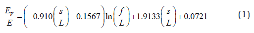

where:
EV ,GV : Young’s and shear modulus of the equivalent plane diaphragm;
E, G : Young’s and shear modulus of the vaulted floor;
s : thickness of the cross vault;
L : span of the cross vault;
f : rise of the cross vault.
By assigning the values of s=45cm, L=11.0m and f=3.0m for the case at hand, the ratio EV/E becomes 0.40, whereas GV/G is equal to 0.25. The equivalent plane floor then has elastic modulus EV=720MPa and shear modulus GV=188MPa. This diaphragm, with in-plane shear and longitudinal stiffness equivalent to the vaults system, can be used in a less detailed finite elements model, in order to reduce the computational effort.
Inelastic Behaviour of the Structure Subject to Horizontal Forces
In order to evaluate the behaviour of the building when subject to horizontal forces due to earthquake excitation, a nonlinear static pushover analysis [28,29] was conducted on the FE model reported in Figure 10. The nonlinear behaviour of masonry was obtained by using as yield function the Mohr-Coulomb criteria in principal stress space, with “yielding” occurring when a point reaches the yielding surface. For the definition of the Mohr-Coulomb yielding function, as suggested in NTC (2008) for historical stonework, the values 0.1MPa for cohesion and 21° for the friction angle were assumed. With reference to experimental values obtained and reported in Bovo et al. [7], the global failure collapse criterion was defined as the attainment of a principal compression strain of 3% in the masonry element.
Figure 10: Loading system applied to the partial FE model for the study of the nonlinear behaviour of the arches-vaults system.

As suggested in Galasco et al. [30], the use of pushover analysis for buildings with membrane deformable diaphragms presents more issues with respect to the simpler case of structures with rigid floors. For example, selection of the distribution of horizontal forces is a critical aspect since, in deformable-floor structures, the effects of higher order modes may be significant. Another crucial point of pushover methodologies, especially in the case of in-plane deformable diaphragms, is the choice of the control node to be monitored during the loading phase. In fact, remarkably different curves can be obtained by changing the control node even if with reference to the same floor.
In the present work, according to NTC [31], the force distribution was assumed proportional to the story shear distribution obtained from a dynamic modal analysis. Being of interest the structural behaviour of the building in the transverse direction, the applied force distribution is proportional to the shear forces obtained considering the natural vibration mode exciting the largest percentage of the structural mass in the transverse horizontal direction (X-dir. in Figure 10). During the load increments, the horizontal displacement along X-direction of the point B in Figure 10 was registered. Numerical results in terms of “base shearhorizontal displacement” at point B, monitored until the attainment of the failure condition, are reported in Figure 11 for two different restraint conditions at the column base: the fixed restraint (FR) and the trilinear spring (TS) condition discussed in Section 3.3.
In the same figure, the ideal equivalent elastic-perfectly plastic force-displacement curves are superimposed to the corresponding numerical nonlinear curves. The bilinear relationships are determined, according to NTC [31], by imposing the areas under the two curves, nonlinear and bilinear, to be equal (see Figure 11).
Considering the ideal equivalent bilinear curves, it can be verified that the more realistic model, with trilinear springs under the columns, shows a stiffness of the first ideal elastic portion about 20% smaller than that of model with fixed restraints, and a 17% reduction of the ideal yielding force. On the contrary, due to the flexibility of foundation-soil system, the ultimate displacement at the control node position is 60% greater than in the fixed restraint condition.
Figure 11: Base shear-horizontal displacement curves from pushover analysis of nonlinear FE model in Figure 10. FR: Fixed Restraint and TS: Trilinear Springs conditions for the foundations.

According to NTC [31], the equivalent bilinear curve can also be used to estimate the ductility of the structure, when subject to horizontal earthquake excitation. Ductility, defined as the ratio between displacement at failure and displacement corresponding to the yielding point of the ideal equivalent bilinear relation, is a very important issue in seismic engineering. In fact, it can be correlated to the capability of a building to drop the peak values of stresses in the structure during an earthquake. Furthermore, by means of the displacement ductility, the behaviour factor can be estimated, useful to perform a reliable spectral dynamic analysis of the structure so to reduce the computational effort needed to study the structure for many seismic loading combinations. In the case at hand, the ductility values are μFR=57.2/32.6=1.75 for the fixed restraint condition and μTS=90.1/33.3=2.70 in the case of deformable ground, modelled by means of trilinear springs. This aspect confirms the general criterion that the effect of earthquake forces in large buildings is, usually, less critical when the soil-structure interaction is considered, by introducing the soil flexibility inside the model.
Conclusion
Starting from the results of experimental static and dynamic tests described in Bovo et al. [7], FE models of a monumental stonework building located in Trieste (Italy) were assessed and calibrated. The good matching between numerical analyses and experimental tests on arches and foundation elements of the building confirmed the reliability of the partial model, which was then used for further and more complex analyses.
In this perspective, linear numerical analyses were carried out on the structure subject to horizontal loading, showing that vaults may have significant in-plane stiffness. Furthermore, they play an important role in the loading redistribution among parallel pairs of arches, increasing robustness of the structural system, thus suggesting the necessity of carefully protecting them from early failure during an earthquake. Finally, nonlinear pushover analyses were performed, considering the two modelling conditions of fixed restraints at the building foundations level and nonlinear behaviour of the soil-foundation system. It is shown that, in the second case, the building may exhibit a significantly larger ductility when subject to horizontal forces, very important in order to withstand effectively the seismic action.
The approach adopted in the present paper proved to be effective and provide for an effective tool for evaluating the seismic vulnerability of complex masonry structures. Furthermore, the main outcomes in the paper will allow a properly design of future strengthening and conservation interventions for the increased design loading levels associated with the new intended use of the construction [32].
References
- Rota M, Penna A, Magenes G (2010) A methodology for deriving analytical fragility curves for masonry buildings based on stochastic nonlinear analyses. Engineering Structures 32(5): 1312-1323.
- De Felice G (2011) Out-of-plane seismic capacity of masonry depending on wall section morphology, International Journal of Architectural Heritage 5(4): 466-482.
- Calvi GM, Kingsley GR, Eeri M, Magenes G (1996) Testing of Masonry Structures for Seismic Assessment. Earthquake Spectra 12(1): 145-162.
- D Ayala D, Speranza E (2003) Definition of Collapse Mechanisms and Seismic Vulnerability of Masonry Structures. Earthquake Spectra 19(3): 479-509.
- Cardoso R, Lopes M, Bento R (2005) Seismic evaluation of old masonry buildings. Part I: Method description and application to a case-study. Engineering Structures 27(14): 2024-2035.
- Asteris PG, Chronopoulos MP, Chrysostomou CZ, Varum H, Plevris V, et al. (2014) Seismic vulnerability assessment of historical masonry structural systems. Engineering Structures 62-63:118-134.
- Bovo M, Mazzotti C, Savoia M (2017) Structural Characterization of an Historical Building by Means of Experimental Tests on Full-Scale Elements. Advances in Civil Engineering, pp. 6819546.
- Sousa Gago A, Alfaiate J, Lamas A (2011) The effect of the infill in arched structures: Analytical and numerical modelling. Engineering Structures 33(5): 1450-1458.
- Giordano A, Mele E, De Luca A (2002) Modelling of historical masonry structures: Comparison of different approaches through a case study. Engineering Structures 24(8): 1057-1069.
- Massart TJ, Peerlings RHJ, Geers MGD (2004) Mesoscopic modelling of failure and damage induced anisotropy in brick masonry. European Journal of Mechanics - A/Solids 23(5): 719-735.
- Lourenço PB (1998) Experimental and numerical issues in the modelling of the mechanical behaviour of masonry. In: Roca P, Gonzálcz JL, Dilatey E, Lourenço PB (Eds.), Structural Analysis of Historical Constructions, vol. II. CIMNE, Barcelona, Spain, pp. 57-91.
- Mc Nary WS, Abrams DP (1985) Mechanics of masonry in compression. Journal of Structural Engineering, ASCE 111(4): 857-870.
- Lofti HR, Shing PB (1991) An appraisal of smeared crack models for masonry shears wall analysis. Comput Struct 41(3): 413-425.
- Lourenço PB, Rots JG, Blaauwendraad J (1998) Continuum model for masonry: parameter estimation and validation. Journal of Structural Engineering, ASCE 124(6): 642-652.
- Mistler M, Butenweg C, Meskouris K (2006) Modelling methods of historic masonry buildings under seismic excitation. Journal of Seismology 10(4): 497-510.
- Gambarotta L, Lagomarsino S (1997) Damage models for the seismic response of brick masonry shear walls. Part I: The mortar joint model and its applications. Earthquake Engineering and Structural Dynamics 26(4): 423-439.
- Gambarotta L, Lagomarsino S (1997) Damage models for the seismic response of brick masonry shear walls. Part II: The continuum model and its applications. Earthquake Engineering and Structural Dynamics 26(4): 441-462.
- Galasco A, Lagomarsino S, Penna A, Resemini S (2004) Non-linear seismic analysis of masonry structures. 13th WCEE. Vancouver, Canada, 1-6, Paper no. 843.
- Szołomicki JP (2009) Structural behaviour of masonry vaults. 18th International Conference on the Application of Computer Science and Mathematics in Architecture and Civil Engineering. Weimar (Germany), p. 7-9.
- Stablon T, Sellier A, Domede N, Plu B, Dieleman L (2012) Influence of building process on stiffness: numerical analysis of a masonry vault including mortar joint shrinkage and crack re-closure effect. Materials and Structures 45(6): 881-898.
- Brasile S, Casciaro R, Formica G (2007) Multilevel approach for brick masonry walls. Part II: On the use of equivalent continua. Computer Methods in Applied Mechanics and Engineering 196(49-52): 4801- 4810.
- Calderini C, Lagomarsino S (2008) A continuum model for in-plane anisotropic inelastic behaviour of masonry. Journal of Structural Engineering, ASCE 134(2): 209-220.
- Zucchini A, Lourenço PB (2007) Mechanics of masonry in compression: results from a homogenisation approach. Comput Struct 85(3-4): 193- 204.
- Genna F, Di Pasqua M, Veroli M (1998) Numerical analysis of old masonry buildings: A comparison among constitutive models. Engineering Structures 20(1-2): 37-53.
- Lourenço PB (2002) Computations of historical masonry constructions. Progress in Structural Engineering and Materials 4(3): 301-319.
- Rots JG (1991) Numerical simulation of cracking in structural masonry. Heron 36(2): 49-63.
- Cattari S, Resemini S, Lagomarsino S (2008) Modelling of vaults as equivalent diaphragms in 3D seismic analysis of masonry buildings. Proceedings of the 6th International Conference on Structural Analysis of Historical Construction, SAHC2008, Bath (United Kingdom) July 2-4, 1: 517-524.
- Barbato M, Gu Q, Conte JP (2010) Probabilistic push-over analysis of structural and soil-structure systems. Journal of Structural Engineering 136(11): 1330-1341.
- Kappos A, Penelis GG, Drakopoulos CG (2002) Evaluation of simplified models for lateral load analysis of unreinforced masonry buildings. Journal of Structural Engineering, ASCE 128(7): 890-897.
- Galasco A, Lagomarsino S, Penna A (2006) On the use of pushover analysis for existing masonry buildings. Proceedings 1st European Conference on Earthquake Engineering and Seismology, Geneva, Switzerland, September 3-8, Paper no. 1080 (CD-ROM).
- NTC2008 Norme Tecniche per le Costruzioni (2008). Italian Building Code (in Italian).
- Page AW (1978) Finite element model for masonry. Journal of Structural Engineering, ASCE 104(8): 1267-1285.


-

Mark E Smith
Bio chemistry
University of Texas Medical Branch, USA -

Lawrence A Presley
Department of Criminal Justice
Liberty University, USA -

Thomas W Miller
Department of Psychiatry
University of Kentucky, USA -

Gjumrakch Aliev
Department of Medicine
Gally International Biomedical Research & Consulting LLC, USA -

Christopher Bryant
Department of Urbanisation and Agricultural
Montreal university, USA -

Robert William Frare
Oral & Maxillofacial Pathology
New York University, USA -

Rudolph Modesto Navari
Gastroenterology and Hepatology
University of Alabama, UK -

Andrew Hague
Department of Medicine
Universities of Bradford, UK -

George Gregory Buttigieg
Maltese College of Obstetrics and Gynaecology, Europe -

Chen-Hsiung Yeh
Oncology
Circulogene Theranostics, England -
.png)
Emilio Bucio-Carrillo
Radiation Chemistry
National University of Mexico, USA -
.jpg)
Casey J Grenier
Analytical Chemistry
Wentworth Institute of Technology, USA -

Hany Atalah
Minimally Invasive Surgery
Mercer University school of Medicine, USA -

Abu-Hussein Muhamad
Pediatric Dentistry
University of Athens , Greece
