Lupine Publishers Group
Lupine Publishers
Menu
ISSN: 2637-4668
Research Article(ISSN: 2637-4668) 
Dynamic Analysis of a Real Footbridge Structure in a Najaf City Volume 2 - Issue 2
Saad Al Wazni1*, Alaa Abdalabbas2, Roqia Hayder2 and Zainab Mierr2
- 1Department of Civil Engineering, University of Kufa, Iraq
- 2Student at department of Civil Eng, University of Kufa, Iraq
Received: April 30, 2018; Published:May 08, 2018
Corresponding author: Saad Al Wazni, Department of Civil Engineering, Faculty of Engineering, University of Kufa, Iraq
DOI: 10.32474/TCEIA.2018.02.000133
Abstract
The presented study consists of a dynamic analysis of a real pedestrian bridge structure of about 35m span over the highway connect Kufa and centre city of Najaf (Iraq). The main objective of this analysis were to assess whether the dynamic properties of footbridge structure meets the main safety requirements with the appropriate verification criteria. The extracted dynamic properties of the structural bridge model are natural frequency and mode shape. ANSYS software is used to perform the analysis by the way of APDL method. In this study, the first seven vibration modes of the bridge model are extracted. The dynamic characteristics extracted by modal analysis of the adopted bridge structural model exhibited the uncomfortable of vibration modes compared with European standards.
Keywords: Dynamic properties, Modal analysis, Footbridge, Pedestrian bridge, Steel structure
Introduction
For any structure has own natural dynamic behaviour depend on its stiffness and mass. The dynamic behaviour of a structure is represented by dynamic properties such as natural frequency and mode shape. The modal analysis method is applied to extract the dynamic properties of the structure [1]. If the structure excited by the external force has frequency close to the it’s natural frequency, the resonance will occur and that means the structure will face higher vibrations [2]. The changes of the modal properties are related with geometry, material properties and mass of the structure. In the design of the structure, the extracted modal properties using dynamic analysis helps to specify the weakness that needs modifications. So, calculating the natural frequency and mode shape of a vibrating structure are a common types of dynamic analysis and they are called “eignvalue and eigenvector analyses” respectively.
Structural Dynamic System
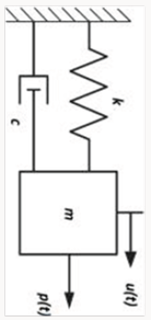
The natural frequency, ω, is in units of radians per second (rad/s). The typical units displayed on a digital signal analyser, however, are in Hertz (Hz). To analyse equation the system shown in the Figure 1, the force acting on the system is summed up. This becomes [3];
where 𝑥̈ is acceleration, 𝑥̇ is velocity, 𝑥 is displacement, 𝑐 is damping constant, 𝑘 is stiffness and F is excitation force. If the displacement and the force are written as a cosine function, such that:
x = X.cosωt (2)
and
F = Fo cosωn t (3)
the equation becomes:
−mω2. X.cos ωt + c.ω .X.sin ωt + k. X.cos ωt = F0cos ωn t (4)
For undamped vibrations, 𝑐=0, the equation becomes;
−mω2. X.cos ωt + k. X.cos ωt = F0cos ωn (5)
−m.ω2 .X + k.X = F0 (6)
and for free vibrations, 𝐹𝑜 = 0, the equation becomes:
−m.ω2.X + k.X = 0 (7)
m.ω2 = k (8)
Thus:
ω2 =k/ m (9)
where 𝜔 is the circular frequency of the structure.
Adopted Pedestrian Bridge Structure
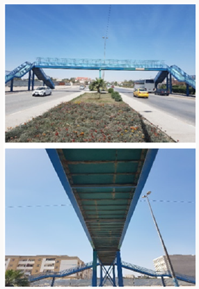
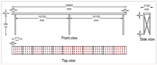
The studied bridge structure in this paper is a pedestrian bridge, is located in the city of Najaf in Iraq. The city of Najaf is one of the most prominent cities in Iraq and located to the south west of the capital Baghdad far about 170km. The adopted structure is a pedestrian steel bridge erected on the main highway leading to the centre of the Najaf near Alghadir neighbour. The highway under the pedestrian bridge is a three-lane one-way with two directions for vehicular traffic, as shown in the Figure 2. The geometry of the real bridge structure is flexural grid floor model with a length of 34.9m and 2.1m span width supported on the three piers at height of 5.5m, as shown the Figure 3. The grid floor of the bridge model consists of two main girders of H-section with dimension of (400 x 300 x 13) mm connected by transverse channel cross section beams of (200 x 50 x 5)mm distributed uniformly along the length of structure. In addition, the stiffeners beams of angle cross section with dimension (75 x 75 x 5)mm connected at the top of both main girders to carry floor plate of 3mm section, as shown the Figure 3. The three piers of the structure are distributed at distance of 16.15m c/c in the longitudinal direction of the structure. Each Pier has dual column with transverse distance of 1.5m c/c, and connected each to other by angle cross section stiffeners beams, as shown the Figure 3. All the parts of the bridge structural model are welded together. The values of material properties are assumed as follows: modulus of elasticity of E=200GPa, Poisson’s ratio n =0.3 and mass density r=7.850x10³kg/m3. The fences of the bridge structure are neglected and the stairs are represented as additional constrained in the supporting of the structural bridge model.
Finite Element Modelling
The FE model of the steel grid bridge structural model consists of 167 nodes and 249 elements with different element lengths. The hidden elements are considered for piers supporting in lateral direction. Those elements are adopted to suppress local behaviour of transverse stiffeners beams of piers. Thus, zero mass density is assumed for those elements with the same angle cross section dimensions of (50x50 x 5) mm. The selection of different element lengths is adopted in order to reduce the number of elements of FE model. The finite element analysis (FEA) is carried out using ANSYS-v18 software for structural analysis by Ansys Parametric Design Language (APDL) method. The APDL method is easiest way to simulate the structural model in ANSYS software. However, it is complex for who did not use it, so needs more experience to simulate the real structural model. The important of the APDL is easy, flexible and more effective if there are a lot of changed parameters and connect the ANSYS software with software such as MATLAB software [4]. The Beam4 element type and linear elastic isotropic homogenous material are applied in the modal analysis. The first five modes of structural model for the assumed values of material properties used in FE model are selected in the analysis. The supporting of the columns of the bridge structure is fixed in the bottom with ground base. Instead of the stairs, the restricted supporting nodes are created in the upper side and release rotations in some axes to simulate the behaviour of stairs joints with the bridge structure. There is no loading applied into the bridge structure to extract modal properties, only the mass and stiffness of structural bridge model are used.
Results
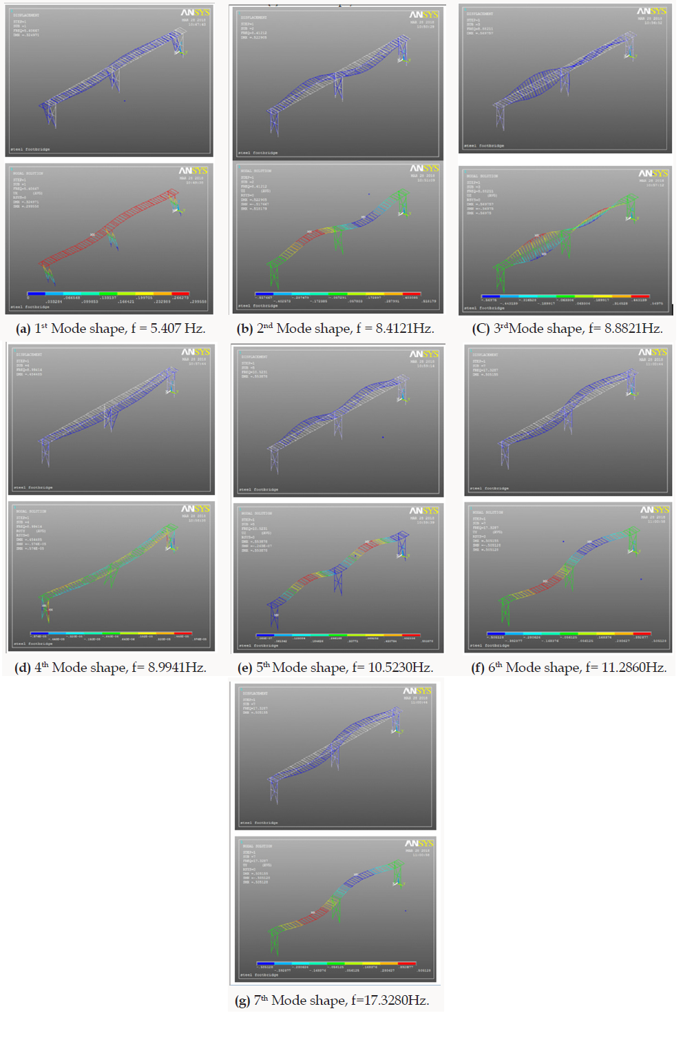
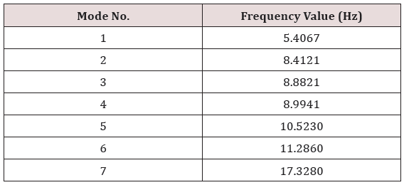
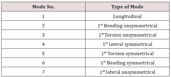
The results obtained from the modal analysis are the natural frequencies and the mode shapes of the adopted bridge structure. The natural frequencies values for first seven modes are listed in Table 1. The Type of mode shapes of the first seven corresponding natural frequencies is listed in Table 2 shown in Figure 2. The mode shapes, the maximum and minimum relative displacements in each direction of the first seven corresponding natural frequencies are shown in Figure 4a-g and it shows the first seven mode shapes of the adopted pedestrian bridge structure.
Code Standard
The Verification of the comfort criteria, according to Euro codes [5-7], should be performed if the structure has lateral or torsional modes of vibration lower than 2.5Hz and verti¬cal modes of vibration lower than 5Hz. The comfort criteria serves as recommended maximum levels of acceleration and it is up to the designer to determine whether it is necessary to make provisions in the design for damping after the structure is built [5-7].
Conclusion
The modal analysis of the pedestrian bridge using ANSYS APDL software was sufficient to identify seven modes below 20Hz. The first mode being fully coupled longitudinal with the first bending vibration frequency. The fundamental vertical frequency was identified as 8.4121Hz. The fundamental torsional mode was also observed uncoupled at 8.8821 Hz. The fundamental transverse frequency was identified as 8.9941Hz. The fundamental horizontal frequency was 17.3280Hz. The results show consistent of the bending, torsional and transverse modes. In modes 4, 5 and 6 the symmetrical exist. The results of the dynamic analysis showed that all frequency values exceed the standards according to euro code. The results of the dynamic analysis showed that all frequency values exceed the standards according to euro code. The range of vertical frequencies is between 8.4121Hz-11.2860Hz, the range of lateral frequency is between 8.9941Hz-17.3280Hz and the range of torsion frequencies is between 8.8821Hz-10.5230Hz. Where vertical and torsional frequencies values are exceed 682.4% for the lowest vertical frequency, while the ratio exceeded the greater vertical frequency is 1257.2%. As well as the override ratios for the lateral frequency is 2597.64%-5931.2%, while the torsional frequencies are in between 255.28%- 3209.2%. Therefore, the vibration of the studied bridge in this project is not in conformity with standards, as it exceeds the permitted values.
References
- B Ivan, A Marco, L Mathias (2014) Physically and Geometrically Nonlinear Vibrations of Thin Rectangular Plates. International Journal of Non Linear Mechanics 58: 30-40.
- G Polytech (2001) Basic of Experimental Modal Analysis. Polytec GmbH, Polytec Platz, Waldbronn Germany.
- A Chopra (2014) Dynamics of Structures-Theory and Applications to Earthquake. (4th edn), Prentice Hall, USA.
- ANSYS Inc, v-18, help guide.
- (2006) Footbridges: assessment of vibrational behavior of footbridges under pedestrian loading. Roads and Bridges Engineering and Road Safety, Paris, France.
- (2005) Eurocode 0: Basic of structural design. Appendix 2: Application for bridges, European Standard Norme.
- British Standards Institution (2003) UK National Annex to Eurocode 1: Action on structures-Part 2: Traffic loads on bridges, NA, London.

Top Editors
-

Mark E Smith
Bio chemistry
University of Texas Medical Branch, USA -

Lawrence A Presley
Department of Criminal Justice
Liberty University, USA -

Thomas W Miller
Department of Psychiatry
University of Kentucky, USA -

Gjumrakch Aliev
Department of Medicine
Gally International Biomedical Research & Consulting LLC, USA -

Christopher Bryant
Department of Urbanisation and Agricultural
Montreal university, USA -

Robert William Frare
Oral & Maxillofacial Pathology
New York University, USA -

Rudolph Modesto Navari
Gastroenterology and Hepatology
University of Alabama, UK -

Andrew Hague
Department of Medicine
Universities of Bradford, UK -

George Gregory Buttigieg
Maltese College of Obstetrics and Gynaecology, Europe -

Chen-Hsiung Yeh
Oncology
Circulogene Theranostics, England -
.png)
Emilio Bucio-Carrillo
Radiation Chemistry
National University of Mexico, USA -
.jpg)
Casey J Grenier
Analytical Chemistry
Wentworth Institute of Technology, USA -
Hany Atalah
Minimally Invasive Surgery
Mercer University school of Medicine, USA -

Abu-Hussein Muhamad
Pediatric Dentistry
University of Athens , Greece

The annual scholar awards from Lupine Publishers honor a selected number Read More...


