Lupine Publishers Group
Lupine Publishers
Menu
ISSN: 2637-4668
Research Article(ISSN: 2637-4668) 
Behavior of Normal and High Strength Reinforced Concrete Structures under Blast Loading Volume 2 - Issue 1
Mamoun A Alqedra*, Mohammed H Arafa and Mahmod Shaheen
- Department of Civil Engineering, The Islamic University of Gaza, Gaza, Palestine
Received: April 04, 2018; Published: April 17, 2018
Corresponding author: Mamoun Alqedra, Department of Civil Engineering, The Islamic University of Gaza, Gaza, Palestine
DOI: 10.32474/TCEIA.2018.02.000127
Abstract
Explosions near buildings can cause catastrophic damages and can cause injuries and loss of life to the occupants of these buildings. Experiments on explosions can be very expensive, dangerous and time consuming compared to simulation using suitable software. This study aims at modeling and analyzing a reinforced concrete structure under blast loading using finite element software LS-DYNA. The verification of the developed model was carried out by comparing the results of deflection and spalling with those obtained by reliable field experimental tests. The verification process indicated a close agreement between the obtained results of the model and those obtained from the actual experiments.
The material models of concrete and steel were carefully chosen to represent the actual behavior of both materials. The concrete and the steel reinforcement were modeled using LS-DYNA software as solid elements. Concrete was modeled using a continuous cap material model. The steel rebar was modeled using a material model with plastic deformation and strain rate effects. The penalty method was used for linking the concrete and the steel reinforcement joints. The blast was modeled using an empirical method that yielded a very good results. The developed model was utilized to study the effect of blast loading on a square 3 m single story building, where the blast was located in the middle of the building and 1 m away of the building side. The model was analyzed for 2 milliseconds. The effect of increasing concrete strength was studied. The effect of changing the blast location on the behavior of the structure was also investigated.
Keywords: Blast Loading, Finite Element Method, NSC, HSC, Reinforced Concrete, Structures
Abbreviations: NSC: Normal Strength Concrete, HSC: High Strength Concrete, FRP: Fiber Reinforced Polymers, NCHRP: National Cooperative Highway Research Program, ALE: Arbitrary Lagrangian Eulerian, LBE: Load Blast Enhanced, FEA: Finite Element Analysis
Introduction
A bomb explosion in or near a structure can cause disastrous damages to the structures and on the internal objects, and most importantly can cause injuries and loss of life to occupants due to direct blast or the structure collapse and fragments. Efforts have been made in the past few decades to develop methods to predict blast loading, predict the structural response to such extreme loads, and design the structure to withstand these loads and prevent progressive collapse [1,2,3]. An explosion is a result of a very rapid release of a large amount of energy; this release is caused by physical, chemical, or nuclear events [4]. When an explosion takes place, the expansion of the hot gases produces a pressure wave in the surrounding air called the shock wave, which moves away from the center of the explosion with the velocity of sound, and accompanied with a very high pressure in front of the wave. Such hot gases and high-pressure cause the wave to speed up to a certain level. After a short period of time, the pressure behind the front of the blast wave drops below the ambient pressure causing a partial vacuum in a negative phase. The front of the blast waves weakens as it progress far from the explosion center, and its velocity drops and so its peak pressure; It can be then treated as a sound wave [5,6].
Several investigations have been conducted to study the effect of explosions on buildings, and to simulate and model blast loads. Shugar 1992 used ABAQUS and DYNA3D (early version of LSDYNA) to model and analyze three different types of RC structures subjected to blast loads; a cylindrical missile test cell, flat slabs with variable shear steel, and a soil covered roof slab. The results of the analysis were considered accurate when compared to experimental tests. The concrete material models implemented in the software caused the simulation to terminate permanently. Remennikov [7] investigated and compared some of the available analytical and numerical techniques of predicting blast loads; the limitations of each method were identified. He simulated a simple case of a single building subjected to blast load using AUTODYN finite element software. The results of the analysis results were generally acceptable when compared to analytical methods.
Two ways of subjecting a structure to blast load were compared by Le Blanc [6] using LS-DYNA. The first was to apply a load model implemented in LS-DYNA keyword, and the second was a userdefined load based on empirical model created by.com Army [2]. The user defined load model for blast evaluation lead to more accurate and conservative results when used for surface blast loads. However, the load model in the LS-DYNA showed very good results when applied to model air blast loads.
A ground floor column of a multistory building was modeled and analyzed using LS-DYNA by Ngo T [5]. The modeling program consisted of two types of concrete; namely normal strength concrete (NSC) and high strength concrete (HSC). Further, two types of tie detailing, 400mm spacing for ordinary detailing and 100mm spacing for seismic detailing have been studied with decreasing the dimensions of the HSC Column. The analysis showed that the effect of shear reinforcement is a significant factor. The ultimate lateral displacement at failure increased by 50% when using 100mm ties. Eight doubly reinforced concrete panels with welded steel mesh were tested by Razaqpur [8]. Half of the specimens were additionally reinforced with Fiber Reinforced Polymers (FRP) on each face. The specimens are subjected to an explosive charge in the air, and then the tests data were recorded for each test specimen. Some of the specimens are modeled using software developed by the.com army based on empirical formulas from experiments, called CONWEP. The results obtained from the software analysis were in reasonable agreement with the experimental data.
A typical eight-story building subjected to blast loadings was investigated using the finite element software LS-DYNA by Almusallam [2]. The building was a RC framed structure with concrete core for lifting shafts designed with ACI-318 building code; the columns directly facing the blast were severely damaged due to fragmentation of concrete and rapture of steel bars and eventually lost their load bearing capacity. Due this loss, the gravity loads caused partial collapse of the structure. Borrvall and Riedel [9] defined a concrete model implemented in LS-DYNA and all its parameters. The defined concrete model was used to model a square RC plate and the rebar was modeled using beam elements along the mesh lines coupled to concrete. The results obtained from the analysis were acceptable compared to previous experimental results on a RC plate with the same parameters, with some comments needs further studying related to the behavior of the model in tension.
An experimental set-up for testing planner reinforced concrete elements under blast loads was designed by Morales Alonso [10], in which four slabs were tested in the same time in each detonation. The set-up consisted of a steel frame to support the four slabs, and the explosive charge was hanged in the middle of the frame to insure that the load distributed equally to the slabs. There were 12 slabs to test, six of them were normal strength concrete, and the other six were high strength concrete. The slabs failed due to tensile stresses on the rear slab side, and failed due to shear on the corners. Using the experimental data from the previous experiments, a numerical model was developed using the FEA software LS-DYNA. Two different material models were used to simulate concrete. The results of the analysis showed similarity using the two material models in the crack pattern. In the two cases, the numerical results are very similar to the experimental results.
The penalty method for connecting steel reinforcement to concrete was studied by Moutoussamy [11] for modeling several RC beams and frames with different reinforcement ratios. The results of the modeling were compared to calculated theoretical values of the deflection and resultant forces. For the modeled beams the values of yielding were close by 2% to 10% to the theoretical values. For the modeled frames, the numerical results for crack opening were close by 1% to theoretical results and the values of the yielding were close by 1% for normal case to 20% for under reinforcement case, this deviation was explained by the fact that the compressed section is too small so the stress distribution was not true. A reinforced concrete plates subjected to blast pressure wave was modeled by Tai [12] using LS-DYNA, and compared the results of different mesh sizes to results obtained from empirical equation. The comparison showed that finer meshing gives results that were more accurate. They also investigated the effects of different explosive amount, different reinforcement ratio and different standoff distances on the plate.
Puryear [13] used LS-DYNA to model and analyze a RC column with different parameters, such as charge weight, standoff distance and column geometry. The results of the analysis were compared to test data from a series of blast tests supporting National Cooperative Highway Research Program (NCHRP) [14]. The modeling and the analysis yields good results compared to NCHRP test results. Tabatabaei and Volz [15] modeled an experimental test in LS-DYNA to compare three different methods of simulation of blast loads on structures. These methods included empirical blast method, arbitrary Lagrangian Eulerian (ALE) method, and coupling of empirical and ALE Method. The test specimen was 184 × 184cm concrete panel reinforced to resist blast loads based on subjected to 36kg of TNT detonated at 168 cm above the center of the panel. The results of the analysis showed that, coupling of the empirical and ALE is the most suitable method.
Three concrete models implemented in (LS-DYNA) were studied by Wu [16]. The three material models were used in modeling and analyzing structures subjected to different dynamic loads. A comparison with available tests data showed the most suitable material among the three materials to represent concrete subjected to dynamic loads. Further, Magalhaes Pereira [17] tested three concrete material models implemented in LS-DYNA. A concrete bar subjected to a pulse load was modeled to study the three material models. The results obtained the most suitable material model to represent the concrete behavior.
Schwer [18] described several methods of including rebar in reinforced concrete and assessed the effectiveness of these methods through a comparative numerical example of concrete slab loaded in axial extension, under self-weight and subjected to air blast loading using LS-DYNA with comparison to experimental results. The concrete was modeled with solid elements and the reinforcement was modeled with beam elements. The described methods included smeared reinforcement, shared nodes and penalty methods. The analysis showed that when using any of the described methods provided acceptable results for the axial extension and self-weight load case. However, for the blast-load case, the smeared reinforcement was inadequate and the suitable method was the penalty method. Development of finite element analysis (FEA) software tools helps a lot in the field of dynamic loads and especially blast loads, because experimental tests of blast loads on structures are very expensive and dangerous. There are many FEA Software tools available for simulation of dynamic loads such as ABAQUS, DYNA3D, AUTODYN, ANSYS, LS-DYNA, etc. In this work, LS-DYNA software is used in modeling and analyzing a reinforced concrete structure with different concrete strength under blast loading.
Modelling of RC Structure Under Blast Loading
Material and Blast Loads Modeling
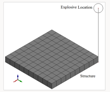
The concrete and the steel reinforcement were modeled using LS-DYNA software as solid elements. Concrete was modeled using a continuous cap material model which can be categorized as isotropic, plastic damage, and rate dependent model. It considers the Hooke’s law to describe elastic behavior. The damage and the plastic response of the materials are related according to Magalhaes Pereira [17] and Pereira 2013. The steel rebar was modeled using a material model with plastic deformation, strain rate effects, and failure. The penalty method was used for linking the concrete and the steel reinforcement joints. The blast load was simulated using an empirical method. This method is considered a simple less time consuming method as compared with other methods, while giving very good results [15]. In order to model the explosion load, the mass and coordinates of the explosion with respect to the structure were identified (Figure 1). The pressure from the explosion is computed empirically with CONWEP [3], referred to as LOAD_ BLAST_ENHANCED (LBE) and applied to the chosen structural surface.
Model Verification
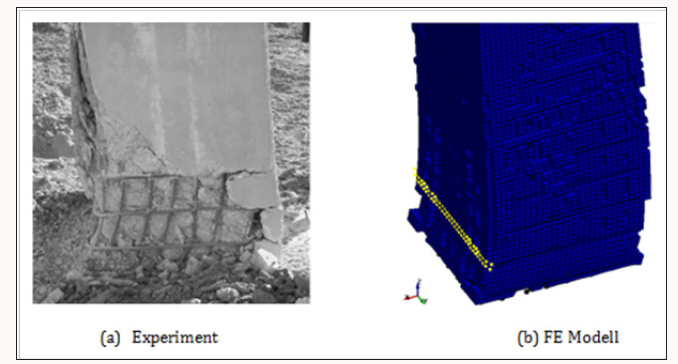
The developed model was verified by comparing the model analysis results with experimental results obtained by Williamson [14]. The data used in verification was from test number 9 from the report conducted with a column donated 3A designed to withstand low seismic loads. The column was a reinforced concrete rectangular with 30×30 in (762×762mm) dimensions. The maximum deflection of the model had a value of 73.96mm occurred at a height of 225 mm to 250mm above the bottom of the column, which was in a very good agreement when compared to 76.2mm obtained from the experimental tests. The shape of the deflection and spalling area for both numerical and experimental columns were nearly identical as shown in (Figure 2)
Effect of Concrete Strength under Blast Loading
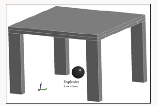
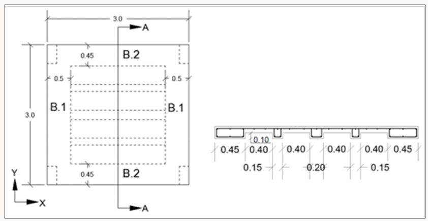
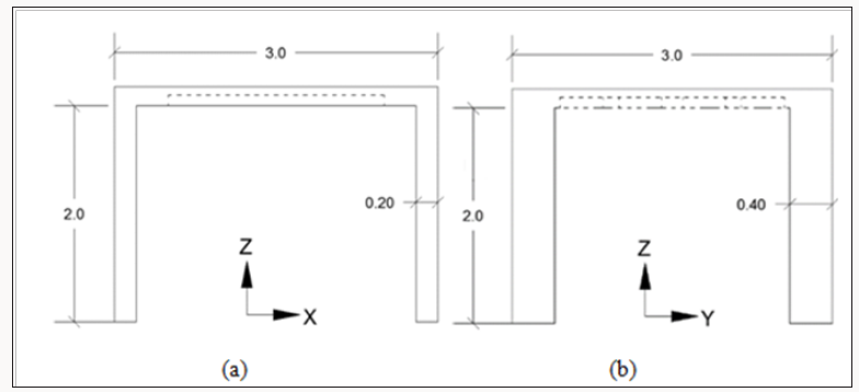
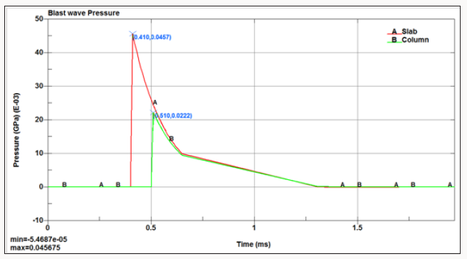
In order to study the effect of concrete strength on the behavior of the reinforced concrete structures under blast loading, a simple RC structure consists of 4 columns and one way ribbed slab (Figure 3), with normal and high concrete strength, was studied. The slab of 3m × 3m was designed according to ACI 318 [19] building code; It is a one way ribbed slab with a total thickness of 20cm (Figure 4). The slab are supported by two main beams (B1) of 50cm width, two secondary beams (B2) of 45cm width, in addition to two 15cm width ribs, and one 20cm middle rib. Each of the supported columns is 400mm by 200mm in cross section and 2m long (Figures 4 & 5). The structure was analyzed using LS-DYNA; two concrete strengths were considered, namely: normal strength concrete (NSC) of 29MPa and high strength concrete (HSC) of 58Mpa. The termination time of the analysis was set to 2 milliseconds (ms). The results of behavior of every part of the structure were recorded. The blast wave reached the slab first at time 0.4ms with a pressure of 45.7MPa, and then reached the columns at time 0.51 ms with a pressure of 22.2MPa (Figure 6).
Columns Stresses: The columns are the most important elements in the structure because they carry the whole structure. Destroying a column would cause a progressive collapse of the whole building. Due to the symmetry of the structure, only the results of one column were recorded. LS-DYNA uses positive sign for tension stresses and negative sign for compressive stresses. Table 1 shows the column maximum tensile stresses and compressive stresses of the normal and high strength concrete. The tensile stress of HSC is about 150% higher than that of the NSC. The stresses in the HSC don’t reach the concrete ultimate tensile stress, while it reaches the concrete ultimate tensile stress of the NSC. The compression stresses of HSC columns is about 176% in x-direction, 146% in y-direction, and 154% in z-direction than that of the NSC column. The maximum Von-Mises stress at the bottom of the column is recorded with a maximum value of 22.14MPa for the NSC and 24.6MPa for HSC at 2.0ms at the end of the analysis (Table 2).
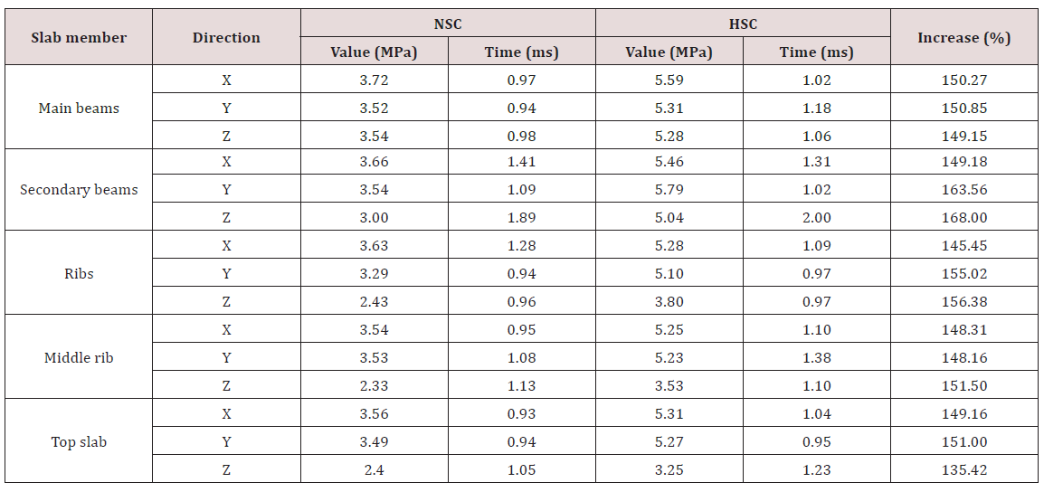
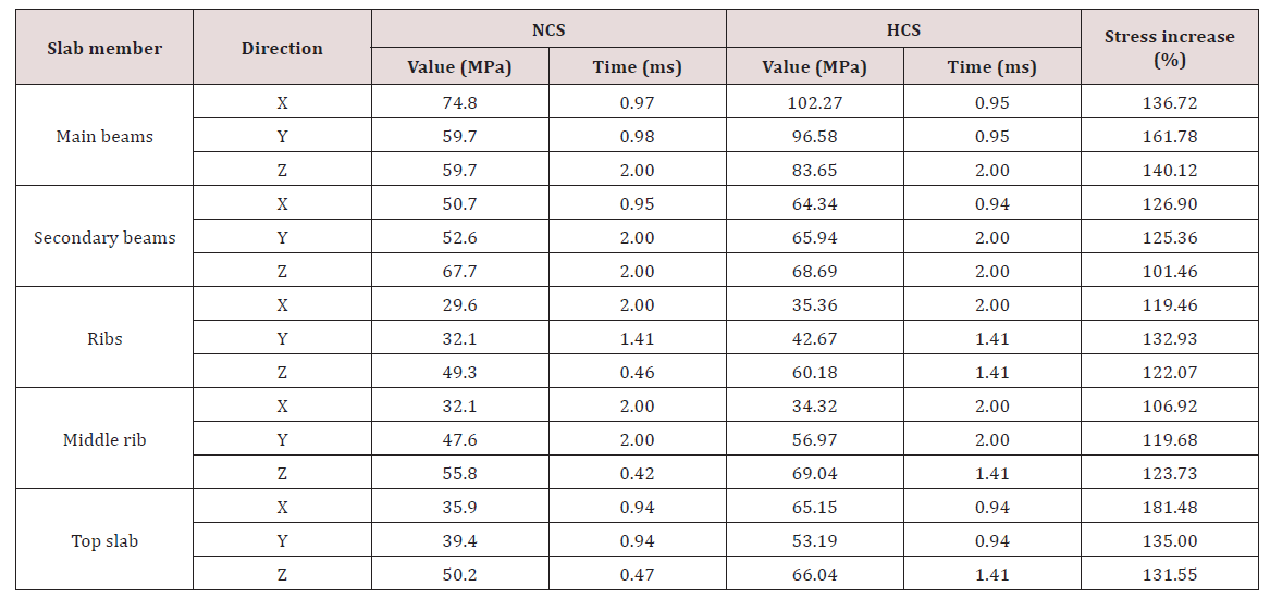
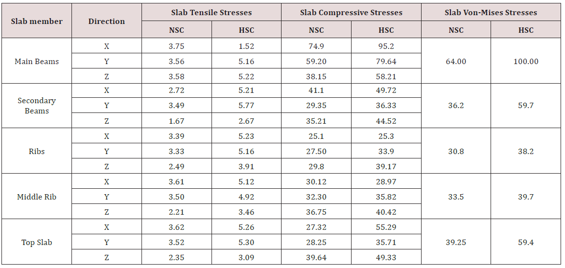
Slab Maximum Stresses: A slab maximum tensile and compressive stresses using HSC and NSC (Table 3 & 4). The maximum tensile stresses of the HSC are about 150% higher than that of the NSC in the main beams and slab ribs. The maximum compressive stresses of the HSC are about 150% higher than that of the NSC in the main beams and 125% in the slab ribs. Von-Mises stress values for different slab members made of HSC concrete strength were increased when compared to the corresponding values obtained from the slab members made of NSC concrete strength (Table 5). Table 6 shows a comparison of tensile, compressive stresses and Von-Mises stresses of NSC structure and HSC structure at same time of 1.0ms. It is clear that the stresses in case of HSC are higher than that of NSC.
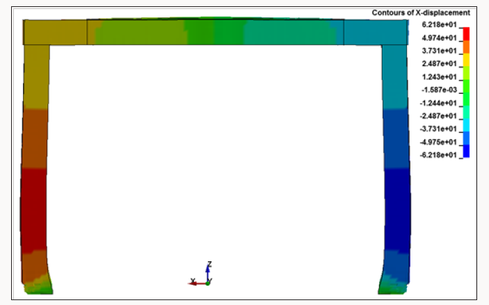
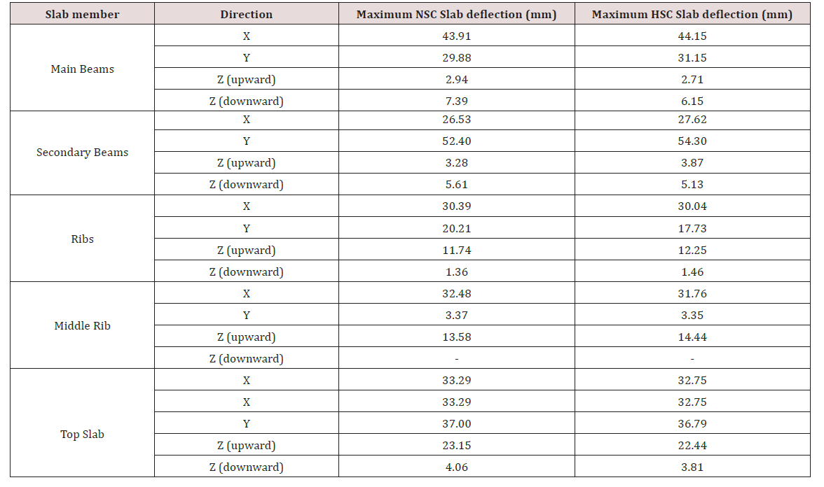
Structure Deformations: The analysis indicated that the columns gradually deformed to the outward until reaching its maximum deflection at the end of the analysis. Steel reinforcement prevented the destruction of the columns. The columns were spalled at the bottom near the supports. Figure 7 shows the contours of x-axis deflection and the spalling area of the columns at 2.0ms for NSC. The structure is symmetric about the y-axis so the values of deflection are also symmetric. A Comparison between the deflections of the columns made of NSC and NSC (Table 7). The high rate of the blast loading in the very short time of the analysis resulted in a close deflection values in all directions for all the structure’s members. Table 8 shows the results of deflection of the slab members of HSC strength concrete and the slab members of NSC strength concrete.
Effect of Charge Location
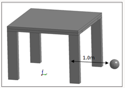
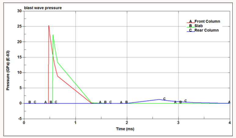
The original model of NSC was reanalyzed by relocating the explosion outside the structure through moving the explosion charge 2.5m away from the structure center in y-direction; which means 1.0m from the right columns centerlines (Figure 8). The new model was analyzed using LS-DYNA for 4.0ms. The blast wave reached the front columns first at 0.48ms with a pressure of 25.38MPa, then reached the slab at 0.56ms with a pressure of 22.36MPa, and then propagated through the structure to reach the rear columns at 2.62ms with a pressure of 1.33MPa, as shown in (Figure 9). The externally blasted structure was symmetrical only about y-axis, so the front members which are close to the explosion and the rear members which are far from explosion were exposed to different stresses. Table 9 shows the maximum tensile and compressive stresses in the front and rear columns. It is clear that the front columns reach the maximum tensile and compressive stresses before the rear columns.
The compressive stresses for the externally blasted slab members started increasing from the moment of the blast wave arrival to the members in different rates to reach the maximum values. The maximum compression stresses in the x-direction were recorded in the main beams. Further, the maximum stresses in the y- and z-direction were recorded in the front secondary beam. Compressive and tensile stresses for externally blasted slab members (Table 10). Von-Mises stresses in the externally blasted slab members started to increase from the moment of arrival of the blast wave and reach the maximum values at different times. The maximum Von-Mises stress was measured in the main beams. And the minimum Von-Mises stress was recorded in the rear secondary beam. Von-Mises stresses of the externally blasted slab members (Table 11). The externally blasted structure was deformed in the opposite direction of the explosion center (inward of the structure) of the y-direction. The maximum deflection of the slab members in all direction (Table 12).
Conclusion
In this work, LS-DYNA software is used in modeling and analyzing a reinforced concrete structure with different concrete strength under blast loading at two locations. The values of tensile stresses of the columns with the HSC strength concrete increased by about 150% when compared to those of NSC strength concrete under the same blast loading, while compressive stresses of HSC model increased by about 175% in x-direction, 146% in y-direction, and 154% in z-direction as compared to those obtained by the NSC model . The of Von-Mises stress of HSC compressive strength concrete column were 111% greater than that of the NSC.
The values of tension, compression, and Von-Mises stresses of the HSC slab members increased by about 150% as compared to those of the NSC. The values of deflection decreased slightly or almost unchanged in all directions for the slab members with HSC when compared to those of the slab members with NSC. Changing the explosion location to the outside the building changed the entirely behavior of the structure, the members close to the explosion had the higher deflection values and affected by higher stresses.
References
- Almusallam TH, Elsanadedy H, Abbas H, Ngo T, Mendis P (2010) Numerical analysis for progressive collapse potential of a typical framed concrete building. International Journal of Civil & Environmental Engineer 10(2): 40-46.
- US Army (1999) Structures to resist the effects of accidental explosions: Army TM5-1300, US Government Printing Office, pp. 1796.
- Hyde DW (1988) Microcomputer Programs CONWEP and FUNPRO, Applications of TM 5-855-1, Fundamentals of Protective Design for Conventional Weapons (User’s Guide).
- Baker W, Cox P, Westine P, Kulesz J, Strehlow R (1983) Explosion Hazards and Evaluation. Elsevier Scientific Publishing Company, USA.
- Ngo T, Mendis P, Gupta A, Ramsay J (2007) Blast loading and blast effects on structures-An overview. Electronic Journal of Structural Engineering 7(S1): 76-91.
- Le Blanc G, Adoum M, Lapoujade V (2005) External blast load on structures-Empirical approach. Paper presented at the 5th European LS Dyna Users Conference, France, UK.
- Remennikov AM (2003) A review of methods for predicting bomb blast effects on buildings. Journal of battlefield technology 6(3): 5.
- Razaqpur AG, Tolba A, Contestabile E (2007) Blast loading response of reinforced concrete panels reinforced with externally bonded GFRP laminates. Composites Part B: Engineering 38(5): 535-546.
- Borrvall T, Riedel W (2011) The RHT concrete model in LS-DYNA. Paper presented at the Proceedings of the 8th European LS-DYNA Users Conference, Strasbourg, UK.
- Morales Alonso G, Franco C, Angel D, Galvez Diaz Rubio F, Erice Echávarri B, et al. (2011) Analysis of the fracture of reinforced concrete flat elements subjected to explosions. Experimental procedure and numerical validation. Paper presented at the Anales de Mecánica de la Fractura, USA.
- Moutoussamy L, Herve G, Barbier F (2011) Qualification of Constrained_ Lagrange_In_Solid command for steel/concrete interface modeling. Paper presented at the Proceedings of the 8th European LS-Dyna Conference, USA.
- Tai Y, Chu T, Hu H, Wu J (2011) Dynamic response of a reinforced concrete slab subjected to air blast load. Theoretical and applied fracture mechanics 56(3): 140-147.
- Puryear J, Stevens D, Marchand K, Williamson E, Crane C (2012) ALE Modeling of Explosive Detonation on or near Reinforced-Concrete Columns. Paper presented at the 12th International LS-DYNA Users Conference, Detroit, USA.
- Williamson E, Bayrak O, Williams G, Davis C, Marchand K, et al. (2010) Blast resistant highway bridges: Design and detailing guidelines, Washington, USA.
- Tabatabaei Z, Volz J (2012) A comparison between three different blast methods in LS-DYNA: LBE, MM-ALE, Coupling of LBE and MM-ALE. Paper presented at the 12th International LS-DYNA Users Conference, USA.
- Wu Y, Crawford JE, Magallanes JM (2012) Performance of LS-DYNA concrete constitutive models. Paper presented at the 12th International LS-DYNA users conference, USA.
- Magalhaes Pereira L, Weerheijm J, Sluys L (2013) Damage prediction in a concrete bar due to a compression and tension pulse: A comparison of the K&C, the CSCM and the RHT material models in LS-DYNA. Paper presented at the 15th ISIEMS Conference: International Symposium on the Interaction of the Effects of Munitions with Structures, Potsdam, Germany.
- Schwer L (2014) Modeling rebar: the forgotten sister in reinforced concrete modeling. Paper presented at the 13th International LS-DYNA Users Conference.
- ACI 318 (2014) ACI 318-14 Building Code Requirements for Structural Concrete and Commentary (Metric), American Concrete Institute, USA.

Top Editors
-

Mark E Smith
Bio chemistry
University of Texas Medical Branch, USA -

Lawrence A Presley
Department of Criminal Justice
Liberty University, USA -

Thomas W Miller
Department of Psychiatry
University of Kentucky, USA -

Gjumrakch Aliev
Department of Medicine
Gally International Biomedical Research & Consulting LLC, USA -

Christopher Bryant
Department of Urbanisation and Agricultural
Montreal university, USA -

Robert William Frare
Oral & Maxillofacial Pathology
New York University, USA -

Rudolph Modesto Navari
Gastroenterology and Hepatology
University of Alabama, UK -

Andrew Hague
Department of Medicine
Universities of Bradford, UK -

George Gregory Buttigieg
Maltese College of Obstetrics and Gynaecology, Europe -

Chen-Hsiung Yeh
Oncology
Circulogene Theranostics, England -
.png)
Emilio Bucio-Carrillo
Radiation Chemistry
National University of Mexico, USA -
.jpg)
Casey J Grenier
Analytical Chemistry
Wentworth Institute of Technology, USA -
Hany Atalah
Minimally Invasive Surgery
Mercer University school of Medicine, USA -

Abu-Hussein Muhamad
Pediatric Dentistry
University of Athens , Greece

The annual scholar awards from Lupine Publishers honor a selected number Read More...


