
Lupine Publishers Group
Lupine Publishers
Menu
ISSN: 2637-4668
Research Article(ISSN: 2637-4668) 
Analytical Modelling of the Historical Diyarbakir Karasu Bridge for its Ability to Carry Civil and Military Transport Volume 1 - Issue 4
Mustafa Kaya*
- Department of Engineering, Aksaray University, Turkey
Received: February 15, 2018; Published: March 01, 2018
Corresponding author: Mustafa Kaya, Department of Engineering, Aksaray University, Turkey
DOI: 10.32474/TCEIA.2018.01.000118
Abstract
In this study, the Karasu Bridge dating back to the Roman period was examined to determine whether it was suitable to carry heavy commercial and military vehicles in special circumstances. An analytical model of this bridge was created using an ANSYS program based on finite elements. On the bridge model, linear and non-linear static analyses were performed first according to the heavy vehicle loads stated in AASHTO (American Association of State of Highway Transportation Officials) then in the second stage heavy military vehicles loads were simulated. As a result of the analysis, even though linear crushes were observed at the areas where the side walls of the bridge are fixed to the piers, it was seen that Karasu Bridge was capable of safely carrying the vehicle load as stated in AASHTO and military tanks in a safety way transport.
Keywords: Historical arch bridges; Finite element method; Nonlinear analysis
Introduction
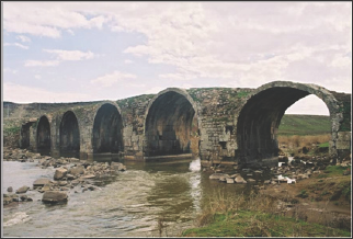
Turkey has seen many different civilizations, and consequently, today, there are many historical buildings such as religious premises, viaducts and bridges. One of these important artifacts is the Karasu Bridge which crosses the Devegefidi river which is located 12km from Diyabakir -on the road to Ergani road (Figure 1). There is no specific information on the Karasu Bridge regarding the construction date however, taking the architectural features of the bridge into consideration, it is estimated that the bridge dates back to the Roman period. The bridge is mainly constructed in half circle arches and the remainder of the construction is based on a rectangular prism of the stones. Various researches have been carried on historical buildings. For example, Hagia Sophia, in Istanbul was analyzed by Ozkul and Kuribayashi [1] using a linear finite element model.
Figure 1: View of Karakopru direction from downstream.
The dynamic characteristics of the Hagia Sophia were obtained using the Wilson-0 method and also the ground motion data to understand its general structural behavior in the future earthquakes. Mele et al. [2] analyzed a basilica-type church in order to assess its structural behavior and seismic vulnerability. For this purpose, they used 3D static and dynamic linear analyses, and 2D nonlinear pushover analysis. The current structural state of the Basilica of Pilar, Zaragoza, Spain was investigated by Romera et al. [3]. The behavior of brick masonry, the main material used in the construction, was simulated first with linear elastic isotropic models and later with several non-linear isotropic models including brittle behavior in tension and plastic behavior in compression. Betti and Vignoli [4] applied the static and dynamic non-linear analysis to a basilica- type masonry church in order to assess its structural behaviour and its seismic vulnerability. Betti and Vignoli [5] also applied the static and dynamic nonlinear analysis to a Romanesque masonry church in order to assess its behavior and seismic vulnerability. The Qasr al-Bint historical monument in Jordan has been concerned by Bani-Hani and Barakat [6]. Dynamic finite element analyses were performed on both the existing monument in its current condition and for the proposed restoration. Experimental and numerical analysis of historical buildings were undertaken by Lourenfo [7].
This study is fully detailed, including the aspects of the survey, advanced numerical analysis, diagnosis, and strengthening. Makarios and Demosthenous [8] investigated the seismic behavior of historical structures. They used a representative numerical model of a typical traditional building from a series of examined models. They employed a dual bearing system, using, as the base excitation, the two horizontal recorded components of the main earthquake ground motion. A masonry tower called Torre Sineo was analysed by Carpinteri et al. [9]. In the first part of this study nondestructive evaluation techniques with thermographic analysis were adopted to assess the present condition of the tower. In the second part of the study, in order to assess the behavior of the tower, the results from a nonlinear analysis are presented. The seismic analysis and vulnerability of historical city centers were undertaken by Ramos and Lourenfo [10]. The finite element method has been adopted for a number of different analyses, introducing non-linear behavior of the materials.
Toth et al. [11] investigated the effect of backfill on the multispan masonry arch. This multi-span type of masonry arch was modelled and the original backfill material was replaced with different sands and clays then service loading conditions were applied. Zeman et al. [12] analysed the Charles Bridge in Prague using non-linear three-dimensional and mechanics-oriented simulations of selected bridge segments. Studies on the Tanaro Bridge were carried out by Brencich and Sabia [13]. A comparative characterization of the brickwork was performed by means of compressive tests on cylinder flat jacks, while other dynamic tests, including the identification of natural frequencies have were carried out on the bridge. Data from the material testing were used to setup FEM models, so that comparison could be made between the dynamic tests and the FEM results.
In order to prevent damage Karasu Bridge is closed to vehicular traffic. However, bridges closed to vehicles traffic also suffer damage to due to insufficient covering and drainage, the existence of vegetation and biological colonization and diminishing stream beds. Bridges that are open to traffic are periodically maintained by the municipalities at the city centers and by the General Directorate of Highways out of the center. In this study, the Karasu Bridge was examined to determine whether it could carry the test vehicle loads stated in AASHTO and military transport ( in this case Leopard 2A4 Turkish army tanks) in specific circumstances such as war and post disaster rescue services. The bridge was modelled using finite element based ANSYS program. Linear and non-linear static analyses of the bridge, whose analytic model was formed, were performed under the above stated loads. ANSYS [14] finite element software is used for this purpose.
Geometry and Construction Materials of Karasu Bridge
The Karasu Bridge was constructed with a traditional masonry technique comprising six arches which exceed the water it passes over, and its surface slopes from the centre towards the two ends. The length of the bridge is 78.23m and its width is 7.70m. the bridge is made up of six arches. The total height of the bridge is 5.14m at the left end 5.65 m at the right end, and in the middle of the span the height is 6.24m.
The main construction material of the bridge is the porous and non-porous Karacadag basalt stone obtained in the region. Porous basalt stone is used for the over flooring, non-porous for the arches, porous and non-porous for the piers. The area between the sidewalls of the bridge is filled with a lime mortar [15]. Descriptions of the materials are given below.
Basalt stone
Karacadag Basalt resists water absorption, freezing and friction. It is readily available and has been widely used in various constructions over the centuries. The compressive strength of the basalt stone was determined by performing compressive strength test. The compressive strength of the non-porous basalt was determined to be 89.10 MPa, and the compressive strength of the non-porous basalt was 51.76 MPa. Tested by the Brazilian splitting test, the tension strength of the non-porous basalt was determined to be 13.94 MPa, and the tension strength of the porous basalt was 7.16 MPa. The unit weight of the non-porous Karacadag basalt was calculated as 2.85 x10⁻⁵N/m3, and the unit weight of the porous Karacadag basalt was calculated as 2.28 x10⁻⁵N/m3. Table 1 presents the compressive strength, tension strength, modulus of elasticy, poisson ratio and unit weights of the porous and non- porous basalt stones.
Table 1: Material properties

Grout mortar
The mortar consists of a well mixture which has a good contact between the agrega and the mortar. 20 ~25 % of the mortar is brick pieces and dust, 10% is sand stone, 20% is mixed agrega, and the remaining is bone colored agrega whose origin is not known [15,16].
Finite element modelling
The Karasu Bridge was analytical modelled with the ANSYS finite element program [14]. In the analytical model, model size, material properties, and boundary condition were parallel to the virtual bridge.
Modelling of materials
Figure 2: Necessary parameters for the multilinear isotropic modeling of materials.
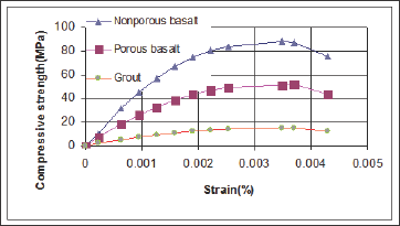
Since the behaviors of the basalt stone and the mortar show similar features to concrete, those materials were modelled using the Solid65 element used in modelling the concrete in ANSYS program. The strain-stress curves of material are given in Figure 2.
In this study, the Hognestad concrete model was used to model of Basalt stones and grout [17]. The stress-strain values obtained from this model were used in the definition of the multilinear isotropic model. In addition, the Willam-Warnke failure model [18] was used in the definition of the stone and grout.
Modelling of the karasu bridge
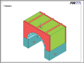
The major elements of the bridge are the arches, piers and the sidewalls. The mortar is only a minor element, transferring the loads affecting its surface to the arches. For this reason, since it was not appropriate to complete the analyses because of the crushes and cracks of the mortar, the mortar was accepted to be linear elastic in order to ignore the crushes and cracks occurred. Non-porous basalt stone was used for the arches and piers of the Karasu Bridge, and porous basalt stone for the sidewalls of the bridge. In the analytical modelling of the Karasu Bridge with ANSYS program, basalt stone was defined as the main construction material of the bridge and the mortar for the over surface of the arches was defined as the Solid 65 [14] element. The features of the porous and non-porous basalt stone are given in Table 1. In the bridge, the plates placed under the wheels of the heavy vehicles and under the treads of the tank during loading were defined as a Solid45 [14] element. While forming free mesh for the sidewalls and the motar, mapped mesh was formed for the arches and the element under the plates. The volumes of the models are given in Figure 3.
Figure 3: Volumes of the Karasu Biridge under heavy truck weight.
Loading of the Karasu Bridge
In the first stage of the study, an analysis was performed for the Karasu Bridge in order to determine whether the civil vehicles such as trucks and could pass over the bridge. In the second stage an analysis was performed to determine whether the military vehicles could pass over the bridge when needed. In the first stage of the loading, a S30H24 heavy vehicle load as stated in AASHTO [19] was applied to the first span of the bridge. In this loading, it was supposed that two vehicles coming from the opposite directions were on the bridge. In this stage; all the materials were accepted to be linear elastic in the for both of the loading conditions. In the second stage, the first span of the bridge was loaded with the 62.3 ton weight of the Leopard 2A4 tanks which used by the Turkish armed forces. The tread length of the tanks is 7.7 m with a width of 3.7m.
The weight of the tank was transferred to the floor through two sections of plates with a width of 0.5 m. It was supposed that the tanks on the bridge were moving in the same direction and there was a tank at every span. In this stage; the materials used in the piers of the bridge, arches and the sidewalls were accepted to be non-linear and the mortar, and the materials placed under the wheels of the trucks and the treads of the tanks were accepted to be linear elastic. The load was applied beginning with 0 up to tank weights and heavy vehicle weights. The maximum stresses, crushes and cracks occurring on the bridge under these loadings were determined.
Results and Discussion
Since and the spans of the Karasu Bridge were nearly equal to each other and the performed loading was in vertical direction only the first span of the bridge was modelled analytically in the analyses performed in accordance with the tank weights and heavy vehicle loads (H30S24). From the results obtained from the linear and non-linear analyses, the values of the maximum compressive and tension stresses were given where the shear stress is zero.
Analysis under military vehicle loading
Figure 4: Compressive stress status of Karasu Bridge model under military vehicle weight (Nonlinear analysis).
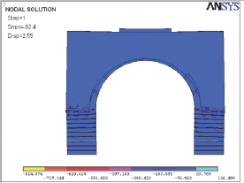
In the linear and non-linear static analyses performed under tank load at the Karasu Bridge, the maximum compressive stresses occurred at the locations where the sidewalls of the bridge were fixed to the piers of the bridge. The maximum compressive stress was seen in the linear analysis of the bridge under the tank load was -80.12MPa. In the non-linear analysis of the bridge, the maximum compressive stress, occurring between the sidewalls of the bridge and the piers of the bridge under the same load was -82.41MPa (Figure 4). The compressive stress obtained from the non-linear analysis was 59% more than the compressive strength of the porous basalt stone of the bridge sidewalls. In the analyses performed under the tank load, maximum tension stress occurred at the lower edges of the sidewalls of the bridge, outer edges of the arches and at the connection points of the upper edges of the piers of the bridge.
The maximum tension stress observed in the linear analysis of the bridge was 23.29MPa, and as for the non-linear analysis of the bridge the maximum tension stress occurring in the same area was 27.71MPa (Figure 5). The tension stress obtained in the non-linear analysis was 283% more than the tension strength of the porous basalt stone and 95% more than the tension strength of the non-porous basalt stone. In the linear analysis performed under the tank load at the first span of the Karasu Bridge, 2.24 mm of displacement was observed and in the non-linear analysis, 2.55 mm of displacement was observed in the middle of the span. In the non-linear analysis of the first span of the Karasu Bridge under the tank load, crushing was observed between the bottom edges of the sidewalls of the bridge where the maximum compressive straining was observed and the upper edges of the piers of the bridge. Furthermore, cracks were observed at the bottom ends of the outer edges of the arches where the tension stress was maximum, at the upper edges of the piers of the bridge, and at the joining areas of the bottom parts of the sidewalls (Figure 6).
Analysis of the karasu bridge under H30S24 truck load
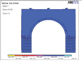
In the analyses of the Bridge under the H30S24 vehicle load as stated in AASHTO, the maximum compressive stress occurring in the areas where the sidewalls of the bridge were fixed to the piers of the bridge under the tank weight. In the linear analysis performed under H30S24 vehicle load, the maximum compressive stress occurring at the first span of the bridge was - 81.40MPa, and in the non-linear analysis performed under the same load, the maximum compressive stress occurring at the first span of the bridge was - 81.60MPa (Figure 7). The compressive stress occurring in the nonlinear analysis of the Karasu Bridge under the H30S24 vehicle load as stated in AASHTO was seen to be 25% more than the compressive endurance of the porous basalt stone of the bridge sidewalls.
Figure 5: Tension stress status of Karasu Bridge model under military vehicle weight (Nonlinear analysis).
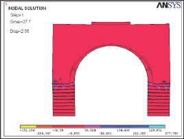
Figure 6: Crack and crushing patern of Karasu Bridge under military vehicle loading.
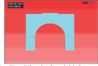
Figure 7: Compressive stress status of Karasu Bridge model under heavy truck weight ( Nonlinear analysis).
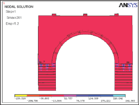
It was observed in the linear and non-linear analyses performed under the heavy vehicle loads that the maximum tension stresses occurring at the first span of the Karasu Bridge were at the bottom edge of the sidewall of the bridge, and at the connection point of the outer side of the arch and the upper edge of the pier. The maximum tension stress occurred in the linear analysis performed under heavy vehicle loads was 22.92MPa and the maximum tension stress in the non-linear analysis performed under the same load was 26.18MPa (Figure 8). The maximum tension stress occurring in the non-linear analysis performed under H30S24 heavy vehicle loads was 226% more than the tension strength of the porous basalt stone according to the non-linear analysis and 66% more than the tension strength of the non-porous basalt stone. In the linear analysis performed in the middle of the first span of the Karasu Bridge. Crushes were seen at the bottom edge of the sidewalls and piers of the bridge where the compressive stress was high, and cracks were observed at the connection points of the sidewalls of the bridge, outer edges of the arches and bridge piers where the tension stresses were at under the heavy vehicle loads 2.74mm displacement was observed maximum. and in the non-linear analysis, 3.13mm displacement was observed in the middle of the first span of the Karasu Bridge. Crushes were seen at the bottom edge of the sidewalls and piers of the bridge where the compressive stress was high, and cracks were observed at the connection points of the sidewalls of the bridge, outer edges of the arches and bridge piers where the tension stresses were at maximum.
Figure 8: Tension stress status of Karasu Bridge model under heavy truck weight (Nonlinear analysis).
Conclusion
The linear and non-linear static analyses of the Karasu Bridge were performed according to the weight of the Leopard 2A4 tanks owned by the Turkish armed forces and H30S24 heavy vehicle loads stated in AASHTO. In both analyses for each of the loading conditions, it was seen that the stress and strain values obtained from the non-linear analyses for the same loading condition was higher than the values obtained from the linear analyses. When the results of the non-linear static analysis performed according to the weight of the tank was considered, the compressive stresses occurred were 9% less than the compressive strength of the non- porous basalt stone used in the major elements of the bridge; the arches and piers which were, and 25% more than the compressive stress of the porous basalt stone used in the sidewalls of the bridge.
The tension stress occurring in the non-linear analysis performed according to the proposed weight of the tank which crosses the Karasu Bridge was 66% more than the tension strength of the non-porous basalt stone and 226% more than the tension strength of the porous basalt stone. The compressive stresses occurring in the non-linear analysis of the Karasu Bridge performed under H30S24 heavy vehicle load as stated in AASHTO was 25% more than the compressive strength of the porous basalt stone of the sidewalls of the bridge, and 28% less than the compressive strength of the non-porous basalt stone of the arches and piers of the bridge. The tension stress occurring in the non-linear analysis performed under H30S24 heavy vehicle loads was 212% more than the tension strength of the porous basalt stone and 62% more than the tension strength of the non-porous basalt stone.
When the results obtained from the linear and non-linear analyses of the Bridge were considered, even though the maximum compressive stresses were greater than the compressive strength of the porous basalt stone of the sidewalls of the bridge, it was smaller than the compressive stress of the non-porous basalt stone of the arches and piers of the bridge. Therefore, the fact that the compressive stresses being greater than the compressive strength of the material (porous basalt) of the sidewalls of the bridge do not have a negative effect on the carrying power of the bridge. However, it causes crushes at the bottom edges of the wall where the sidewalls of the bridge are fixed onto the piers of the bridge. Those crushed parts may need repairing at certain intervals. As a result of the linear and non-linear analyses of the analytical model which was created, it has been concluded that the historical Karasu Bridge, can be used by vehicles such as military tanks, personnel transport and trucks carrying heavy loads in special circumstances such as war and after natural disasters. However, continuous heavy load use is not recommended.
References
- Ozkul TA, Eiichi Kuribayashi E (2007) Structural characteristics of Hagia Sophia: II- A finite element formulation for dynamic analysis. Building and Environment 42(5): 2100-2106.
- Mele E, De Luca A, Giordano A (2003) Modelling and analysis of a basilica under earthquake loading. Journal of Cultural Heritage 4(4): 355-367.
- Romera LE, Hernández S, Reinosa JM (2008) Numerical characterization of the structural behaviour of the Basilica of Pilar in Zaragoza (Spain). Part 1: Global and local models. Advances in Engineering Software 39(4): 301-314.
- Betti M, Vignoli A (2008) Assessment of seismic strength of a basilica- type church under earthquake loading: Modelling and analysis. Advances in Engineering Software 39(4): 258-283.
- Betti M, Vignoli A (2008) Modelling and analysis of a Romanesque church under earthquake loading: Assessment of seismic strength. Engineering Structures 30(2): 352-367.
- Bani Hani K, Samer Barakat S (2006) Analytical evaluation of repair and strengthening measures of Qasr al-Bint historical monument- Petra, Jordan. Engineering Structures 28(10): 1355-1366.
- Lourenço PB (2006) Recommendations for Restoration of Ancient Buildings and The Survival of a Masonry Chimney. Construction and Building Materials 20(4): 239-251.
- Makarios T, Demosthenous M (2006) Seismic response of traditional buildings of Lefkas Island, Greece. Engineering Structures 28(2): 264278.
- Carpinteri A, Invernizzi S, Lacidogna G (2005) In situ damage assessment and nonlinear modelling of a historical masonry tower. Engineering Structures 27(3): 387-395.
- Ramos LF, Lourenço PB (2004) Modelling and vulnerability of historical city centers in seismic areas: a case study in Lisbon. Engineering Structures 26(9): 1295-1310.
- Tôth AR, Orban Z, Bagi K (2009) Discrete element analysis of a stone masonry arch. Mechanics Research Communications 36(4): 469-480.
- Zeman J, Novâk J, Sejnoha M, Sejnoha J (2008) Pragmatic multi-scale and multi-physics analysis of Charles Bridge in Prague. Engineering Structures 30(11): 3365-3376.
- Brencich A, Sabia D (2008) Experimental identification of a multispan masonry bridge: The Tanaro Bridge. Construction and Building Materials 22(10): 2087-2099.
- ANSYS Users (1992) Manual for Revision 5.0, Vol. I, Procedures, Swanson Analysis Systems, Inc., Houston, USA.
- Halifeoglu M, Dalkiliç N (2002) Development Process of Basalt From The Ancient Times to Our Days and Its Usage Areas In Today's World. The First National Construction Material Congress 9-13: 570-579.
- Kahveci AE (2008) A Study on The Examination of The Usage of Basalt Stone As A Construction Material In Diyarbakir Region, Thesis of Master's Degree, Süleyman Demirel University, Isparta, Turkey .
- Hognestad EA (1951) Study of Combined Bending and Axial Load in R.C. Members. Universty of Illinois Engineering Exp Sta Bull 399(2): 36-57.
- Willam KJ, Warnke EP (1974) Constitutive Model for Triaxial Behavior of Concrete. International Association of Bridge and Structural Engineering: 174-198.
- American Association of State Highway and Transportation Officials (AASHTO) (2010) American Association of State and Highway Transportation Officials.

Top Editors
-

Mark E Smith
Bio chemistry
University of Texas Medical Branch, USA -

Lawrence A Presley
Department of Criminal Justice
Liberty University, USA -

Thomas W Miller
Department of Psychiatry
University of Kentucky, USA -

Gjumrakch Aliev
Department of Medicine
Gally International Biomedical Research & Consulting LLC, USA -

Christopher Bryant
Department of Urbanisation and Agricultural
Montreal university, USA -

Robert William Frare
Oral & Maxillofacial Pathology
New York University, USA -

Rudolph Modesto Navari
Gastroenterology and Hepatology
University of Alabama, UK -

Andrew Hague
Department of Medicine
Universities of Bradford, UK -

George Gregory Buttigieg
Maltese College of Obstetrics and Gynaecology, Europe -

Chen-Hsiung Yeh
Oncology
Circulogene Theranostics, England -
.png)
Emilio Bucio-Carrillo
Radiation Chemistry
National University of Mexico, USA -
.jpg)
Casey J Grenier
Analytical Chemistry
Wentworth Institute of Technology, USA -
Hany Atalah
Minimally Invasive Surgery
Mercer University school of Medicine, USA -

Abu-Hussein Muhamad
Pediatric Dentistry
University of Athens , Greece

The annual scholar awards from Lupine Publishers honor a selected number Read More...


