Lupine Publishers Group
Lupine Publishers
Menu
Research ArticleOpen Access 
Low-Cost Scanning Using a Smartphone for Prosthetics Applications Volume 2 - Issue 2
Sean Cullen1*, Ruth Mackay1, Amir Mohagheghi2 and Xinli Du1
- 1Department of Mechanical and Aerospace Engineering, College of Engineering, Design and Physical Sciences, Brunel University London, UK
- 2Division of Sport, Health & Exercise Sciences, College of Health, Medicine and Life Sciences, Brunel University London, UK
Received: November 11, 2022 Published: November 23, 2022
Corresponding author: Ho Chih Cheng, Department of Information Technology, Ling Tung University, Taiwan
DOI: 10.32474/JBRS.2022.02.000133
Abstract
Smartphone photogrammetry can provide a basis for low cost and accessible digital scanning in the prosthetics industry. This will provide a host of benefits to prosthetists and amputees, including faster manufacturing time and a digital record of the socket. This paper therefore aims to determine an optimal technique for scanning both residuum and socket casts using smart phone photogrammetry, through the use of quantitative digital twin comparisons and 3D printing. An optimal photographic technique was identified using genetic algorithms. The chosen method achieved the highest accuracy of 99.65% and 99.13% in surface area and volume respectively, requiring only twenty-six photos from three radial positions. The method presented takes less than ten minutes to capture, however, it can take hours to mesh the photos depending on the software used. The method is within clinical limits for accuracy, requires minimal training, and is non-destructive so can be used in conjunction with existing workflows.
Keywords: Prosthetics; Sockets; scanning; photogrammetry; low cost; digital twin; genetic algorithms
Introduction
Conventionally, lower limb prosthetic sockets are fabricated using hand casting and rectification techniques. Despite digital design and fabrication techniques and their benefits being explored for some time in the literature, traditional techniques are still dominant [1-6]. Socket fit is critical to user comfort, and good methods of digitizing patient data are therefore crucial for the success of digital socket manufacturing [7-9]. Many devices can be used to achieve accurate socket digitization such as MRI scanners, laser scanners, and optical scanners [10-14]. These scanners are costly and often require specialised training, hindering their use in limb centers.
D Solav. et al, introduced a low-cost method for residuum scanning using an array of digital cameras which was further developed upon by M Barreto. et al achieving an error of <1.93mm scanning a 3D printed residuum mould [15,16]. Whilst low cost, this method did require a specialised cylindrical camera array which introduces barriers to its inception in clinical practice. By contrast, smartphone photogrammetry offers a method for digitization without the requirement for specialised equipment. Smartphone photogrammetry was first introduced by A. Hernandez and E. Lemaire for scanning socket interiors [17]. However similar work by the present authors noted inaccuracies in scanning internal volumes near the base of the socket wall when using photogrammetry, because of the limited number of angles at which the photographs were taken [18]. The inaccuracies noted would potentially lead to reproduced sockets with inferior fit, and reduced comfort for amputees. For positive socket moulds however, there are no restrictions from the imaging perspective.
Given hand techniques are still dominant in the prosthetics industry, digital techniques would be better integrated with current practice if compatible with the current workflow, namely around the socket rectification and final manufacturing stage. The artisan skill clinicians perfect through years of practice with hand rectification is not necessarily transferable to the digital space. This could be the reason that when surveyed by the American Board of Certification for Orthotists and Prosthetist in 2014, only 23% of prostheses were fabricated using Computer Aided design (CAD) and Computer Aided Manufacturing (CAM) techniques [19]. Scanning of rectified casts, as explored in this paper, may be better suited to the current industry environment when compared to direct limb scanning. Because scanning is a non-destructive process, a scan can be taken of a rectified mould acting as a ‘back up’ prior to its destruction during the socket lamination process. Alternatively, a socket could be directly produced from the scan data, using either centralized manufacturing facilities or 3D printing [20,21]. It should be noted that work by J Sanders et al. queried the accuracy and quality of sockets produced from centralized fabrication facilities [22]. Comparatively, 3D printed sockets may be more accurate, but limited research has been conducted on the strength of these sockets [23,24].
Despite the authors prior work showing photogrammetry was not a suitable scanning method for sockets, the same inherent constraints are not present when scanning positive residuum casts or socket moulds. The relative accessibility of photogrammetry and the simplicity of the technique could help bridge the industry gap hindering digital techniques, however photographic techniques and their associated accuracy for this use have not been explored in the literature. This paper therefore aims to determine an optimal technique for scanning both the residuum and socket casts using smart phone photogrammetry.
The basic methodology and evaluation technique, namely genetic algorithms and 3D printed digital twin models, from the authors’ previous paper were chosen as they showed merit and were simple to implement.
Methodology
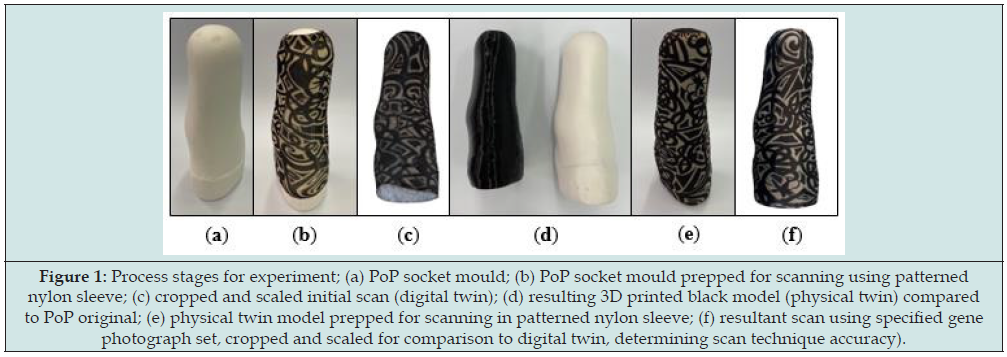
A male rectified socket mould was taken from an existing socket using Plaster of Paris (PoP). The socket was destroyed in this process to preserve the mould. The cast was covered in an unbranded printed nylon sleeve, placed on a pedestal, and photographed with random camera positions, using an iPhone 12 (Apple, CA, USA) on automatic settings. The nylon sleeve was unbranded with a thickness of 0.17±0.01mm across the fabric with a brim thickness of 0.40±0.03mm. Using Autodesk ReCap (Autodesk, CA, USA) a 3D mesh was created from the images, which was cropped and scaled using the measure height of the cast to create the digital twin reference model. The model was 3D printed using a Creality CR-10 (Creality, Shenzhen, China) with a nozzle size of 0.8mm and a 0.36mm layer height, forming the physical twin. Some material was trimmed from the bottom of the model to reduce the print time; however, the socket profile was left intact. This process is highlighted in Figure 1.
Figure 1: Process stages for experiment; (a) PoP socket mould; (b) PoP socket mould prepped for scanning using patterned nylon sleeve; (c) cropped and scaled initial scan (digital twin); (d) resulting 3D printed black model (physical twin) compared to PoP original; (e) physical twin model prepped for scanning in patterned nylon sleeve; (f) resultant scan using specified gene photograph set, cropped and scaled for comparison to digital twin, determining scan technique accuracy).
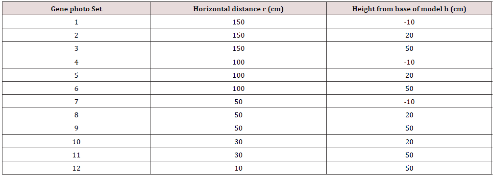
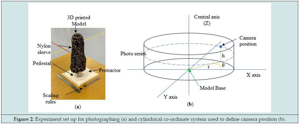
The 3D printed model (physical twin) was mounted onto a pedestal and covered in a patterned nylon sleeve as with the previous scan. A printed protractor was placed under the model to indicate 15° increments. A total of 288 photos were taken of the 3D model using the points designated by Table 1 at 15° increments (θ) based on a cylindrical co-ordinate system. A visual representation of the experiment set up and the location of photos is shown in Figure 2. The time to mesh the photos into a scan varied for the experiments, ranging from approximately 5-10 minutes to 2 hours depending on the workload queue for the Autodesk cloud computing system. Once scaned experiments were scaled using the longest visible length scale on a 30cm rule placed within the photographing volume, allowing for varying measurement points if sections of the rule were blurred or distorted. A secondary rule was also included to check the model sizing after scaling. The meshes were cropped to the base line of the model. This model was compared to the control model based on volume and surface area to evaluate to rank each scan.
Figure 2: Experiment set up for photographing (a) and cylindrical co-ordinate system used to define camera position (b).
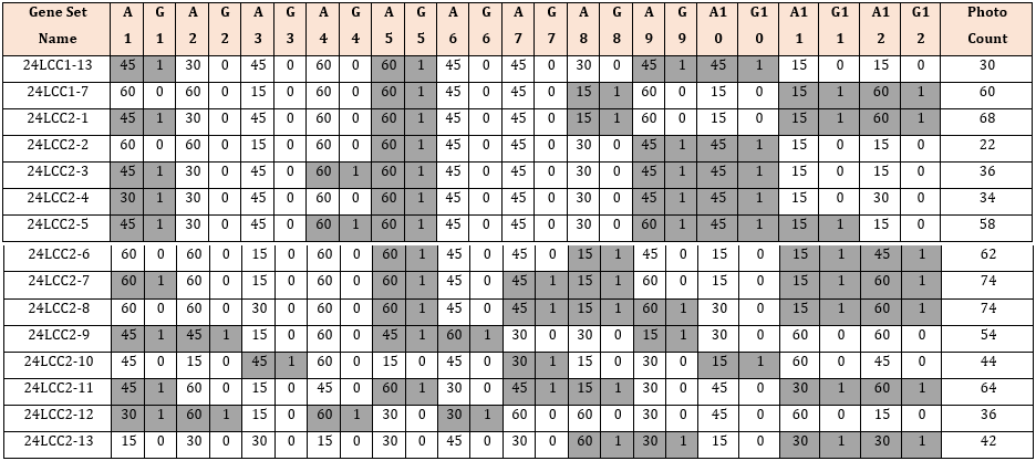
Simplified genetic algorithms were used to create a series of photo sets that were simulated with ReCap to generate mesh models from the selected photos. Twelve gene pairs were used, each consisting of two gene bits, controlling which photo sets would be included in the simulation (G columns) and what angle increment (A columns) would be used (Table 2). MS Excel (Microsoft, Washington, USA) was used to create, store, and compare genes. Initially, the genes were generated at random for the first generation, consisting of fifteen gene sets. Subsequent generations consisted of the top two fittest genes from the previous generation (24LCC1- 13,24LCC1-7); two genes generated from breeding the fittest two genes with a crossover point after the sixth gene pair (24LCC2-1 to 2); three mutated genes from each of the prior winners (24LCC2-3 to 8); and five additional randomly generated gene sets (24LCC2-9 to 13).
The gene crossover point for breeding was chosen as the midpoint between photos sets (6th gene pair): in Table 2 this is shown by the gene sets 24LCC2-1 and 2 when compared with their respective parents 24LCC1-13 and 7. For mutations (24LCC2-3 to 8) any gene bit from the parent gene set had a 10% chance of changing value: for columns G this mutation would change a 1 to 0 or vice versa, including or removing a photo series from the final gene set. By contrast, gene bits in the angle columns (A), if mutated, had an even chance of increasing or decreasing by one increment (15°, 30°, 45°, 60°), except 15° and 60° as the upper and lower increment which could only change to 30° and 45° respectively, as with gene pair 12 on 24LCC2-6 when compared to its parent LCC1- 7. Additionally, if mutations occurred only on the inactive gene pairs, then there would be no change to the overall experiment, and these mutations were re-generated. An example of this is shown in 24LCC2-8 where the A3 gene bit was 30° compared to the 15° of its parents (24LCC1-7), but this gene set was still included because it was still unique having further mutations on the 8th and 9th gene pairs.
The continual introduction of random gene sets for each generation helped to avoid early converging into a local optimum, ensuring an overall better inter-generational optimisation. When generated, each new gene set was compared to the existing gene sets to avoid duplicates. This was conducted only on active genes; this was done because gene sets could be different on the inactive genes making the experiments identical. A Visual Basic (VBA) code was written to automatically extract the relevant photos required by each gene set to be meshed using ReCap, simplifying the upload process. A fitness equation was then used which equally rewarded the generational ranking of averaged scan accuracy and the number of photos in the gene set. A total of seventy-four experiments were simulated across five generations using a similar method to that described previously. After the selection process, an additional photo reduction was carried out on the most fit gene set of the 5th generation. This was done by trialing the same set but with a single reduction by two angle increments for each active gene. The identified optimal gene set was then retested using an offset starting angle to test constancy of results..

A second model was generated from a sperate PoP mould, and a subsequent physical twin was 3D printed in green Thermal Polyurethane (TPU), referred to as Model 2. A research assistant with no experience of photogrammetry photographed both physical twins using the same method. They were provided with the list of photos required and the relative camera position, a tape measure for measuring distances, and instructed not to alter objects in the imaging environment.
Results
Of the seventy-four unique experiments conducted, fifteen scans were rejected due to incomplete or prominent extrusions from the model mesh. Across the experiments conducted, the average volume and surface area accuracy compared to the control model was 97.74% and 99.02% respectively, with an average photo count of fifty-two. The final selected gene set achieved an accuracy 98.09% (volume) and 99.56% (surface area) requiring twenty-six photos from three radial position sets. The cylindrical positions of the final gene set referred to as 24LCC6-3 were 100cm (r), 20cm (h), at 45o increments, 50cm (r), 50cm (h), at 60o increments and 30cm (r), 50cm (h) at 30o increments. To show the suitability of this scan the accuracy of 24LCC6-3 was compared to the accuracy of the same method from a varied start position relative to the model at 15 o, 30 o, and 60 o as shown in Table 3. To compare the repeatability of this method two models were scanned by both an experienced and inexperienced person. The comparison of the relative accuracy can be seen in Table 4.
Scan Model Analysis
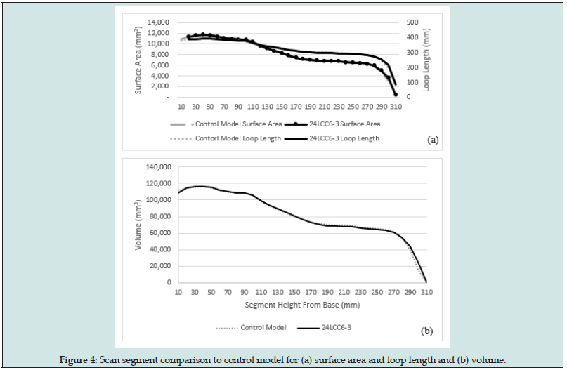
The mesh generated from 24LCC6-3 was imported to Fusion 360 and the scan and control model were aligned. Both models were then segmented based on parallel planes to the control model base in 10mm increments. The segment volumes, top surface areas and loop length are visualized in Figure 3, with the comparative metric plots in Figure 4. Across the central model region, between 20mm – 280mm the average percentage difference between scan and control model was 0.75% volume, 0.82% surface area, and 0.40% loop length. The percentage error was seen to increase for both the first and last segments due to slight discrepancies in model positioning and alignment in the 3D space as well as the angle that the scan mesh was sliced at. One of the metrics used in the literature for clinically acceptable socket fit deviations between socket copies is the Mean Radial Error (MRE). A fabricated socket with an MRE >0.25mm can be deemed clinically unacceptable [25]. When considering the calculated MRE based on loop length for the scan segments this method achieves an average difference of 0.20mm over the central 27cm region of the scan.
Figure 3: Visualisation of comparative metrics; scan model with alternate segments hidden and a single segment highlighted in blue (a); single segment with top surface highlighted (b); loop length of the same segment (c).
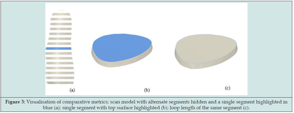
Figure 4: Scan segment comparison to control model for (a) surface area and loop length and (b) volume.
Discussion
The aim of this experiment was to identify an optimised method of photogrammetry for socket casts which could be easily incorporated into current practice. The genetic algorithms used were able to identify an image set consisting of only twenty-six photos from three radial position sets that achieved an accuracy for volume and surface area of 98.09% and 99.56% respectively, increasing to 99.13% and 99.65% during a repeat test. This is a significant reduction in photos when compared to the average across all experiments of 52.4. The most accurate experiment set tested achieved an accuracy of 99.59% and 99.81% for volume and surface area respectively, however it required sixty-two photos from four of the twelve possible radial positions. The fitness equation used in this experiment put equal weighting on the number of photos and the averaged accuracy for scan volume and surface area. The time required to take a full scan was impacted upon more greatly by the number of radial positions required compared to the number of angular increments required. A fitness equation with different weightings may have achieved a slightly more accurate scan without significantly impacting the photography time. The specific time taken for acquiring images was, however, out of the scope of this study.
The optimised method presented in this paper was intended to make inclusion into clinical practice as simple as possible. As such the use of smartphones, simple measuring and scaling devices, and printed nylon sleeve mean that the equipment cost and set up time was low. The equipment used was generic, but the use of specialised sleeves and tools would be of benefit to increase accuracy around the distal cavity and reduce the photography time. Cast preparation before photographs were captured would take approximately thirty seconds; preparation included sleeve application. The time to take photos of the part took approximately five minutes, which is comparable to other 3D scanning techniques [13]. However, the processing time was significantly longer. For this study, Autodesk ReCap Photo was used and the meshes were processed using cloud computing. Scans took up to two hours to mesh following the uploading of the photos, but this was heavily dependent on server workload, with the shortest scan taking 5-10 minutes. Other software could be used that processes images on a local machine, however this would limit it to one scan at a time, unlike with cloudbased systems.
Compared to the photogrammetry method for sockets explored previously, scanning the residuum model had a reasonably high reliability [18]. Out of the initial seventy-four experiment scans, ten were rejected due to significant surface anomalies or other model deformities. However, when the final selected experiment was rerun at varying start angles to check for reliability, all scans returned similar results. It should also be noted that taking additional photos to the recommended sets did not reduce the scan quality. When tested for inter-rater reliability by different users, the identified scanning method achieved accuracies of >99% in height and surface area, and >95% in volume by both an experienced and in experienced photographer. The most reduction in accuracy was 0.91% in volume for Model 1. This suggests that the method was not heavily reliant upon individual skill, providing appropriate basic verbal instructions are given.
The potential sources of error in this experiment can be divided into two categories: digital and physical. The digital errors were the scaling factor, mesh slice point and angle, and the digital alignment of models. The physical errors consisted of the thickness added by the nylon sleeve and the resolution of the 3D printed model. For this study, the physical errors were considered negligible. It should be noted that in some scans a ridge could be identified caused by the nylon sleeve stitching at the distal end of the residuum. Whilst this area was the in the distal cavity and may not affect clinical use, the ridge could be removed with the use of a nylon sock with a closed end. At the time of this study, authors could not find a closed sock suitable in either pattern or thickness. For the digital errors, the impact of the scaling factor was estimated at ±0.3%. The mesh slice angle and position to remove the surrounding area scanned was not directly measurable and would not impact the clinical effectiveness of the scan. Across the sixty-four experiments accepted, the average deviation in sliced model height was 1.9mm or 0.63%, however this deviation was a compound of slice angle and height and the scaling factor.
Conclusion
Seventy-four unique experiment sets were analysed to determine the optimal methodology for smartphone photogrammetry of a rectified residuum cast. The preparation time for the model using a patterned nylon sleeve was approximately thirty seconds with approximately five minutes to capture photographs, but software solving added a significant amount of time. The method employed in this study proved to be reliable and achieved a volume accuracy of 99.13 – 97.84%, which is within the clinically acceptable limit of 5% [26]. This photogrammetry method was conducted on a rectified residuum cast but is equally applicable to a positive direct patient cast. It also offers an overall higher accuracy of 2.26% volume difference versus 6.67% reported previously for internal socket scans. Overall, the proposed method is suitable for limb digitization in a clinical setting and comes at a relatively low cost compared to specialised alternatives.
References
- Dean D, Saunders CG (1985) A Software Package for Design and Manufacture of Prosthetic Sockets for Transtibial Amputees. IEEE Trans Biomed Eng 32(4): 257-262.
- Köhler P, Lindh L, Netz P (1989) Comparison of CAD-CAM and Hand Made Sockets for PTB Prostheses. Prosthet Orthot Int 13(1): 19-24.
- Goh JCH, Lee PVS, Toh SL, Ooi CK (2005) Development of an Integrated CAD-FEA Process for below-Knee Prosthetic Sockets. Clin Biomech 20 (6): 623-629.
- Johansson S, Öberg T (1998) Accuracy and Precision of Volumetric Determinations Using Two Commercial CAD Systems for Prosthetics: A Technical Note. J Rehabil Res Dev 35(1): 27-33.
- Öberg T, Lilja M, Johansson T, Karsznia A (1993) Clinical Evaluation of Trans-Tibial Prosthesis Sockets: A Comparison between CAD CAM and Conventionally Produced Sockets. Prosthet Orthot Int 17(3): 164-171.
- Afiqah Hamzah N, Razaz NAA, Sayuti Ab Karim M, Gholizadeh H (2021) A Review of History of CAD/CAM System Application in the Production of Transtibial Prosthetic Socket in Developing Countries (from 1980 to 2019). Proceedings of the Institution of Mechanical Engineers, Part H: J Eng Med 235(12): 1359-1374.
- Smith KE, Vannier MW, Commean PK (1995) Spiral CT Volumetry of Below-Knee Residua. IEEE Trans Rehabil Eng 3: 235-241.
- Safari MR, Rowe P, Buis A (2012) Accuracy Verification of Magnetic Resonance Imaging (MRI) Technology for Lower-Limb Prosthetic Research: Utilising Animal Soft Tissue Specimen and Common Socket Casting Materials. Scientific World Journal 2012: 156186.
- Nayak C, Singh A, Chaudhary H (2014) Customised Prosthetic Socket Fabrication Using 3D Scanning and Printing. Proceedings of 4th International Conference on Additive Manufacturing Technologies.
- Sengeh DM, Herr H (2013) A Variable-Impedance Prosthetic Socket for a Transtibial Amputee Designed from Magnetic Resonance Imaging Data. J Prosthet Orthot 25(3): 129-137.
- Pathak VK, Nayak C, Singh R, Dikshit MK, Sai T (2020) Optimizing Parameters in Surface Reconstruction of Transtibial Prosthetic Socket Using Central Composite Design Coupled with Fuzzy Logic-Based Model. Neural Computing and Applications 32(5): 15597-15619.
- Smith KE, Commean PK, Bhatia G, Vannier MW (1995) Validation of Spiral CT and Optical Surface Scanning for Lower Limb Stump Volumetry. Prosthet Orthot Int 19(2): 97-107.
- Armitage L, Kwah LK, Kark L (2019) Reliability and Validity of the ISense Optical Scanner for Measuring Volume of Transtibial Residual Limb Models. Prosthet Orthot Int 43(2): 213-220.
- Dickinson AS, Donovan-Hall MK, Kheng S, Bou K, Tech A, et al. (2022) Selecting Appropriate 3D Scanning Technologies for Prosthetic Socket Design and Transtibial Residual Limb Shape Characterization. JPO J Prosthet Orthot 34: 33-43.
- Solav D, Moerman KM, Jaeger AM, Herr HM (2019) A Framework for Measuring the Time-Varying Shape and Full-Field Deformation of Residual Limbs Using 3-D Digital Image Correlation. IEEE Transactions on Biomedical Engineering 66: 2740-2752.
- Barreto MA, Perez-Gonzalez J, Herr HM, Huegel JC (2022) ARACAM: A RGB-D Multi-View Photogrammetry System for Lower Limb 3D Reconstruction Applications. Sensors 22(7): 1-23.
- Hernandez A, Lemaire E (2017) A Smartphone Photogrammetry Method for Digitizing Prosthetic Socket Interiors. Prosthet Orthot Int 41(2): 210-214.
- Cullen S, Mackay R, Mohagheghi A, Du X (2021) The Use of Smartphone Photogrammetry to Digitise Transtibial Sockets: Optimisation of Method and Quantitative Evaluation of Suitability. Sensors 21(24): 8405.
- Whiteside S, Allen M, Barringer W, Beiswenger W, Brncick M, et al. (2022) Practice Analysis of Certified Practitioners in the Disciplines of Orthotics and Prosthetics. American Board for Certification in Orthotics, Prosthetics & Pedorthics, USA.
- Van der Stelt M, Grobusch MP, Koroma AR, Papenburg M, Kebbie I, et al. (2021) Pioneering Low-Cost 3D-Printed Transtibial Prosthetics to Serve a Rural Population in Sierra Leone – an Observational Cohort Study. EClinicalMedicine 35: 100874.
- Engsberg JR, Clynch GS, Lee AG, Allan JS, Harder JA (1992) A CAD CAM Method for Custom Below-Knee Sockets. Prosthet Orthot Int 16(3): 183-188.
- Sanders JE, Rogers EL, Sorenson EA, Lee GS, Abrahamson DC (2007) CAD/CAM Transtibial Prosthetic Sockets from Central Fabrication Facilities: How Accurate Are They? J Rehabil Res Dev 44(3): 395-405.
- Goh JCH, Lee PVS, Ng P (2002) Structural Integrity of Polypropylene Prosthetic Sockets Manufactured Using the Polymer Deposition Technique. Proc Inst Mech Eng H 216(6): 359-368.
- Hsu C-H, Ou C-H, Hong W-L, Gao Y-H (2018) Comfort Level Discussion for Prosthetic Sockets with Different Fabricating Processing Conditions. BioMedical Engineering OnLine 17: 145.
- Sanders JE, Severance MR, Allyn KJ (2012) Computer-Socket Manufacturing Error: How Much before It Is Clinically Apparent? J Rehabil Res Dev 49(4): 567-582.
- Sanders JE, Fatone S (2011) Residual Limb Volume Change: Systematic Review of Measurement and Management. J Rehabil Res Dev 48(8): 949-986.

Top Editors
-

Mark E Smith
Bio chemistry
University of Texas Medical Branch, USA -

Lawrence A Presley
Department of Criminal Justice
Liberty University, USA -

Thomas W Miller
Department of Psychiatry
University of Kentucky, USA -

Gjumrakch Aliev
Department of Medicine
Gally International Biomedical Research & Consulting LLC, USA -

Christopher Bryant
Department of Urbanisation and Agricultural
Montreal university, USA -

Robert William Frare
Oral & Maxillofacial Pathology
New York University, USA -

Rudolph Modesto Navari
Gastroenterology and Hepatology
University of Alabama, UK -

Andrew Hague
Department of Medicine
Universities of Bradford, UK -

George Gregory Buttigieg
Maltese College of Obstetrics and Gynaecology, Europe -

Chen-Hsiung Yeh
Oncology
Circulogene Theranostics, England -
.png)
Emilio Bucio-Carrillo
Radiation Chemistry
National University of Mexico, USA -
.jpg)
Casey J Grenier
Analytical Chemistry
Wentworth Institute of Technology, USA -
Hany Atalah
Minimally Invasive Surgery
Mercer University school of Medicine, USA -

Abu-Hussein Muhamad
Pediatric Dentistry
University of Athens , Greece

The annual scholar awards from Lupine Publishers honor a selected number Read More...


