Lupine Publishers Group
Lupine Publishers
Menu
ISSN: 2637-4668
Research Article(ISSN: 2637-4668) 
Nonlinear Analysis of Space Structures under Dynamic Loads Volume 2 - Issue 3
Qasim M Shakir*
- University of Kufa, Iraq
Received: May 18, 2018; Published: June 11, 2018
Corresponding author: Qasim M Shakir, University of Kufa, Iraq
DOI: 10.32474/TCEIA.2018.02.000140
Abstract
A theoretical analysis is presented for estimating the in-space large displacement elastic stability behavior of structures subjected to either proportional or non-proportional dynamic loads. The analysis adopts the beam-column approach, which models the structure’s members as beam-column elements. The formulation of the beam-column element is based on the Eulerian approach allowing for the influence of the axial force on the bending and the torsion stiffness. Also, change in member chord length due to the axial deformation and flexural bowing are taken into account. Newmark- β method is used as a time integration technique to plot the time-deformation curves. Damping effect is expressed using Raleigh damping matrix. Several examples have been solved to insure the accuracy of the present analysis.
Introduction
A dynamic load may cause instability of a structure, even if the structure remains stable under a static load of the same magnitude as the dynamic load .Such phenomenon may occur within the elastic range. So, the maximum deformation response abruptly increases at some point with respect to the magnitude of loading. When this kind of instability problem to be solved ,geometrical non-linearity must be considered in the dynamic analysis as that in static instability analysis. To days, studies conducted on dynamic analysis of frames with geometric non-linearity are mainly concerned with plane frames. Such studies dealing with three dimensional frames are seldom found in the literature. The objective of this paper is to extend the large deformation static analysis of space structures presented previously by Oran [1] and then by kassimali and abbsania [2] to deal with the time dependent loading. Members are assumed to be prismatic connected by frictionless hinges for trusses and rigid joints for frames.
Basic Member Force Deformation Relations
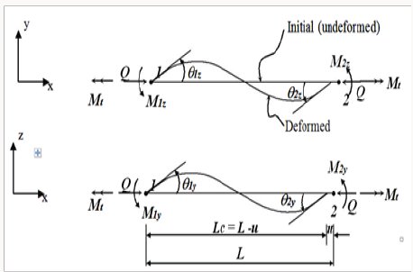
The basic member force-deformation relations consistent with the conventional beam column theory [1] Figure 1 are:
Both stability and bowing are dependent on the axial force parameter (qn) and their explicit transcendental and series expressions are given by Oran [3,1] and kassimali and abbsania [2].
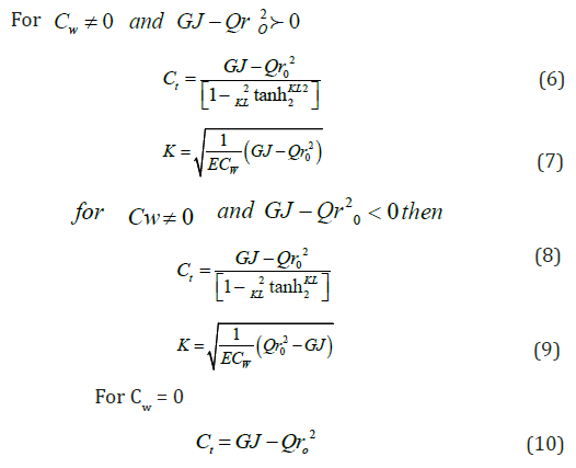
The torsional factor (Ct) in equation [4] considers the influence of axial force on member torsional stiffness [1]
Member End Effects
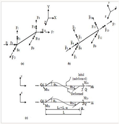
Consider an arbitrary prismatic member of a space frame, and let {F} and {F’} denote member end forces in the global and local coordinates respectively (Figures 2a & 2b), the relationship between {F} and {F’} can be written as:
{F}=[R]{¯F} (11)
Figure 2:
Member end effects,
A. Member forces in global coordinates,
B. Member forces in local intermediate coordinates,
C. Relative member deformations and corresponding forces.
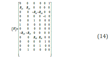
[R]: is the (12x12) orthogonal matrix [5] and defined as:
[r]: is the (3x3) member orientation matrix, refers to the deformed configuration of the member. This matrix refers to the deformed configuration and must be updated according to the N-R type technique [6]. Similarly the member forces {F}are related to the forces {S} associated with the relative member deformations (Figures 2b & 2c) by:
{F}=[B]{S} (13)
[B]: is the instantaneous static matrix defined as:
In which
Member orientation matrix
Initial member orientation matrix [r0]
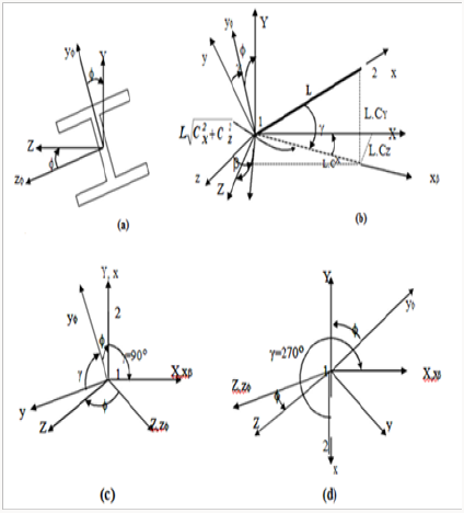
It must be used for the first increment and for the first iteration only. This matrix can be derived by taking in consideration that the transformation from the local to the global coordinates to take place by rotating the member through the angles (β, and ) about the Z-, Y- and X-axis, (Figures 3a & 3b).The final form of this matrix is [5]:
Figure 3:
Transformation of coordinate system.
A. Rotation of a space frame moment about x-axis.
B. Rotation of axes for arbitrary space frame member.
C and D Rotation of axis for vertical space frame.
When the member is vertical, the initial member orientation matrix [r0] will be :
CY = 1 for γ=900 and CY =-1 for γ=2700
Current Member Orientation Matrix
Three alternate methods are available in the literature that are used to determine the current member orientation matrix for the deformed configuration. Two of these are presented by Oran [1] and the third one was presented by Kassimali and Abbasania [2]. One of the procedures of Oran was utilized in the present analysis. This method is based on the variation of the principal directions from one section to another, then the incremental joint orientation matrix is calculated in each increment, and the total joint orientation matrix is updated for the next increment. The current member orientation matrix, then, is obtained by averaging the orientation of the two end sections of the member [1]. Thus, the current member orientation matrix can be expressed as:
[r]=1/2{[D(1)]+[D(2)]} (18)
Where [D(1)],[D(2)]: are the current section orientation matrices of the two ends of the member.
Member Tangent Stiffness Matrix
The incremental relationship between the end forces and the end displacements {ΔV} in the global coordinates can be written as:
{ΔF} = [T ]{ΔV} (19)
And [T] is the member tangent stiffness matrix in global coordinates which can be written [6][11] as:
[T]=[R][B][t][B]+TΣ K=I6SK[g-(-k)][RT] (20)
Where [T] is the member tangent stiffness matrix inb eulerian
coordinates and it is gien axlicity with [g(k)] in Appendix I. The dynamic equation of motion [7,8] for nonlinear systems
can be written as [M]{X¢¢}+[C]{X¢}+[T]{X} = [F ( t )] (21) The consistent mass method has been adopted in the present
study. In this method, mass coefficients corresponding to the nodal
coordinates can be evaluated depending on the principle of virtual
work. Accordingly, the mass coefficients can be given in a general
form as: Damping matrix has been represented using the so-called
Raylieh type of damping which may be expressed as: [C] =α1 [M] + α2[T] (23) The nonlinear dynamic response of structures is investigated in
this work using the step -by -step numerical integration procedure
with a Newton type of iteration performed within each time step
to satisfy the equation of motion .The Newmark -β method with
β=1/4 and γ=1/2 is used Assuming that the displacement, velocity and acceleration
vectors are known at time to=0 Then, the general procedure of analysis is as follows [9,10] a) Calculate the following constants b) form the matrices [T],[M] and [c] for each member ,then,
form the overall matrices by the assemblage of the element
stiffness matrices c) From the effective stiffness matrix, initially assuming
linear behaviour [Teff]=a1[M]+a2[C]+[T] (24) [C] =b1 [M]+b1[T] (25) d) From the effective load vector e) Solve for the increment displacements (for time t + Δt ) f) iterate for dynamic equilibrium a. i=i+1 b. evaluate the ( i-1 )th approximation of acceleration,
velocity and displacement vectors c. evaluate the (i-1)th unbalanced joint forces d. compute the correction of the displacement increment
{ΔX} e. evaluate the corrected displacement vector f. check for convergence g. if “No” ,go to 6.a else return to step 3 to proceed to the next
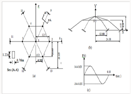
time step The response due to a harmonically varying vertical load
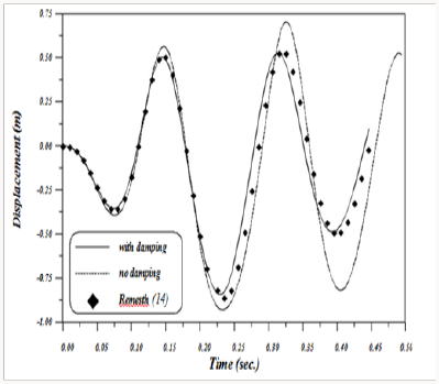
at the crown of the dome shown in Figure 4 has been studied by
Remesth [11] using the finite element approach with two elements
per member . Newmark-method with ( β=1/4 and γ=1/2 ) has
been used. The peak value of the concentrated load is chosen to be
(34.4MN) with time step size of (0.0025sec) and natural frequency
of the applied load is taken to be (0.15sec).Damping is included
in the analysis and it is determined from a model damping ratio
(5%) for the mode with the longest natural period initially equal
to (0.175sec). This example is analyzed in the present work with
and without damping using Newmark method with the same load
properties, each member is modeled with one element and the
vertical response of the loaded joint for both studies is illustrated
in Figure 5. It is clear that a good agreement may be obtained using
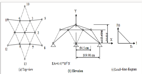
the present analysis including damping effects. The geodesic dome shown in Figure 6 is to be analyzed under
triangular dynamic load applied at the central point [6] Kassimali
and Bedhendi [12] analyzed this structure using a stiffness method
based on an Eulerian formulation accounting for arbitrarily large
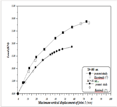
displacements. Two time durations (Td=0.005sec, Td=0.01 sec)
were used. It was found that for short impulse duration, the critical
load decreases steadily as duration increases and it approaches
that of the static load case for long time durations. The problem
is solved in this study under the same loading conditions and the
results are shown in Figure 7 which indicates the efficiency of the
computer program developed in the present study to predict the
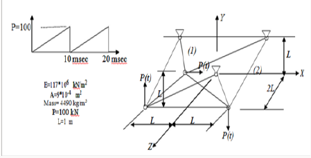
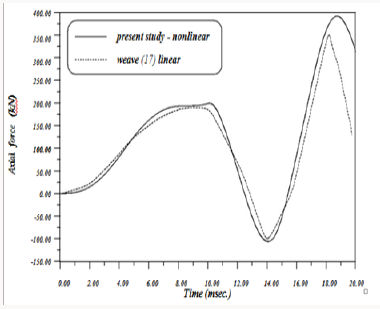
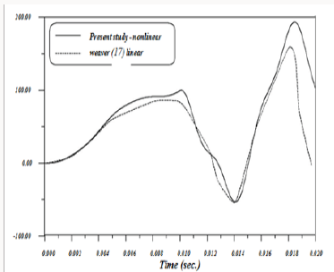
large displacement behaviour of space frames under dynamic loads. The space truss shown in Figure 8 has been analyzed by Weaver
[5] using linear analysis .The same structure is considered here
to show the importance of studying large deformations for such
structures under dynamic loads. The variation of axial force with
time for members [6,13] for both studies are shown in Figure
9 & 10. It is obvious that at time(t=19 msec),the linear analysis
underestimates the axial forces for the two members by (15%) and
(30%) respectively [14-17]. The present work shows the importance of considering the large
deformations behaviour in the analysis of space structure under
dynamic loading within elastic range. The beam column which have
been utilized previously for the analysis of plane structures under
static and dynamic loads and also for space structures under static
loading is extended in this work to deal with the analysis of space
structures under dynamic loading. Although of its simplicity, Rayleigh model may be adopted to
represent the damping effects. Also it is found that the method
of updating the member orientation matrix by averaging the end
section orientation matrices is adequate enough to be adopted
in the analysis of space structures subjected to time dependent
loading (Appendixs 2 & 3).Dynamic Analysis
The Computational Technique
Applications
Framed Dome under Harmonic Loading
Geodesic Dome under Triangular Load
Space Truss with Nine Prismatic Elements
Conclusion
References

Top Editors
-

Mark E Smith
Bio chemistry
University of Texas Medical Branch, USA -

Lawrence A Presley
Department of Criminal Justice
Liberty University, USA -

Thomas W Miller
Department of Psychiatry
University of Kentucky, USA -

Gjumrakch Aliev
Department of Medicine
Gally International Biomedical Research & Consulting LLC, USA -

Christopher Bryant
Department of Urbanisation and Agricultural
Montreal university, USA -

Robert William Frare
Oral & Maxillofacial Pathology
New York University, USA -

Rudolph Modesto Navari
Gastroenterology and Hepatology
University of Alabama, UK -

Andrew Hague
Department of Medicine
Universities of Bradford, UK -

George Gregory Buttigieg
Maltese College of Obstetrics and Gynaecology, Europe -

Chen-Hsiung Yeh
Oncology
Circulogene Theranostics, England -
.png)
Emilio Bucio-Carrillo
Radiation Chemistry
National University of Mexico, USA -
.jpg)
Casey J Grenier
Analytical Chemistry
Wentworth Institute of Technology, USA -
Hany Atalah
Minimally Invasive Surgery
Mercer University school of Medicine, USA -

Abu-Hussein Muhamad
Pediatric Dentistry
University of Athens , Greece

The annual scholar awards from Lupine Publishers honor a selected number Read More...


