


Lupine Publishers Group
Lupine Publishers
ISSN: 2637-4668
Research article(ISSN: 2637-4668) 
Long-Term effects of Environment on Seismic Performance of Dez Concrete Arch Dam Volume 4 - Issue 1
Received: August 13, 2020; Published: September 04, 2020
Corresponding author: Mojtaba Labibzadeh, Associate Professor of Structural Engineering, Faculty of Civil Engineering and Architecture, Shahid Chamran University of Ahvaz, Iran
DOI: 10.32474/TCEIA.2020.04.000176
Abstract
In the first part of this paper, the degradation of the mechanical properties of the mass concrete of the Dez concrete arch dam under the long-term effects of its environment as well as its loading history has been investigated using an innovate inverse analysis method. For performing that inverse analysis, an objective function was defined and then it was attempted to minimize that. That function was defined as the sum of the squared differences between the displacements obtained from a developed enhanced FE model in the ABAQUS standard software by the authors in the current study for each assumed set of the degraded mechanical properties of the dam as input variables and those obtained from the inverse pendulum’s records of the dam. For the sake of the generality of the problem, in performing such FE analyses, it was assumed that the behavior of the concrete material of the Dez dam has transformed gradually from initial homogeneous and isotropic undamaged behavior to the heterogeneous and orthotropic deteriorated behavior under the long-term effects of the environment as well as load agencies. Hence, the vertical sections of the dam were divided into nine and six subsections along the thickness and height directions of the dam, respectively. In each subsection, a transversely isotropic degraded elastic constitutive law was considered for characterizing the concrete long-term deterioration phenomenon. Obtained results revealed that the long-term deterioration of the mass concrete of the Dez dam is in fact a heterogeneous and anisotropic process because that the magnitude of the above mentioned defined objective function was obtained smaller than the corresponding value in the previous study of the authors which was performed based on the homogeneous and isotropic damage evolution assumptions. Core test results from the mass concrete of the dam reported by a consulting engineer company confirmed the concrete degradation predicted by the proposed model. After that, the behavior of this dam against an earthquake excitation was investigated considering the above-mentioned degradation of its mechanical properties and the obtained results were compared with its corresponding behavior considering its initial un-damaged mechanical properties for the mass concrete. Comparisons revealed considerable growth in the enveloped tensile stresses which can change the initial assumed safety margin design factors of the dam and necessitates the re-evaluating of the dam stability.
Keywords: Concrete; Thermal inverse analysis; Heterogeneous; Transversely isotropic; Long-term damage; Arch dam; Seismic response
Introduction
Much of the hydraulic structures like arch concrete dams are rapidly approaching, or in some cases have already passed their original design life. It is not surprising to say that these old concrete structures which some of their surfaces are submerged in the water for a long time, experience more degradation in their mechanical features than those structures which remain in dry environmental conditions along their operational life Dam Safety Technology Development Program 2005 [1]. This phenomenon may probably be the result of, to some extent, the effects of saturation of micro voids in the concrete mass Wittmann [2]; Pihlajavaara [3,4]) or/ and to some extent of the chemical dissolution reactions that occur in the wet concrete parts Kuhl et al. [5]; Nguyen et al. [6]. Besides the effect of water, some unexpected external loads, like severe earthquake loads, can cause the degradation of strength and integrity of old concrete arch dams.
Consequently, it can be outlined that the weakening of aged concrete arch dams may have resulted from two main factors:
1. Time variant external loading, and
2. Environmentally induced loading. The first load category
may consist of a sudden reduction of the reservoir water level,
earthquake excitations, mountain slippage, and abnormal
temperature changes Chen and Ren [7]; Camara and Oliveira
[8]; Ghanaat [9].The second main source includes moisture and
heat transferASTM 1985 [10]; Cerny and Rovnanikova 2002
[11], freeze-thaw action, dissolution processes such as calcium
leaching Ekström[12], and chemical expansive reactions such
as sulfate attack or alkalisilica reaction Ardito et al. [13];
Moshtagh and Ghaemian [14]; Wang et al. [15].
Three different approaches have been persuaded until today to address and contribute the effects of these two different origin types of loading in the analysis of aged concrete arch dams:
1. The first method studies the changes in the characteristics
of transmitted and received waves which travel through the
thickness of the arch dam. This nondestructive test method is
used for estimating the strength and elastic properties of mass
concrete and for locating and characterizing voids and cracks
within the structure Bond et al. [16,17].
2. Development of mathematical models which quantify and
measure the aging effects in structural analysis is the second
method [5,6,9,15,18,20].
3. In the third group, named as diagnosis approaches,
the damage diagnosis methods have been implemented for
identification of degraded strength parameters such as elastic
modulus of the dam Wittmann [2]; Maier et al. [21]; Fedele et al.
[22]; Garbowski et al. [23].
The diagnosis approaches include five different strategies:
1. Assessment of long-term monitoring observations and
comparison with past behavior of the same dam and/or similar
dams Alvin et al. 2003 [24],
2. Local identification of concrete constitutive parameters
on the surfaces by flat jacksFedele and Maier 2007 [25].
3. Local identification of concrete constitutive parameters
in depth by overcoring or dilatometric techniques Fedele et al.
2005 [26].
4. Dynamic vibration by vibrodynes and measurements
through accelerometers and identification of young modulus
distributions based on modal analysis in linear dynamics
Salawu 1997 [27], and
5. Hydrostatic loading attributable to fast reduction in water
surface in the reservoir, measurement of deformations by
instruments of the dam such as pendulums, collimators and/
or interferometric radar and statical overall inverse analysis
of elastic moduli through a linear finite element model (FEM)
or nonlinear FEM if vertical block relative movements are
considered Ardito et al. [28]; Ardito and Cocchetti [29]; Fedele
et al. [22].
Aggressive environment can contribute into the diminishing of the concrete mechanical properties directly or indirectly. Concrete is being deteriorated with time under the effects of ambient temperature and moisture fluctuations. A rise in temperature or moisture content of concrete can cause expansion; inversely, a drop in temperature or drying is generally associated with contraction or shrinkage in concrete, on the other hand. Under these repeatable circumstances, if concrete deformations are prevented or restrained, stresses build-up within this worldwide construction material. Consequently, these environmental-induced cyclic stresses can lead to the deterioration of concrete.
The Dez concrete arch dam is located in an aggressive condition from the environmental point of view based on the study of Naik (1985) [30]. According to this study, the worst environmental condition of concrete is occurred when the weather is hot and contains high humidity. He described this situation quantitatively and specifically mentioned that at an air temperature of 122 °F and relative humidity of 100%, concrete becomes weak both in compression and tension. He added more that this is a critical condition for which the maximum load for a concrete structural member should be re-computed. Holding this issue in mind, it is interesting to note that the ambient temperature in the site location of the Dez dam reaches to 50 °C (122 °F) in the summer. Remembering this circumstance, on the other hand, the upstream face of the Dez dam at the same time is exposed dominantly to the reservoir water and therefore it is rational to suppose that some portions of the upstream face of the dam are completely saturated. So, it is no surprise if the environmental condition of the Dez dam in some days of the summer is classified as an aggressive condition.
Downie [31] performed a comprehensive study on the effects of heat and moisture transport within the concrete on its mechanical properties. He concluded that higher temperature and degrees of saturation will yield lower concrete strength in compression, tension and corresponding modulus of elasticity. He added more that these two factors have negligible effect on Poisson’s ratio. Additionally, De Borst and Peeters [32] found that the high temperature has a considerable effect on concrete creep strains. They declared that rising of temperature accelerates the creep of concrete considerably. Furthermore, the mechanism of force bearing in an arch dam is to transfer the hydrostatic pressure of the reservoir horizontally to the abutments and vertically to the foundation. At the Dez arch dam, because of the narrow shape of the canyon (V shape), the forces mainly are transferred in the horizontal direction with arch actions so the concrete of the Dez dam even near to the crest is under strong sustained compressive pressure U.S. army corps of engineers [33]-Engineering and Research Center [34]. This pressure near to the foundation is triaxial and near to the crest is biaxial because of the different thicknesses of these portions. So, the creep of the Dez concrete is inevitable and as a consequence the degradation of integrity and stiffness of the dam due to this creep is steadily becoming more progressive Ruiz MF et. al. [35].
Besides to the above-mentioned direct physical environmental effects, the indirect chemical effects of the environment caused the concrete of the Dez dam to degrade progressively with time. High potential source of chemical degradation of the Dez dam is the calcium leaching. According to what reported by Dodds [36], the Dez river water is completely saturated with CaCO3. So, based on findings of Cerny and Rovnanikova [11] reported in their book, Transport Processes in Concrete, in the upstream face of the Dez dam, high hydrostatic pressures cause the water to diffuse into the inner parts of the concrete layers and dissolves the dissoluble hydration products, specifically in this case, i.e. the Ca(OH)2 of the cement paste. That dissolution is strongly possible because some amounts of the free carbon dioxide CO2.nH2O in the reservoir water of the Dez dam react with CaCO3 existed in that water to form carbonic acid H2CO3. This acid water diffuses into the concrete and dissolves the hydrated products and transports them to the reservoir water. This process leads to an increase in porosity of the concrete and consequently to decrease of the integrity and strength of the concrete Ekstrom [12]. Foregoing mentioned environmental factors along with the unexpected external mechanical loadings such as abutment movements or a sudden reduction in the reservoir water level or occasionally moderate earthquakes (all of them have occurred during the Dez dam life) are strengthening this hypothesis that the initial mechanical properties of the young dam can be deteriorated during a long period of time (dam is 42 years old). Deterioration of concrete is both a physical and chemical phenomenon of the cement paste, the aggregate and the paste-aggregate interface. If degradation of concrete is progressing over time, the concrete structure may not be able to withstand the designed loads even if they have not changed (Report DSO-05-05-2005) Even if there is no aggressive chemical in contact with the concrete of the dam, Nguyen et. al. [6] as it was mentioned, the saturation-dependent internal stresses acting on the nano- and microscales develop as a consequence of molecular adsorption and capillary condensation. Bangert et. al. [37] Moisture movement in porous media of concrete of the dam may initiate cracks, and in turn, cracks strongly affect the permeability of the concrete Grasberger and Meschke [38]. In the present study, as a promotion to the previous attempt of the authors and his co-workers Labibzadeh et. al. [39], the degradation of mass concrete of the Dez dam was evaluated in more detail using a more sophisticated numerical degradation model. In that preceding work, it was demonstrated that the concrete of the Dez dam has been deteriorated and its mechanical properties have been changed after a long time (approximately 45 years) from which the dam is under service. Furthermore, in that attempt, the degraded mechanical properties of the dam were identified using a novel thermo-elastic inverse numerical model developed in that previous research Labibzadeh et. al. [39]. It should be noted that in that research, it was postulated that this degradation has a homogeneous and isotropic nature. Although the obtained results of some core tests conducted recently on this old dam by a consulting engineering group verified the predicted results obtained from the mentioned above numerical model and confirmed that degradation in general undoubtedly, they could not guarantee the homogeneity and isotropy of this deterioration with the same degree of certainty. Hence, in the first part of this research, the degradation of dam’s concrete was considered as a heterogeneous and anisotropic process and it was decided to investigate the validity of this hypothesis using that numerical model which was developed in previous study Labibzadeh et. al. [39]. For the sake of brevity, the description of that analytical model (thermo-elastic inverse model) has not discussed again here. But it should be noted that, in that model, an error or residual function has been defined which plays the principal role in that mentioned above validity process. In other words, it is postulated in this study that if the computed value of the error function from the new proposed sophisticated model which will be described in the next section is obtained smaller than the corresponding value in the previous work, it can be concluded that the new numerical model has a more realistic feature and is more reliable. This assumption, in fact, is a foundation that this new research is going to be built on that. So, the degree of the reliability of the obtained results depends on the degree of the soundness of that assumption. The above mentioned error function in this study similar to the previous work, in fact, indicates the difference between the computed displacement vector of the nodal points of the dam obtained from the new presented enhanced thermo-elastic inverse model and those obtained from the inverse pendulums of the dam. Hence, the smaller the error values the more degree of the reliability of the implemented analytical model. It should be noted that the difference between the new model and the old model used in preceding study is that in the present model, the material constitutive behavior of concrete of the Dez dam is considered to be transversely isotropic in contrast to the old version which was considered as isotropic and also the degradation of the dam is defined to be heterogeneous in opposite to the forgone work which was postulated as a homogeneous phenomenon. At the end of the part one of the paper, the obtained results will confirm that the degradation of the concrete mechanical properties of the Dez dam has a heterogeneous and anisotropic feature. Second part of this study deals with the seismic assessment of this dam considering obtained degraded elastic strength against to the Tabas ground motion.
Part I: Transversely isotropic elastic degradation
As it was mentioned in the previous research, the behavior of the dam and its abutments are still elastic based on the observations from the instruments located in the dam and supports besides to the available geological and geotechnical report of the dam at construction time Labibzadeh et. al. [39]. From the heterogeneity point of view, it must be said that the environmental conditions at the upstream and downstream faces of the Dez dam are completely different. The upstream face of the dam is in permanent contact with the reservoir water which is completely saturated whereas the downstream of the dam is exposed to the ambient weather which is nearly dry. The wetness in Dez dam accelerates the degradation whereas dryness slows it down. The temperatures in these regions are also different. Temperature values at upstream are moderate and at downstream are excessive. Excessive temperatures accentuate the deterioration and moderate temperatures play it down for concrete. So, the moisture content and temperature change significantly through the thickness of the dam at each altitude level. In addition, the variation of these two environmental parameters with respect to time is not the same for the upstream and downstream faces. Therefore, it is rational to expect that the concrete deterioration of the Dez dam cannot be a homogeneous process along the dam thickness. Furthermore, the moisture and temperature are also changing along the height direction of the dam. Hydrostatic pressure varies linearly from the top to the bottom of the dam with high magnitudes at the bottom. So, the moisture can penetrate and affect lower parts of the dam more effectively than the upper portions. On the other hand, because of the different sunshine expositions, the temperature would change along the height of the dam both in upstream and downstream faces. Hence, the concrete deterioration cannot be a homogeneous process along the dam height look likes the discussed thickness direction.
On the orientation of the anisotropy, it should be noted here that the biaxial stress resultant at the in-planes of the Dez dam (parallel planes to the dam upstream/downstream surfaces) remains approximately constant due to the main actions imposed on the dam: hydrostatic pressures and gravity loads. The existence of higher compressive stresses in arches than those verified in cantilevers at the dam upper portions and at the same time the actions of higher compressive stresses in cantilevers than those developed in arches at lower altitudes of the dam may interpret well the above mentioned hypothesis. Apart from these natural boundary conditions, the essential boundary conditions of the Dez dam also strengthen the idea of the transversely isotropic nature of the elastic degradation tensor of the Dez concrete dam. The elongations of the dam in arch and cantilever directions are nearly the same but are much greater than the dam elongation in the thickness direction. So, it is rational to expect that the degradation mechanism has different effects on the in-planes and out-of-planes (planes regarded as being perpendicular to in-planes) of the dam see Figure 1.
Figure 1:Transversely isotropic elastic degraded nature of Dez concrete.

It should be emphasized here that; the authors of this paper like to Fedele et. al [22], believes that the degradation of concrete due to the environmental effects only could be merely considered as an isotropic damage process in average behavior of the dam. However, due to past extreme loadings from Fedele and his collaborators’ point of view and from the opinion of the authors of this article due to permanent main ordinary loadings as well as past extreme loadings, this damage process can be transformed into an anisotropic process. Past extreme loadings such as earthquakes or unusual reservoir water reductions can produce diffused cracks within the concrete and on the other hand, the permanent main actions e.g. hydrostatic and gravity loads can provide a dominant state of stresses in the concrete, each of them makes the evolution of the long-term deterioration of the dam to take anisotropic features.
After extensive examination of the literatures, the authors concluded that Oliveira et. al. 2010 [40] and Garbowski et. al, 2011 [23] are probably the only two diagnostic studies conducted on concrete dams considered the degradation of concrete as an anisotropic process. Oliveira and his collaborators performed a modal analysis on the Cabril arch dam located in Portugal using an inverse analysis method for dam material parameter identification. However, they have only modeled a small damaged zone (cracked zone) of the dam with an orthotropic transversely isotropic elastic constitutive law and considered the rest of the dam as isotropic material. Moreover, they have assumed that two of the fifth independent elastic modulus e.g. the elastic modulus and Poisson’s ratio of the plane of isotropy are known values and only three remained unknown material parameters were identified in their research. On the other hand, Garbowski et al. [23] performed an inverse analysis on a roller compacted concrete dam using the so called DIC technique (Digital Image Correlation) for analyzing the obtained images from a portion of the surface of the dam which experienced some displacements under the pressure imposed on it with a flat-jack through a T-shaped slots. They have identified the elastic and shear modulus of the concrete in the presence of orthotropy. They reported that the advantage of their method was that no data from extensometers were needed. Although Garbowski and his colleagues have performed a worthwhile attempt for diagnosing the material parameters of the dam, but the authors of this paper believe that their approach may suffer from two main drawbacks. Firstly, the accuracy of obtaining results is strongly dependent on the accuracy of the field operations and related mathematical theories. Secondly, the results are obtained from a local portion and under an artificial procedure (virtual loadings and virtual resulted displacements), so they cannot be extended easily to the global mass concrete of the dam. Apart from these two mentioned deficiencies, they have considered the dam as a homogeneous medium and taken the Poisson’s ratio components of transversely isotropic elastic tensors as known parameters. So, they have only identified three remained other parameters like the work of Oliveira et al. [40].
This issue motivated the authors of this article to investigate in more detail the long-term aggression of concrete of the Dez dam in the presence of anisotropy using the innovative thermal inverse analysis labibzadeh et. al. 2014 [39].
Considering Figure 1, the constitutive law for the long-term deterioration of Dez concrete can be stated as a relation (1):
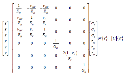
In the above relation, denotes the Young’s modulus along the x-axis (axis of elastic symmetry) and indicates the corresponding elastic parameter in the plane of isotropy e.g. Y-Z plane herein. is Poisson’s ratio, characterizing the transverse strain reduction in plane of isotropy (Y-Z) due to tensile stress in a direction normal to it (X). represents also Poissin’s ratio but in the plane of isotropy. stands for the shear modulus for planes normal to plane of isotropy.
Methodology
According to equation (1), in this study, five independent constants of the compliance matrix; C; were considered in a general form to be the unknowns and extensive trials have been made to identify them through a thermal inverse analysis algorithm described in detail in labibzadeh, et al. [39]. The dam was subdivided into nine individually homogeneous zones in the thickness direction and into six similar sections along the height of the dam. To each of these sub-regions, the above mentioned five unknowns consist of two Young’s modulus, two Poisson’s ratios and one shear modulus were attributed as representative of the long-term concrete damage to be estimated. This subdivision was performed taking into account the Dez dam geometrical characterizations and construction practice stages as well as optimization of the time consumes for each analysis to be completed. Figure 2 shows a part of the dam with the scheme used for sub-dividing. The Word ‘Block’ in this figure marks the vertical cantilevers of the dam separated with the contraction joints. These contraction joints were contributed in the F.E. thermal inverse analyses.
Figure 2: Dez dam sub-divisions.

The unknowns mentioned before were determined through performing F.E. thermal inverse analyses and subsequent to each of these analyses performing parameter identification. To this end, for each assumed set of five unknown parameters, a Finite Element (F.E.) analysis has been performed taking into account the thermal loads induced in the dam due to ambient temperature gradients as well as hydrostatic and gravity loads. The details of F.E. model was completely described in the previous accompanied paper Labibzadeh et al. [39]. A schematic F.E. model of the dam has been depicted in Figure 3 & 4 and the true F.E. model has been shown in Figure 5.
Figure 3:Dez dam sub-divided from downstream view.

Figure 4: Dez dam schematic F.E. model.

Figure 5: F.E. Model of the Dez dam and its support.

For dam and its geologic support modeling; 27241 and 4327 elements; correspondingly 2503 and 3471 nodal points were used respectively, leading to considering of 17992 degrees of freedom for the problem in hand. The temperature gradient for each nodal point in F.E. model was obtained using the records of the thermometers located within the dam body. Based on these data records, the gradient was defined as the difference between the recorded temperatures of a node in two different days of a specific year; in this study 2007s; see Figure 6. These days were selected in such a way that provides a relatively noticeable temperature difference in the nodes with no significant difference in the reservoir water level of the dam.
Figure 6: Recorded water level, upstream and downstream temperatures-2007s.

By performing each F.E. analysis, relative displacements of the nodal points of the dam were computed and recorded in a vector named as (computed displacement vector). This vector is a function of those mentioned unknown parameters; based on the theory of elasticity rewritten in F.E. framework briefly here (Eqs. 2 to 4) where in turn includes two Young’s modulus, two Poisson’s ratios and one shear modulus, according to Eq. (1).
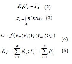
In relations 2 to 4, is the stiffness matrix; denotes the corresponding nodal force vector contains the effects of gravity, hydrostatic and thermal actions; is the strain-displacement matrix; indicates the transversely isotropic elastic fourth tensor ([D]= [C]−1) and is the volume of each sub-divisions of the dam. Eq. (5) states that the total stiffness and force vector are obtained through assembling procedure in F.E. method. After that, the vector was subtracted from a vector collecting their experimental data counterparts (recorded displacements in each node with pendulums) to obtain a residual vector
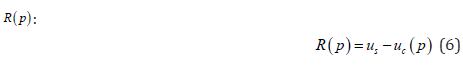
It should be noted here that the recorded displacements are limited to specific regions of the dam where the inverse pendulums are located. For the other regions, rational interpolation and extrapolation schemes have been followed to obtain the required unavailable data. Then, a traditional discrepancy function J was formulated as a quadratic form of obtained residuals as follows:
J(p )= R (p)T I R( p) (7)
where denotes the identity matrix. The solution is defined as a set of the variables {p} which minimizes the function J.
Long-Term deterioration: heterogeneously and orthotropically
After performing sensitivity analyses on the material parameters, it was revealed that the function J did not alter through the variation of the thermal expansion coefficient so this parameter was considered as a constant and equal to the value which obtained before from the previous study of the authors; thermal expansion coefficient= 1/˚C Labibzadeh et al. [39]. However, it was also pointed out that the magnitude of error function J changes noticeably when the Poisson’s ratios change. This is in contrast to the results of Oliveira et al. [40] and Garbowski et al. [23]. In the following, the obtained results of this study have been outlined in Table 1-3. For the sake of brevity, all the results are not presented here Table 1-3.
Table 1: Variation of function J versus the variation in Young’s modulus.

Table 2: Variation of function J versus the variation in Poisson’s ratios.

Table 3: Variation of function J versus the variation in shear modulus.

In the above tables, the word ‘zone’ points to the subdivisions numbered in Figure 2 and, are defined based on the Eq. 7 as below:
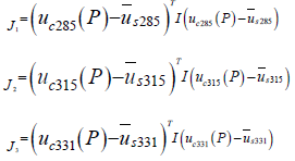 (8)
(8)denotes for example the computed relative displacement at the elevation 285 of the dam and refers to the recorded corresponding value with pendulums. The relation between the function J and is defined as below:
J = J1 + J2 + J3 (9)
In Table 1 and stand for the out-of-plane and in-plane elastic modulus respectively. As it is seen in that table, for each of this modulus, three different columns have been assigned. Each column indicates a zone of the dam (Figure 2); zone 1 denotes upstream, zone 5 marks central and finally zone 9 refers to downstream parts of the dam. uc331 , uc315 and indicate the relative displacement component in upstream-downstream direction of the dam, which have been computed by the proposed FE numerical model at the elevations 331, 315 and 285 of the dam in which there exist corresponding recorded values by the inverse pendulums of the dam i.e. uc331 , uc315 and. As it has been explained in the previous study, the relative displacements are in fact the difference between displacements of a particular point of the dam in two different days of the year 2007 which these days as are specified in Figure 6 are selected in such a way that the level of the reservoir is the same for these days but there is the maximum difference between the temperatures recorded by thermometers for them labibzadeh et al. [39]. J1 , J2 , J3 and error function J in Table 1 are those parameters that defined in eqs. (8) and (9). The same parameters have been used in Tables 2 & 3. In Table 2, and vHV refer to the Poisson’s ratios at out-of-plane and in-plane respectively see Figure 1. The last independent material parameter as defined by eq. (1) is the which denotes the out-of-plane shear modulus of the dam and used in Table 3. It is worth mentioning that the above tables have been shown in this paper in an order agrees with the order that inverse parameter identifications were performed in this attempt. Hence, the optimum or minimum of error function J can be found in the last table Table 3. This value (5.085E-07) is ten times smaller than the corresponding value obtained before by the authors Labibzadeh et al. [39], e.g. 1.37 E-06 based on the assumption of homogeneity and isotropy. Therefore, the question was asked in the beginning of this article now can be replied; the long-term deterioration process of concrete of the Dez dam is both heterogeneous and anisotropic. Figure 7-9 show the variations of the identified material parameters in a typical vertical section of the Dez dam.
Figure 7: Variation of the out-of-plane EH and in-plane EV elastic modulus (GPA) in a typical vertical section of the Dez dam

Figure 8: Variation of the out-of-plane vHV and in-plane vV Poisson’s ratios in a typical vertical section of the Dez dam.

Figure 9: 
Variation of the out-of-plane GH and in-plane GV shear modulus (GPA) in a typical vertical section of the Dez dam.

Based on the obtained results, the central part of the dam has not altered yet by any degradation due to aging. By moving from this central part to the downstream and upstream faces of the dam, it was observed that the elastic modulus decreased significantly. This reduction is more noticeable for the out-of-plane elastic modulus e.g. elastic modulus along the upstream-downstream direction in comparison to the in-plane elastic modulus (plane of isotropy) of the dam. With respect to the Poisson’s ratio on the other hand, it was revealed that the long-term damage of this parameter is not a heterogeneous and anisotropic process like to what observed for the elastic modulus and is a homogeneous and orthotropic damage. The out-of-plane Poisson’s ratio was obtained greater than in-plane correspondent value. A similar observation of Poisson’s ratio was obtained for the shear modulus. The out-of-plane shear modulus was obtained smaller than the in-plane corresponding value. These results confirm that the small thickness of the Dez dam and the actions of the main loads establish a state of stress which makes the long-term degradation of the Dez dam to be anisotropic. At the same time, the change in hydrostatic pressure and gravity loads along the height of the dam as well as the existence of a difference between the environmental conditions at upstream and downstream faces of the dam are responsibles for heterogeneity in that mentioned damage evolution.
Part II: Seismic Response of the Strength Degraded Dam
As it was demonstrated in the first part of this study, the strength of the Dez dam has been reduced during its service life. In this part, in order to evaluate the seismic behavior of the dam in its current condition, it was simulated against to an earthquake excitation. For this study, the horizontal and vertical acceleration records of Tabas earthquake have been used. These records are shown in Figure 10 & 11.
Figure 10: Tabas earthquake recorded at Tabas station.

Figure 11: Dam-reservoir-foundation model of the Dez dam.

The element types used for FE simulation of the dam-reservoirfoundation system have been outlined in Table 4. The length of the reservoir was considered as three times of the height of the dam in the above-mentioned FE simulation. Hence, the seismic waves travel to the far end of the reservoir are completely damped.
Table 4: Element library of the dam-reservoir-foundation model

To show the influence of long-term effects of the Environment
as well as reservoir interaction on the response of the dam three
different systems have been considered.
• System A: The dam with degradation strength.
• System B: The dam without degradation strength.
• System C: results of the dam with Hariri and Mirzabozorg’s
[41] assumptions.
The following response quantities for these systems have been
compared:
• Accelerations of the dam.
• Displacements at the crest of the dam.
• Envelope of max principal stress.
• Maximum crest displacement envelops.
• Periods of dam-reservoir-foundation.
Also, Hariri and Mirzabozorg’s [41] assumptions were:
• Dam is isotropic and homogeneous
• theories based on plasticity and fracture mechanics
• continuum crack modeled
• the un-damaged state
Figure 12 shows different reservoir levels.
Figure 12: Reservoir levels considered.

Maximum crest displacements envelop for different blocks for two states, with strength depredation and without depredation have depicted in Figure 13.
Figure 13: Maximum crest displacement envelop at level water 188m (17 blocks).

According to Figure 13, in all blocks, considering strength degradation increases the displacement of crest and this enlargement is more pronounced for the middle blocks. Time-history of crest displacement at the crest cantilever resulted from conducted analyses corresponding to maximum water reservoir level and the comparison between there states are shown in Figure 14.
Figure 14: Water elevation 188m.

It may be seen that the displacement responses at the crest begin from some initial values. These values are obtained from an initial analysis done under the static loading before the dynamic analysis started. The 30 first periods of dam-reservoir-foundation system in four different water levels for monolithic dam body were depicted in Figure 15.
Figure a-d 15:

In spite of changing of the depth of the reservoir, modal periods of the dam-reservoir-foundation system obtained in the current study by the assumption of strength degradation are smaller than the corresponding values obtained by Hariri and Mirzabozorg [41]. The measuring line for Figure 17-19 was shown in Figure 16.
Figure 16:Measure Line.

Figure 17a-d: Non-concurrent displacement envelope for upstream nodes.

Figure 18a-d: Non-concurrent velocity envelope for upstream nodes.

By changing the reservoir depth, different dam responses have
been calculated. Figure 17 shows non-concurrent envelopes of
displacement along the height of the crown cantilever of the dam
extracted from Hariri and Mirzabozorg [41], with and without
strength degradation assumptions in various performance levels.
In the considered systems and the depths of reservoir, the
amounts obtained by Hariri and Mirzabozorg [41] have the smallest
displacements and the dam with strength degradation have the
largest displacements. Figure 18 represents non-concurrent
velocity envelope along the height of the central cantilever.
The quantitative comparisons among the peak values of
different response quantities for Hariri and Mirzabozorg [41]
and the current model with strength degradation show Table 5
that the displacements, velocities, and accelerations get changed
significantly with the consideration of strength degradation (Figure
19).
Table 5:

Figure 19a-d: Non-concurrent acceleration envelope for upstream nodes.

For convenience of the readers in better investigating of the change in the seismic resistance of the Dez dam, the envelope of the non-concurrent maximum and minimum principal stresses on the upstream and downstream faces of the dam have been compared with the results obtained by Hariri and Mirzabozorg [41] in Figure 20 through 27. It should be mentioned that these researchers did not consider any degradation for the mass concrete of the dam. As it can be seen from Figure 20-23, current study shows considerable reduction in the compressive regions (blue colored) of the dam due to ageing effects.
Figure 20 a,b: Envelope of max principal (S1) Stress upstream and downstream Level of Water: 188m.

Figure 21 a,b:Envelope of max principal (S1) Stress upstream and downstream Level of Water: 155m.

Figure 22 a,b: Envelope of max principal (S1) Stress upstream and downstream Level of Water: 101m.

Figure 23 a,b: Envelope of max principal (S1) Stress upstream and downstream Level of Water: 56m.

Conclusions
In this paper, subsequent to the previous attempt done by the authors on the Dez dam Labibzadeh et al. [39] and based on that, an effective thermo-elastic inverse analysis has been implemented for in-detail elastic property identification of this dam after a long time being passed from its operation time. In this new work, the property of age-related degradation of the dam was investigated from the heterogeneity as well as anisotropy point of views. By reviewing the obtained results, it was revealed that the ongoing deterioration of the concrete material of the Dez dam is a heterogeneous and orthotropic process. Heterogeneity is due to the difference in the environmental conditions circumvented the dam as well as the change of hydrostatic and gravity loads along the height of the dam and anisotropy because of the shape of the dam and the state of stresses resulted from the permanent external loading exposed on the dam. Furthermore, the effects of this degradation were investigated in the seismic response of the dam. Obtained results in this stage demonstrated that the deterioration of the mass concrete of the dam leads to the enlargement of the tensile stresses in the dam which indicates a reduction in the seismic resistance and subsequently in the dam safety design factors (Figures 24-27).
Figure 24 a,b: Envelope of max principal (S3) Stress upstream and downstream Level of Water: 188m.

Figure 25 a,b:Envelope of max principal (S3) Stress upstream and downstream Level of Water: 155m.

Figure 26 a,b:Envelope of max principal (S3) Stress upstream and downstream Level of Water: 101m.

Figure 27 a,b:Envelope of max principal (S3) Stress upstream and downstream Level of Water: 56m

Acknowledgements
Author is so grateful to Yaqub Arab, the head and his assistants Ebrahim Barati Choobi and Kambiz Amiri in Dam Stability Control Center of Water & Power Authority of Khouzestan Province of Iran.
References
- Dam Safety Technology Development Program (2005) Material properties model of aging concrete. Rep. DSO-05-05, U.S. Dept. of Interior, Bureau of Reclamation, Technical Service Center, Denver, USA.
- Wittmann FH (1968) Surface tension, shrinkage, and strength of hardened cement paste. J Mater. Struct 1(6): 547-552.
- Pihlajavaara SE (1964) On the interrelation of the moisture content and the strength of mature concrete and its reversibility. Technical Rep. 76, VTT-The State Institute for Technical Research, Finland.
- Pihlajavaara SE (1974) A review of some of the main results of a research on the ageing phenomena of concrete: Effect of moisture conditions on strength, shrinkage and creep of mature concrete. Cem Concr Res 4(5): 761-771.
- Kuhl D, Bangert F, Meschke G (2003) Coupled chemo mechanical deterioration of cementitious materials. Part II. Numerical methods and simulations. Eng Fract Mech 70(7-8): 891-910.
- Nguyen VH, Nedjar B, Torrenti JM (2007) Chemo-mechanical coupling of leached concrete. Part II: Modelling. Nuclear Engineering and Design 237(20-21): 2090-2097.
- Chen Z, Ren Q (2007) Research on high arch dam failure probability based on failure mode. Key Engineering Materials 348-349: 597-600.
- Camara R, Oliveira SB (1992) Safety evaluation of arch dams under seismic actions. Earthquake Engineering, 10th World Conf, Balkema, Rotterdam, Netherlands, 4611-4616.
- Ghanaat Y (2004) Failure modes approach to safety evaluation of dams. 13th World Conf. on Earthquake Engineering, Vancouver, BC, Canada.
- ASTM (1985) Temperature effects on concrete. ASTM-Committee C-9, Philadelphia.
- Cerny R, Rovnanikova P (2002) Transport processes in concrete Spon Press New York.
- Ekstrӧm T (2001) Leaching of concrete, experiments and modeling. Report TVBM-3090. Sweden: Division of Building Materials at the Lund Institute of Technology.
- Ardito R, Maier G, Massalongo G (2008) Diagnostic analysis of concrete dams based on seasonal hydrostatic loading. Eng Struct 30(11): 3176-3185.
- Moshtagh M, Ghaemian M (2008) Effect of alkali-aggregate reactions in concrete dams using finite element method. Scientica Iranica, Sharif Univ Technol 15(1): 1-7.
- Wang JT, Feng J, Zhang C (2011) Seismic safety of arch dams with aging effects. Sci China Technol Sci 54(3): 522-530.
- Bond LJ, Kepler WF, Frangopol DM (2000a) Improved assessment of mass concrete dams using acoustic travel time tomography. Part I-Theory. Constr Build Mater 14(3): 136-144.
- Bond LJ, Kepler WF, Frangopol DM (2000b) Improved assessment of mass concrete dams using acoustic travel time tomography. Part II-Applications. Constr Build Mater 14(3): 147-156.
- Burman A, Maity D, Sreedeep S (2009) The behavior of aged concrete gravity dam under the effect of isotropic degradation caused by hygro-chemo-mechanical actions. Int J Eng Stud 1(2): 105-122.
- Gawin D, Pesavento F, Schrefler BA (2006) Hygro-thermochemo- mechanical modelling of concrete at early ages and beyond. Part I: Hydration and hygro-thermal phenomena. Int J Numer Methods Eng 67(3): 299-331.
- Gawin D, Pesavento F, Grymin W, Wyrzykowski M, Simoni L (2011) Numerical modeling of concrete degradation due to alkalisilica reaction in variable hygro-thermal conditions. Computer methods mechanics, Warsaw, Poland.
- Maier G, Ardito R, Fedele R (2004) Inverse analysis problems in structural engineering of concrete dams. Computational mechanics, WCCM VI in Conjunction with APCOM’04, Springer, Berlin.
- Fedele R, Maier G, Miller B (2006) Health assessment of concrete dams by overall inverse analyses and neural networks. Int J Fract 137(1-4): 151-172.
- Garbowski T, Maier G, Novati G (2011) Diagnosis of concrete dams by flat-jack tests and inverse analyses based on proper orthogonal decomposition. J Mech Mater Struct 6(1-4): 181-202.
- Alvin KF, Robertson AN, Reich GW, Park KC (2003) Structural system identification: From reality to models. Comput Struct 81(12): 1149-1176.
- Fedele R, Maier G (2007) Flat-jack tests and inverse analysis for the identification of stress states and elastic properties in concrete dams. Meccanica 42(4): 387-402.
- Fedele R, Maier G, Miller B (2005) Identification of elastic stiffness and local stresses in concrete dams by in situ tests and neural networks. Struct Infrastruct Eng 1(3): 165-180.
- Salawu OS (1997) Detection of structural damage through changes in frequency: A review. Eng Struct 19(9): 718-723.
- Ardito R, Bartalotta P, Ceriani L, Maier G (2004) Diagnostic inverse analysis of concrete dams with statical excitation. J Mech Behav Mater 15(6): 381-389.
- Ardito R, Cocchetti G (2006) Statical approach to damage diagnostic of concrete dams by radar monitoring: Formulation and a pseudo-experimental test. Eng Struct 28(14): 2036-2045.
- Naik TR (1985) Temperature effects on concrete. Philadelphia, PA: American society for testing and materials.
- Downie B (2005) Effect of moisture and temperature on the mechanical properties of concrete. MS thesis, Dept. of Mechanical and Aerospace Engineering, West Virginia Univ, Morgantown, WV.
- De Borst R, Peeters M (1989) Analysis of concrete structures under thermal loading. Comput Methods Appl Mech Eng 77: 293-310.
- Arch dam design (1994) US army corps of engineers. Washington (DC), pp. 20314-21000.
- Engineering and Research Center (1977) Office of Design and Construction Design criteria for concrete arch and gravity dams. Washington (DC): United states department of the interior bureau of reclamation.
- Ruiz MF, Muttoni A, Gambarova PG (2007) Relationship between nonlinear creep and cracking of concrete under uniaxial compression. J Adv Concr Technol 5:1-11.
- Dodds RK (1966) Measurment and analysis of rock physical properties on Dez Project, Iran. Testing Techniques for Rock Mechanics, ASTM STP 402, Am. Soc. Testing Mats, p. 52.
- Bangert F, Grasberger S, Kuhl D, Meschke G (2003) Environmentally induced deterioration of concrete: Physical motivation and numerical modeling. Eng Fract Mech 70(7) 891-910.
- Grasberger S, Meschke G (2004) Thermo-hygro-mechanical degradation of concrete: from coupled 3d material modelling to durability-oriented multified structural analyses. Mater. Struct./ Concr. Sci. Eng. 37:244-256.
- Labibzadeh M, Khajehdezfuli A, Khayat M (2014) Elastic strentgh diagnosis of the Dez concrete arch dam using thermal inverse analysis. Journal of Performance of Constructed Facilities (ASCE), 29(6) 04014167-1-04014167-12, DOI: 10.1061/(ASCE)CF.1943-5509.0000660.
- Oliveira S, Toader AM, Vieira P (2010) Finding the elastic coefficients of a damaged zone in a concrete dam using material optimization to fit measured modal parameters. 2nd International Conference on Engineering Optimization, September 6-9, Lisbon, Portugal.
- Hariri-Ardebili MA, Mizabozorg H (2011) Reservoir fluctuation effects on seismic response of high concrete arch dams considering material nonlinearity. Journal of Civil Engineering Research 1(1):1-20.


-

Mark E Smith
Bio chemistry
University of Texas Medical Branch, USA -

Lawrence A Presley
Department of Criminal Justice
Liberty University, USA -

Thomas W Miller
Department of Psychiatry
University of Kentucky, USA -

Gjumrakch Aliev
Department of Medicine
Gally International Biomedical Research & Consulting LLC, USA -

Christopher Bryant
Department of Urbanisation and Agricultural
Montreal university, USA -

Robert William Frare
Oral & Maxillofacial Pathology
New York University, USA -

Rudolph Modesto Navari
Gastroenterology and Hepatology
University of Alabama, UK -

Andrew Hague
Department of Medicine
Universities of Bradford, UK -

George Gregory Buttigieg
Maltese College of Obstetrics and Gynaecology, Europe -

Chen-Hsiung Yeh
Oncology
Circulogene Theranostics, England -
.png)
Emilio Bucio-Carrillo
Radiation Chemistry
National University of Mexico, USA -
.jpg)
Casey J Grenier
Analytical Chemistry
Wentworth Institute of Technology, USA -

Hany Atalah
Minimally Invasive Surgery
Mercer University school of Medicine, USA -

Abu-Hussein Muhamad
Pediatric Dentistry
University of Athens , Greece
