Lupine Publishers Group
Lupine Publishers
Menu
ISSN: 2637-4668
Short Communication(ISSN: 2637-4668) 
Comparison between: Concrete Flat-Slabs and Tunnel Form Construction (Tcf) Volume 2 - Issue 4
Hiba Alhawasli* and Khosroo Daneshjoo
- Faculty of Architecture, The Tarbiat Modares University, Iran
Received: June 15, 2018; Published: June 20, 2018
Corresponding author: Hiba Alhawasli, Faculty of Architecture, The Tarbiat Modares University, Tehran, Iran
DOI: 10.32474/TCEIA.2018.02.000142
Abstract
The concept of modern methods of construction seems to provide faster and more efficient construction increasingly in the construction industry. These modern methods provide features and solutions to the problems of cost, durability and speed but the choice of the most suitable system for building follows a number of requirements and conditions determined by the nature of the same construction and its specifications. This article analyzes two concrete building systems: concrete flat-slabs construction and tunnel form construction (TCF), but with a comparison methodology between both types of systems in the following aspects: method of construction, components contacts and particles of implementation, through an overview of both systems and their parts and the implementation mechanism of the construction to ultimately determine the appropriate place to use each one. All of building height, function, and speed required are important factors to determine the priority of one of these two systems over the other.
Keywords: Construction technique, Flat-slabs, Joints, Slab cycle, Tunnel Form
Introduction
Concrete structural systems must be durable, constructible, economical, and functional. The system selected must be strong and in many cases aesthetically pleasing. The system must have deflections that are within acceptable limits and in seismic areas must have the ability to absorb the large amounts of energy generated by seismic vents. Selection of a structural system can sometimes be a difficult process [1]. Each of the concrete flat-slabs construction and tunnel form construction (TCF) are in generally concrete building systems, but with a comparison methodology between both types of systems in the following aspects: method of construction, components contacts and particles of implementation, we are able to know the weaknesses and strengths of each of them to arrive at the end to find the right place for using each of them based on the results arising.
General Definition
Flat-Slab General Definition
A flat-slab is a part of the elevated concrete floor systems that can be classified as two parts that they are further divided into several types:
(a) Beam-Supported Floors: (one-way slab, two-way slab, oneway joist floor and two-way joist floor that called waffle slab).
(b) Beamless Floors: (two-way joist floor, flat plate and flatslab) (Figure 1).
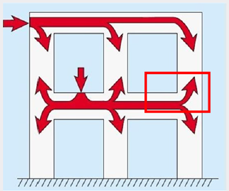
And this site-cast concrete is monolithic structurally; this means that there is continuity among elements allowing the loads to flow through the structure. This is accomplished because the walls, floors and columns all work together as a one-piece unit to transfer loads without bolted welded, pinned or grouted connections (Figure 2). A flat-slab is a slab and column structure with drop panels and column capitals at the slab and column connections (Figure 3a). The primary purpose of drop panels is to provide greater shear resistance at the columns, where the shear maximizes structurally, the drop panel must extend a minimum of one-sixth of the slab span in each direction and its drop below the slab must at least be 25% of the slab thickness, (Figure 3b), for formwork economy the drop depth is also based on lumber dimensions (Figure 3c). With round columns, however, manufacturers supply column forms that have built-in drop panels and column capitals (Figure 4). Flat-slab is generally used where the live loads are relatively high, such as in parking garages or storage or industrial facilities [2-4]. Concrete flat-slabs have been used since the mid (1900s) and are one of the most common floor systems employed in the construction of many multi- story buildings such as offices, hotels, and apartments throughout the world [5].
Figure 3: Typical details of a flat-slab and minimum code requirements for drop panel dimensions. (a) A typical flat-slab. (b) Minimum drop panel dimensions. (c) Drop depth of panel based on dimension lumber [2].

Tunnel Form General Definition
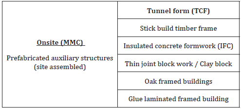
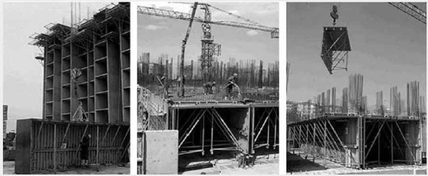
The tunnel form system is an industrialized construction technique in which structural walls and slabs are cast (in situ) simultaneously using steel forms composed of vertical and horizontal panels set at right angles. The tunnel form structural systems (i.e., box systems) having a load-carrying mechanism composed of reinforced concrete (RC) shear walls and slabs only [6]. Tunnel form is one of the modern methods of construction (MMC) that originated in the United Kingdom as a common term for offsite methods of construction and onsite methods of construction. Offsite (MMC) is prefabrication elements or parts of structures, constructed in factory, transported and assembled on site. Onsite (MMC) is building blocks and parts of structures takes place directly on site [7]. Various authors prepared studies about the classifications of modern methods of construction (MMC), part of these classifications are listed in the Table 1 [7], which shows the tunnel form as one of the prefabricated auxiliary structures (site assembled) that cast on site. This system is made of panels in both directions which are set at right angles and supported by struts and props. The main elements in such structure are wall elements as primary load carrying elements, and slabs which are almost the same thickness as the walls. These buildings do not have either beams or columns and this type of structure reduces the number of joints [8]. Each half of tunnel form looks like an upside down (L), the wall portion of the form is typically (2.4 to 3m) high, each form has wheels built in and a screw jack to adjust the elevation of the form. The two halves of the form are locked together with a special (roof lock) that also maintains flatness tolerances between the forms to within a few thousandths of millimeter. A critical piece of hardware on a tunnel form is an adjustable diagonal support extending from the wall to the deck form, it transfers the weight of the deck to the wall form and ultimately to the wall below the floor slab. Before a project begins, these supports are adjusted and cambered to account for the weight of the concrete on the deck (Figure 5).
Method of Construction
Flat-Slab System
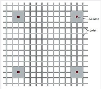
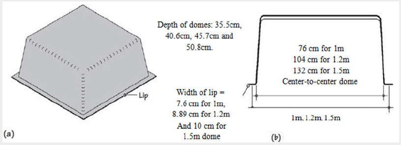
The concrete placement sequence in the flat-slab system has significant importance on the behavior of frames [1]. A waffle slab is more commonly constructed as a beamless slab (Figure 6). In a beamless waffle slab a few domes on all sides of a column are omitted so that the thickness of the slab at the columns is the same as the depth of the joists. The thickening of the slab at the columns provides shear resistance (against the slab punching through the columns) [2]. The formwork for the slab consists of glass fiber–reinforced plastic domes placed on a flat form deck with the lips butting each other (Figure 7). Like the pans, the domes can withstand repeated use, dome dimensions have been standardized to produce (0.9m, 1.2m) and (1.5m) center-to-center distances between domes in a variety of depths, the domes have a wide supporting lip on all sides and are laid on a flat-form deck [2].
Figure 7: Standard (GFRP) dome sizes for a waffle slab. Consult manufacturers for available sizes. (a) Three-dimensional view of fiberglass dome used as form for a waffle slab. (b) Section through dome [2].
IS 456:2000 code recommendations for proportioning flat-slab:
a) Thickness of flat-slab: the thickness of flat-slab shall be generally controlled by considerations of span to effective depth ratio.
b) Drops: the drops when provided shall be rectangular in plan and have a length in each direction not less than one third of the panel length in each direction. For exterior panels, with drops at right angles to the non -continuous edge and measured from center line of the columns shall be equal to one half the width of drop for interior panels [9].
Tunnel Form System
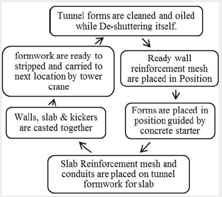
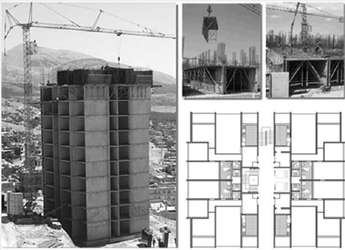
After the first ground level floor slab is placed, workers cast a (0.7 m) high curb where ever a wall is to be located. Reinforcement for a wall extends through the top of the curb, tying into the floor (reinforcement for walls is placed before curbs are cast and before the forms are put in position). The tunnel forms are then set (0.05m) above the floor against the curbs. Next workers attach steel block outs to one form wall for doorways, mechanical, plumbing and electrical vertical chases [10,11]. The doors have cam levers to collapse the bulkheads for easy removal afterwards. Tapered ties with both internal and external spacers join the tunnels together; tie spacing is typically on (1.2×1.8m) grids. Reinforcement for the deck above is placed after the tunnel forms are positioned then rough electrical and block outs for plumbing are the final steps. After placing concrete some contractors put tarps over the end opening of the tunnel and supply heat to the enclosure to accelerate strength gain in the concrete. Others increase the design strength of their concrete in order to achieve the (60%) of design strength (typically 84-98kg/cm²) needed to remove forms the morning after placement, to remove the tunnel forms workers lower the screw jacks so the wheels on the forms contact the floor, each half tunnel form is rolled out by exposing a (lifting hole) located in the top of the form at one-third of its length, then a crane lifts the form and moves it to the next location. As the forms are being moved out of the previous placement, workers spray form oil on the wall sections to read them for the next cycle (Figure 8).
Figure 8: Multistory tunnel building construction system and typical symmetrical story plan. Note: thick lines in plan indicate shear walls [10].
The Next Cycle
i. The tunnel forms are first cleaned and coated with form oil, and then they are placed in their positions by using the kicker as the guide
ii. The wall reinforcement is placed before the tunnel formwork is positioned, then reinforcement steel and electric conduits are set in their places on the tunnel form.
iii. Wall, slab and kickers are cast. The next morning the formwork is ready to be stripped and carried to the next location by a crane.
In accordance with the design, steel block outs may be installed on the formwork panels to form the plumbing openings see Figure 9.
Components Contacts and Particles of Implementation
Flat-Slab System
Most connections, if not all, are required to transfer an unbalanced moment in addition to a shear force between slab and column [12]. Connections between the column and the slab are formed of, drops: to resist the punching shear which is predominant at the contact of slab and column support, the drop dimension should not be less than one-third of panel length in that direction. Column heads: certain amount of negative moment is transferred from the slab to the column. To resist this negative moment the area at the support needs to be increased this is facilitated by providing column capital/heads.
Tunnel Form System
.This system is made of panels in both directions which are set at right angles and supported by struts and props. The main elements in such structure are wall elements, as primary load carrying elements, and slabs which are almost the same thickness as the walls. These buildings do not have either beams or columns and this type of structure reduces the number of joints [8]. Steel forms composed of vertical and horizontal panels set at right angles. Nonstructural components such as facade walls, stairs, and chimneys are commonly produced as prefabricated elements [13]. Creates walls and floor slabs typically without openings during the primary concrete placement, windows looking outside and interior doors or partitions are usually crafted from precast panels or lightweight concrete blocks, when architectural form allows it, doors may also be formed by leaving openings in the formwork during the primary casting [14].
The Strengths and Weaknesses
Flat-Slab System
The Strengths
a. No restrictions on the positioning “can minimize floor-tofloor heights” [13].
b. Reduced cladding costs and refabricated services components and finishes of the building [13].
c. Built faster because formwork is simplified and minimized [13].
d. Early striking and flying systems. The overall speed of construction will be limited by the rate at which vertical elements can be cast [13].
e. The more flexible floor systems as it provides the designer with the freedom in floor plan designs [15].
f. Allows architect to introduce partition walls anywhere required, allows owner to change the size of room layout and allows choice of omitting false ceiling and finish soffit of slab with skim coating [13].
The Weaknesses
a. Joints are often the weakest link in a structural system [1].
b. Effects of increasing levels by increasing the steel requirements in column and beams, for an eight storied building: a percentage increase of (69%) in steel reinforcement is observed compared to non-seismic design [16].
c. The cost and duration required for shoring, forming, pouring and stripping operations, in addition: post-tensioning operations increase the construction cost, duration and complexity [15].
d. The flat-slab system is susceptible to a type of strength failure around the connection of column to slab known as punching failure [12].
Tunnel Form System
The Strengths
e. A symmetrical configuration in horizontal and vertical planes that enables continuous flow of construction and better quality assurance [16].
f. Tunnel form buildings provide superior seismic performance [16].
g. Reducing deformation under earthquake load and shorter period of oscillation [8].
h. Due to reduction in slab cycle time tunnel formwork proves more time [17]; this construction technique greatly reduces construction time by as much as (50%) and the costs by (20%) relative to the conventional methods [14].
i. The total cost for the shell will almost always be less than with other forming systems [10].
j. Speed of construction with a small crew [10].
k. The speed of work and covering a large area (40-60 m3) in one procedure [8].
l. Low maintenance and a strong rigid structure, quietness is a strong selling point. There is no creaking or movement in the floors and concrete walls transmit little sound. Energy savings are also significant [10].
m. Relates to the repetitive nature of the work, there are fewer mistakes [10].
The Weaknesses
a. (42) floors and above would not be rational for shear wall buildings (or similar structures) constructed using tunnel form systems, in turn causes losses in terms of material, as the thickness of shear walls increases [13].
b. The total construction costs increase continuously with an increase in building height [13].
c. The most costly component is the reinforcing steel, on the other hand, the proportion of formwork costs decreases with an increase in the number of floors [13].
d. Incompliance forms and massive structure [8].
e. The tunnel form buildings are built in one construction cycle, and no increments or modifications are possible at a later stage [14].
f. The buildings have substantial separation distances between them when separated from adjacent buildings; the typical distance from a neighboring building is (10) meters [14].
g. The one absolute requirement for tunnel forming is an opening on the perimeter of the structure, allowing for the removal of the form, workers must be able to roll the forms out of the structure far enough to be handled by crane [10].
h. In a typical building of this type there are no elevators and (1- 2) fire-protected exit staircases. Internal staircases are the primary means of escapes during fires and other types of emergencies. In a number of instances owners have installed external spiral steel staircases when the internally provided staircases did not meet the size and space requirements of the official specifications [14].
Comparison between the Two Systems
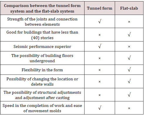
(Table 2)
Conclusion
Both systems based on removable models that speed up work, (TCF) construction technique reduces construction time by as much as (50%) and symmetrical configuration in horizontal and vertical planes enable continuous flow of construction and better quality assurance, and in flat-slab system built is faster because formwork is simplified and minimized, but the (TCF) outperform in terms of overall speed by covering a large area (40-60 m3) in one procedure and (300m2) of formwork each (24) hours. Cost increases in both systems with increasing height where shoring, forming, pouring and stripping operations increases, in addition to increases in steel reinforcement and slabs and shear walls thickness. But however (TCF) construction technique reduces construction costs by (20%) relative to the conventional methods. Tunnel form buildings provide superior seismic performance while joints in flat-slab system are often the weakest link in a structural system. Building established by (TCF) faces limitations, that building constructed using flat-slab system do not face, such as: (42) floors and above would not be rational, the buildings have substantial separation distances between them when separated from adjacent buildings that the typical distance from a neighboring building is (10) meters, incompliance forms and massive structure.
Acknowledgement
Let me thank Mr. Alaa Barkoky for all his support and assistance with the publication of this article.
References
- Thiruvengadam V, Wason JC, Gayathri L (2004) Cost Modeling Of Reinforced Concrete Buildings Designed For Seismic Effects. 13th World Conference on Earthquake Engineering. Vancouver, BC, Canada.
- Mehta M, Scarborough W, Armpriest D (2009) Building Construction: Principles, Materials, & Systems, Concrete Construction-II (Site-Cast and Precast Concrete Framing Systems) p: 528-548.
- Career Education Corporation, Designing Concrete Buildings. Schaumburg, IL, United States of America.
- Nasvik J (2003) Building with Tunnel Forms. Concrete construction.
- PE Scott W. Concrete Construction Engineering Handbook “Structural Concrete Systems”.
- Youssef M (2015) Seismic capacity of reinforced concrete interior flat plate connections. Bull Earthquake Eng 13(3): 827-840.
- Guan H, Loo Y (2003) Failure Analysis of Column-Slab Connections with Stud Shear Reinforcement. Canadian Journal of Civil Engineering.
- Kyjaková L, Mandičák T, Mesároš P (2014) Modern Methods of Constructions and Their Components. Journal of Engineering and Architecture 2(1): 27-35.
- Deshpande H, Joshi R, Bangar P (2014) Design Considerations for Reinforced Concrete Flat-slab Floor System. Int Journal of Scientific & Engineering Research 5(12).
- Joavanni D, Robertson I (2008) Retrofit of Flat-Slab Column Connections Using CFRP Studs to Resist Punching-Shear from Cyclic Loading. December, McConnell, 40, University Of Hawaii College Of Engineering, USA.
- Deshmukh A, Shalgar M (2016) Study of Tunnel Formwork versus Aluminium Formwork. International Research Journal of Engineering and Technology (IRJET) 3(12): 477-480.
- Ben Sasi O (2012) Tests of Interior Flat-Slab-Column Connections Transferring Shear Force and Moment. 37th Conference on Our World in Concrete & Structures. Singapore: CI Premier Pte Ltd p: 29 - 31
- Yüksel B, Kalkan E (2007) Pros and Cons of Multistory RC Tunnel-Form. The Structural Design Of Tall And Special Buildings.
- Yakut A, Gulkan P (2003) Housing Report Tunnel Form Building. Turkey: World Housing Encyclopedia an Encyclopedia of Housing Construction in Seismically Active Areas of the World.
- Klasanović I, Krausi, Nyarko H, Marijana (2014) Dynamic properties of multistory reinforced concrete tunnel-form building - a case study in Osijek, Croatia. Bauhaus Summer School in Forecast Engineering: Global Climate change and the challenge for built environment. p: 17-29.
- Yeşim İlerisoy Z, Tuna ME (2013) Construction cost of tunnel form buildings. Građevinar 65(2): 135-141.
- Aradhye T, Apte E (2016) Study of Advanced Tunnel Formwork System in High Rise Building. International Journal of Research in Engineering and Technology 5(5).

Top Editors
-

Mark E Smith
Bio chemistry
University of Texas Medical Branch, USA -

Lawrence A Presley
Department of Criminal Justice
Liberty University, USA -

Thomas W Miller
Department of Psychiatry
University of Kentucky, USA -

Gjumrakch Aliev
Department of Medicine
Gally International Biomedical Research & Consulting LLC, USA -

Christopher Bryant
Department of Urbanisation and Agricultural
Montreal university, USA -

Robert William Frare
Oral & Maxillofacial Pathology
New York University, USA -

Rudolph Modesto Navari
Gastroenterology and Hepatology
University of Alabama, UK -

Andrew Hague
Department of Medicine
Universities of Bradford, UK -

George Gregory Buttigieg
Maltese College of Obstetrics and Gynaecology, Europe -

Chen-Hsiung Yeh
Oncology
Circulogene Theranostics, England -
.png)
Emilio Bucio-Carrillo
Radiation Chemistry
National University of Mexico, USA -
.jpg)
Casey J Grenier
Analytical Chemistry
Wentworth Institute of Technology, USA -
Hany Atalah
Minimally Invasive Surgery
Mercer University school of Medicine, USA -

Abu-Hussein Muhamad
Pediatric Dentistry
University of Athens , Greece

The annual scholar awards from Lupine Publishers honor a selected number Read More...


