
Lupine Publishers Group
Lupine Publishers
Menu
ISSN: 2637-4668
Research Article(ISSN: 2637-4668) 
Application of Preplaced Aggregate Concrete to Convert the Ballasted Railway Tracks into Slab Tracks Volume 1 - Issue 5
Morteza Esmaeili1, Milad Hosein Esfahani2*, Ali Hemati2
- 11Railway Engineering School, Iran University of Science and Technology, Iran
- 2Ms.c Student of Railway Engineering, Iran University of Science and Technology, Iran
Received: February 27, 2018; Published: March 07, 2018
Corresponding author: Milad Hosein Esfahani, Railway Engineering School, Iran University of Science and Technology, Iran
DOI: 10.32474/TCEIA.2018.01.000121
Abstract
One of the most critical restrictions of ballasted railway tracks maintenance is the ballast undercutting and sieving over the railway bridges and tunnels. In recent years with respect to the development of in-place concrete slab track construction, using preplaced aggregate concrete technology is known as a new method to convert the ballasted railway tracks into slab track. Since no detail has been published regarding to design and construction of such systems by various railway owners, so the present study is allocated to this issue. In this matter, firstly some accomplished projects using this system has been reviewed and secondly, the detail evaluation of preplaced ballast concrete performance has been investigated in lab environment. In this former stage, by using the developed laboratory-scaled facilities, many cylindrical specimens have been constructed and tested. Consequently, their flow time and related compressive and splitting tensile strengths have been presented and the optimum injected mortar mix design have been reported.
Keywords: Preplaced aggregate concrete; Slab track; Flow time; Compressive strength; Splitting tensile strength
Introduction
Preplaced Aggregate Concrete (PAC) is referred to a kind of concrete making by first placing coarse aggregate in the formwork and then injecting a sand-cement mortar to fill the voids imprisoned between the coarse aggregate particles. In order to operate safely, it is highly essential to maintain railway tracks over specific periods of time so that any detected defects in track components become obviated [1]. Generally, maintenance activities in ballasted railway tracks is more important in comparison with ballast less ones, because the former is tend to geometrical defects like asymmetric settlement and twist due to flexible behavior of ballast under three- directional loads [2]. On the other hand, ballast fauling can reduce track vertical and transverse strength in wet weather condition by decreasing its resilency. This cause's track instability and vehicle derailment. Also, rise of passing traffic in busy lines can limit the total repair time, which brings track closure and passenger dissatisfaction [3]. All these factors privilege ballast less (slab) tracks to ballasted ones and propel engineers to use Preplaced Aggregate Concrete (PAC) technology so that the total life cycle cost and maintenance activity of railway tracks decrease over their lifetime.
History of Pac
In 1937, PAC was utilized to repair a tunnel in California. This kind of concrete was being consumed for repairing tunnel structures for many years. Then, USBR (United States Bureau of Reclamation) used this method to rebuild a part of Hoover dam. In 1946, this method was used to repair Barker dam in Colorado in which the mortar injection was finished after 10 days. US Army Corps of Engineers utilized this method to construct 34 bridge columns with 380000 cubic meters of concrete in 1951. From 1950 on, this method is commonly used in Japan, Australia and many other countries [4].
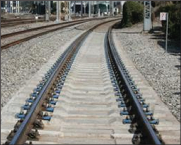
In railway engineering, this method has first utilized in Japan to convert few ballasted railway tracks into slab tracks about 40 years ago. In 1970, A, B and D types of PAC were executed, but there is no exact detail on their mix design and application procedure. In 1983, E type of PAC was reported as the advanced type of B one. In this type, the hot asphalt was replaced by cement paste to fill the voids [5]. In 1997, TC type of this concrete has broadly introduced in Japan railway industry. This track was first laid on the Tabata- Shinjuku-Tamachi sections of the Yamanote Line as part of phase 1 construction. In 2002, it was laid on the Tabata- Tokyo-Tamachi section of the Yamanote Line and the Chuo Kaisoku Line, Sobu Kankou Line, and Keihin-Tohoku Line as part of phase 2 construction. By 2008, 182 km of track for the Tokyo metro line had been laid [6]. In Korea, the development of quick-hardening concrete tracks for urban railways began in 2003. Since 2007, such track has been positioned in turnouts, tunnels, and earthwork sections of the Seoul Metro. In 2009, it was placed in a bridge section of the Yangsan Metro line 2 in Busan [7]. Since there is no reported mix design around the application of preplaced aggregate concrete in ballasted railway tracks, so in present study it is tried to find the optimum mortar mix design and this smatter a laboratory scale apparatus of PAC sample construction is developed (Figures 1 & 2).
Figure 1: Left: Barker dam in Colorado, Right: Bull Shoals dam turbine embedded by PAC method
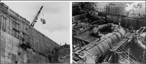
Figure 2: Metro line in Seoul
Pac Specifications
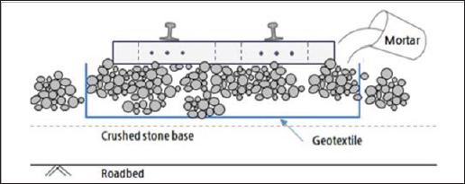
Unlike conventional concrete, PAC is made by first placing coarse aggregate into the formwork and then injecting a sand- cement mortar to fill the voids imprisoned between the coarse aggregate particles. This method is newly applied in voluminous projects like constructing bridge columns, massive foundations and in-situ transformation of ballasted railway tracks into slab tracks.After mixing the sand-cement mortar, it will be injected into the ballast material using air compressor so that the whole porosity imprisoned between coarse aggregate materials is filled. It is completely impossible to pour the mortar in gravity way since it will not fill voids properly (especially the water cement ratio of the mortar is low) (Figure 3).
Figure 3: Theory of concreting
PAC has got several advantages in comparison with the ordinary concrete. It has perfect homogeneity and will not be segregated if the amount of super plasticizer is controlled. Since the coarse aggregate is fixed in the formwork, PAC's drying and plastic shrinkage is half up to one third of ordinary concrete; so its cracking potential is much less than ordinary ones. This benefit makes PAC easy to repair and also become suitable for water constructions. Cooling and warming procedure of the injected mortar is also possible for different weather conditions by varying the temperature of mixing materials. Vibration is not needed for PAC because the air will get out of the concrete by mortar injection pressure. It can be outlined that PAC has higher modulus of elasticity, lower creep and Poisson ratio in comparison with the conventional concrete.
Materials and Proportioning
According to [4,8], the required characteristics of materials for making PAC are explained in tables below (Tables 1-3).
Table 1: Coarse aggregate characteristics [4].

Table 2: Fine aggregate characteristics [4].

Table 3: Cement characteristics [9].

Developed Laboratory Apparatus
The following laboratory apparatus [4,8,10] have been developed in Advanced Superstructure Laboratory (ASL) in School of Railway Engineering (SRE) in Iran University of Science and Technology (IUST) to simulate the process of mortar injection into the ballast.
Mortar mixing system
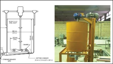
Mixing system of mortar comprises of a barrel, an electrical motor, a gearbox and the main stainless steel shaft with ellipseshaped blades. The electrical motor can rotate around its main axis with the rotational velocity of 1450r/min. This velocity must be reduced to approximately 250r/min in order to satisfy the recommended velocity mentioned in [8] For this purpose, it is essential to use a 1/7 gearbox to reduce its rotational velocity. Mixing procedure is done by the main shaft derived from the gearbox. The shaft is 118cm long and has two groups of ellipseshaped blades locating at the heights of zero and 30cm from bottom of the barrel. The whole mixing system elevated 2 meters above the ground so that the mortar moves into the injection cylinder by gravity. The mixing system is depicted in Figure 4.
Figure 4: Left: Recommended mixing system in [8], Right: Developed mixing system
Pressurized cylinder and sampling system
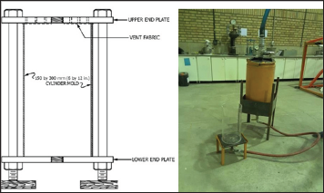
A high pressure cylinder is required to inject the mortar into the sampling system. Hence, a thick-wall cylinder is provided for mortar temporary storing and injecting. At the top of cylinder, the 2in mortar entrance valve, %in air entrance valve and safety valve are improvised. The cylinder endures 2 bars of pressure provided by air compressor, then the mortar pushes out as soon as the exit valve is opened. The sampling system consists of a Plaxi glass cylinder and two steel flanges which harness the cylinder. The height and diameter of cylinder are 40cm and 20cm respectively. The flanges are sealed in top and bottom of the cylinder and will be waterproofed using Polyurtan mastic in order not to exude the mortar. These systems are illustrated in Figure 5.
Figure 5: Left: Details of sampling system, Right: Developed cylinder and sampling apparatus
Materials and Mix Design
In order to investigate the effect of ballast grading in the strength of PAC, it is necessary to test its high and low gradation ranges which bring injection possibility. In this paper, two groups of ballast grading and two water cement ratios in mortar are investigated. For mortar preparation, 900kg per cubic meters of cement is used with 1st and 4th ballast grading as coarse aggregate and Firoozkooh sand as fine aggregate. To provide mortar fluidity, Polycarboxilate-based super plasticizer is used depending on the w/c ratio. The grading tables of coarse and fine aggregate are presented as follows (Tables 4 & 5).
Table 4: Ballast grading.

Table 5: Firoozkooh's sand grading.

Water cement ratios of 0.35 and 0.42 are assumed as the high and low ranges, respectively. w/c of 0.42 is the ratio in which there is no need to superplasticizer for mortar injection and w/c of 0.35 is the least injectable ratio by which adding specified amount of superplasticizer, the mortar injection can be easily possible. The utilized mix designs are pointed out in Table 6.
Table 6: Mix design.

Results And Discussion
After injecting the sand-cement mortar into the ballast and curing the specimens, their related compressive strength must be measured at the ages of 1, 3 and 28 days [9,10]. It is highlighted that in each age in the specified w/c ratio, three specimens were broken and their mean value is reported. Figures 6 & 7 show the compressive strength of PAC specimens versus their related age in different w/c ratios and ballast gradings. In Figure 6, it can be resulted that the compressive strength of PAC specimens has been dramatically increased in their early ages in group 1 of ballast grading in both w/c ratios, while this behavior is not observed in group 4. In both ballast grading groups and w/c ratios, there is a slight increase in compressive strength in later ages. Figure 7 depicts that w/c ratio of 0.35 has got more compressive strength comparing with w/c of 0.42. The sharp increase of compressive strength in group 1 of ballast is also clearly visible. The strongest PAC specimen constructed by this method is one which have compressive strength of 15MPa.
Figure 6: Compressice strength of PAC specimens for two ballast groups

Figure 7: Compressice strength of PAC specimens for two ballast groups

Conclusion
In this paper, an overview and a history of preplaced concrete was firstly presented. Secondly, the main features of PAC components were described and the recommended apparatus was defined. Subsequently, the developed laboratory apparatus of mortar creation and injection was depicted. Then, the characteristics of designs were introduced. Finally, the compressive strength of PAC specimens was reported. According to figures 5 and 6, group 1 of ballast has got better results in compressive strength in both early and late ages in comparison with group 4. It is also concluded that w/c ratio of 0.35 has got higher compressive strength comparing with w/c ratio of 0.42. It can be mentioned that lower w/c ratios cause the specimens become more strong in early ages.
References
- Zakeri, M Rezazadeh (2016) Track Maintenance Methods. IUST Press, Iran.
- EA Odaka T (2003) Development of Low-maintenance Railway Tracks Using the Full-size Railway Track Testing. JREA 46: 23-25.
- JM Sadeghi (2008) Ballasted Railway Tracks, Fundamentals of Analysis and Design. IUST Press, Iran.
- ACI (1997) Guide for the Use of Pre Placed Aggregate Concrete for Structural and Mass Concrete Applications. American Concrete Institute, USA.
- (1975) Properties of Quick Hardening Cement, Asphalt Grout, and Concrete and Their Practical Problems. Railway, Technical Research Report, Railway Technical Research Institute, Japan.
- MK, AH (2003) Development of Low-maintenance Tracks. Journal of east Technical Review 6: 28-35.
- TT, IK, Fuchigami, MY (2012) Development of Pre-Packed Concrete Track bed for Shinkansen. Railway Technical Research Institute Report, 26(2): 19-24.
- ASTM (2016) Standard Practice for Proportioning Grout Mixtures for Preplaced-Aggregate Concrete,” United States, USA.
- ASTM (2015) Standard Specification for Portland cement. United States, USA.
- ASTM, "Standard Practice for Making Test Cylinders and Prisms for Determining Strength and Density of Preplaced-Aggregate Concrete in the Laboratory. United States, USA.

Top Editors
-

Mark E Smith
Bio chemistry
University of Texas Medical Branch, USA -

Lawrence A Presley
Department of Criminal Justice
Liberty University, USA -

Thomas W Miller
Department of Psychiatry
University of Kentucky, USA -

Gjumrakch Aliev
Department of Medicine
Gally International Biomedical Research & Consulting LLC, USA -

Christopher Bryant
Department of Urbanisation and Agricultural
Montreal university, USA -

Robert William Frare
Oral & Maxillofacial Pathology
New York University, USA -

Rudolph Modesto Navari
Gastroenterology and Hepatology
University of Alabama, UK -

Andrew Hague
Department of Medicine
Universities of Bradford, UK -

George Gregory Buttigieg
Maltese College of Obstetrics and Gynaecology, Europe -

Chen-Hsiung Yeh
Oncology
Circulogene Theranostics, England -
.png)
Emilio Bucio-Carrillo
Radiation Chemistry
National University of Mexico, USA -
.jpg)
Casey J Grenier
Analytical Chemistry
Wentworth Institute of Technology, USA -
Hany Atalah
Minimally Invasive Surgery
Mercer University school of Medicine, USA -

Abu-Hussein Muhamad
Pediatric Dentistry
University of Athens , Greece

The annual scholar awards from Lupine Publishers honor a selected number Read More...


