Lupine Publishers Group
Lupine Publishers
Menu
ISSN: 2637-4668
Research Article(ISSN: 2637-4668) 
Application of Non-Destructive Testing and Signal Processing Characteristics to Identify Defects and Microstructural Changes in Advanced High Strength Steels Volume 2 - Issue 4
Isaac Garcia C1* and Zhanfang Wu1,2,3
- 1Mechanical Engineering and Materials Science Department, University of Pittsburgh, Pittsburgh, Pennsylvania 15261, USA
2 School of Materials Science and Engineering, Northeastern University, China
3 National Engineering and Research Center of Continuous Casting Technology, Central Iron & Steel Research Institute, China
Received: June 23, 2018; Published: August 01, 2018
Corresponding author: Isaac Garcia C, Ferrous Physical Metallurgy Group, Mechanical Engineering and Materials Science Department, University of Pittsburgh, Pittsburgh, Pennsylvania 15261, USA
DOI: 10.32474/TCEIA.2018.02.000143
Abstract
Nondestructive testing (NDT) and signal processing were used to detect, locate and define surface and internal defects in unidirectionally solidified laboratory ingots. These defects included cracks, voids, coarse non-metallic inclusions and heavy chemical and microstructural segregation. Many NDT techniques have been developed and used to assess the presence of these defects. The factors responsible for these defects are often related to mechanical, thermal, or transformation stresses during the solidification process of continuously cast steels. The high thermal stresses result from the difference expansion or contraction behavior caused by the frequency of the temperature fluctuation during solidification. In order to study the effect of these temperature fluctuations to the defects, a specially designed copper chill mold that simulates the solidification rate of continuously cast slabs was designed. In addition, a NDT-UT system was applied to localize and describe the presence of defects caused by thermal or transformation stresses. Furthermore, the signal processing analysis was used to characterize the changes in microstructure and hardness. The results of those studies are presented and discussed.
Keywords: Defects; NDT; Microstructure; Thermal stresses; Internal crack
Introduction
Advanced high strength steels (AHSS) are a special class of steels used in the fabrication of safety critical components used in the automotive industry. The success of producing these components starts with the quality of the continuously cast slab. The presence of severe internal defects during solidification could cost significant yield losses. Their prevention entails one of the most important challenges in the development of modern high strength steels. The reduction or elimination of severe slab cracking has been the focus of large number of studies [1-5]. A number of studies [2-9]. have shown that thermal or transformation stresses during the solidification of the slab are perhaps one of the most important cause of internal cracking. Several methods for analyzing this problem have been presented in the literature. For example, Won et al. [5]. used a two-dimensional coupled thermo-elastoplastic finite element model and analyzed the crack susceptibility during steel slab solidification. Li and Thomas [6]. used a thermal resistance model to deal with the heat transfer coefficient between the shell and the cooling water in the mold. Lei et al. [7]. set up a 2D transient thermo-mechanically coupled FEM to calculate the temperature and stress distribution in a chamfered mold. Gur and Tekkaya [8].
combined thermal analysis and microstructural analysis with small strain elastic-plastic analysis to predict the temperature distribution, the progress of phase transformation, the evolution of internal stresses and residual stresses during quenching for axisymmetric steel components. Kristiansson [9]. presented a finite element model in which a strip of elements was used to model a slice of the casting. Boundary conditions were imposed restricting axial displacements to be equal above and below the slice. Internal defects in continuously cast slabs can have a strong effect on the performance of the steel during thermo-mechanical processing. Therefore, attempts to find a suitable method to identify, quantify and characterize the defects have been the subject of many studies. The use of NDT (Non-destructive Testing) technique such as ultrasonic signal testing is practical and efficient method for examining bulk material in different applications, especially in the case of relatively thick slab castings. The work conducted in this paper attempted to study the effect of temperature fluctuations on the formation of internal defects during the unidirectional solidification of an experimental steel. In order to conduct this study an experimental Cu-chill mold was developed and built. To aid in the analysis of the experimental unidirectional solidified steel ingot, a NDT-UT system was used to localize and describe the presence of defects caused by thermal or transformation stresses.
Experimental Procedure
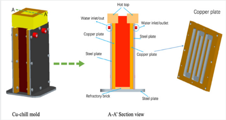
Figure 1 is the schematic diagram of the designed unidirectional experimental device (Cu-chill mold). The copper plate and the steel plate are joined together and the channel was machined on the copper plate for the circulation of cooling water. Insulating bricks were used to prevent the loss of heat on the mold narrow sides during solidification process. After the completion of the pouring, the ingot will be ready for NDT-UT scanning when it is cooled sufficiently
Non-Destructive Testing
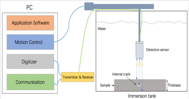
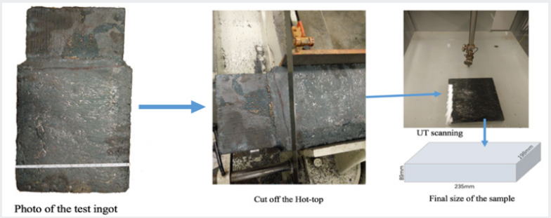
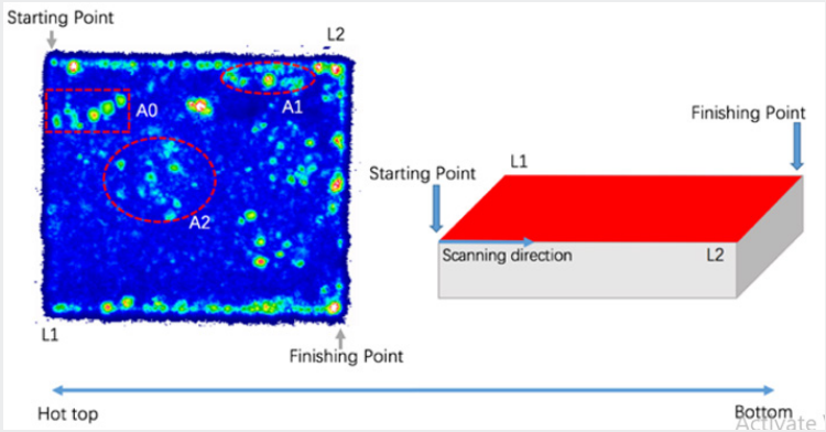
In ultrasonic NDT test techniques, ultrasonic signal waves are emitted from a sensor made up of a transducer, which are mainly piezoelectric, and a receiver. Parts of the emitted waves are reflected off the samples by surfaces of anomalies to the transducer or other electronic receivers and other portions of waves are scattered and damped into the structure. The schematic view of the ultrasonic mechanism can be seen in Figure 2. In this experimental research work, ultrasonic NDT was used to detect and locate internal defects on the test ingot which was obtained from the Cu-chill mold unidirectional solidification experiment (Figure 3). shows the preparation of the sample and scanning process. The hot top of the sample was cut off before testing and final size of the sample is 89mm(thickness)×198mm(width)×235mm(length) (Figure 4). is the general result of NDT-UT testing. Area 0 (A0) is the hole formed by thermocouple of temperature measurement during the solidification experiment. Area 2 (A2) is the central shrinkage defect during solidification process. Area 1 (A1) was analyzed in detail using a technology called “gating” for accurate capture and display of the specific location of defects in the test ingot.
Signal Processing Characteristics
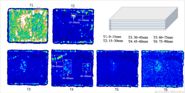
As the thickness of the test sample increases, there is a possibility of interference between returned waves from a point within the sample to the sensor’s receiver and waves reflected from odd angles of other anomalies located in other points in the test ingot. These interactions of sound wave could result in resonance phenomena, amplifying the reflected waves, and increasing the error in the image analysis data. To minimize these errors, the control software was set to generate imaginary sections, “gates”, through the thickness by arranging a decibel range filter through the thickness of the test ingot. The data captured for each point by the receiver is collected for the total thickness of the gate. The number of gates used in the ultrasonic test depends on the material geometry and its thickness. The accuracy of the testing increases in direct relationship with the number of gates. To avoid losing any information of defects through entire thickness of the slab, an overlap range between adjacent gates was considered (Figure 5). is the scanning result used the “gate” in the ultrasonic testing.
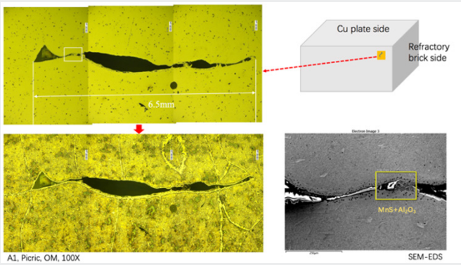
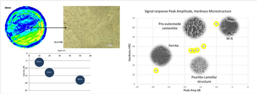
It can be seen from this figure that the location of defects is easy and accurate to locate after scanned by using the “gate” technology. The crack in Figure 6. shows a length of about 6.5mm. This figure clearly shows films of pro-eutectoid ferrite are decorating the prior austenite columnar grains. SEM-EDS analysis of the inclusions near the crack revealed that the inclusions are composite non-metallic inclusions of alumina and manganese sulfide. In the functional process of subsequent development of NDT signal characterization technology, NDT has been successfully applied to characterize the change of microstructures for our test steel (Figure7). shows the microstructures and hardness corresponding to different signal response in terms of Peak Amplitude (dB). In summary, by combining the UT scanning results, a better understanding of the formation of the crack observed and shown in Figure 6. can be explained as follows: During the cooling process, heat is transferred from inside to the surfaces of the steel ingot by conduction. Cooling of the ingot generates a thermal stress distribution around the region of the steel matrix containing inclusions. Different cooling rates will produce different thermal stress values and distributions specially at the grain boundary containing films of pro-eutectoid ferrite and inclusions.
This can affect the interaction of the inclusion and the matrix during the cooling process because of their differences in material (elastic and plastic) properties, especially thermal conductivity and thermal expansion coefficient. With fast cooling rate during solidification experiment, this condition modifies the thermal stress distribution in the region with inclusions compared to one without any inclusions or with different inclusion type and volume fraction, as well as, thermal stress concentration around those inclusions. In the case of the increasing thermal stress concentration or large volume shrinkage, cracks will be generated along the boundary between inclusions and steel matrix [10,11]. Different heat treatments used to produce a variety of microstructures were also subjected to NDT signal processing. Each microstructure has a “finger print” that is easily identified by the proper signal processing. The signal response and hardness is shown in Figure 7.
Conclusion
In this work, a NDT-UT system was used to localize and describe the presence of defects caused by thermal or transformation stresses. To minimize these errors and make the location of defects become easy and more accurate to locate, the control software was set to generate imaginary sections through the thickness by arranging a decibel range filter through the thickness of test ingot using the “gating” technology. During the cooling process, heat is transferred from inside to the surfaces of the steel ingot by conduction. Cooling of the ingot generates a thermal stress distribution around the region of the steel matrix containing inclusions. Different cooling rates will produce different thermal stress values and distributions. The presence of increasing thermal stress concentration at the hard inclusion- steel matrix interface is the source of the void and cracks at the interface region. In the functional process of subsequent development of NDT signal characterization technology, it has been successfully applied to characterize the change of microstructures and hardness for the test steel in terms of peak amplitude.
Acknowledgement
The authors would like to thank the Ferrous Physical Metallurgy Group at the University of Pittsburgh and its industrial sponsors for their support.
References
- Thomas BG (2001) Continuous Casting, The Encyclopedia of Materials: Science and Technology 2: 1595-1599.
- Yamanaka A, Nakajima K and Okamura K (1995) Critical strain for internal crack formation in continuous casting. Ironmaking and Steelmaking 22(6): 508-512.
- Won YM, Kim KH, Yeo T and Oh KH (1998) Effect of cooling rate on ZST, LIT and ZDT of carbon steels near melting point. ISIJ International 38(10): 1093-1099.
- Won YM, Han HN, Yeo T and Oh KH (2000) Analysis of solidification cracking using the specific crack susceptibility. ISIJ International 40(2): 129-136.
- Bernard C, Hiebler H, Wolf M (1996) Simulation of shell strength properties by the SSCT test. ISIJ International 36(l): S163-S166.
- Li CS, Thomas BG, Metall. Mater. Trans B 35: 1151.
- Lei S, Zeng S, Han ZW, Yan JW, Feng K, et al. (2013) Contin. Cast 380: 5-11.
- Gur CH, Tekkaya A E (1996) Finite element simulation of quench hardening. Steel research 67(7): 298- 306.
- Kristiansson JO (1982) Thermal stresses in the early stage of solidification of steel. Journal of Thermal Stresses 5(3-4): 315-330.
- Allazadeh MR, Garcia CI, Anthony Deardo (2009) Analysis of Stress Concentration around Inclusions due to Thermally Induced Strain to the Steel Matrix. Journal of ASTM International 6(5): 1-12.
- Baker TJ, Charles JA (1974) Further Aspects of Inclusion Deformation. Metals Techno1: 425-431.

Top Editors
-

Mark E Smith
Bio chemistry
University of Texas Medical Branch, USA -

Lawrence A Presley
Department of Criminal Justice
Liberty University, USA -

Thomas W Miller
Department of Psychiatry
University of Kentucky, USA -

Gjumrakch Aliev
Department of Medicine
Gally International Biomedical Research & Consulting LLC, USA -

Christopher Bryant
Department of Urbanisation and Agricultural
Montreal university, USA -

Robert William Frare
Oral & Maxillofacial Pathology
New York University, USA -

Rudolph Modesto Navari
Gastroenterology and Hepatology
University of Alabama, UK -

Andrew Hague
Department of Medicine
Universities of Bradford, UK -

George Gregory Buttigieg
Maltese College of Obstetrics and Gynaecology, Europe -

Chen-Hsiung Yeh
Oncology
Circulogene Theranostics, England -
.png)
Emilio Bucio-Carrillo
Radiation Chemistry
National University of Mexico, USA -
.jpg)
Casey J Grenier
Analytical Chemistry
Wentworth Institute of Technology, USA -
Hany Atalah
Minimally Invasive Surgery
Mercer University school of Medicine, USA -

Abu-Hussein Muhamad
Pediatric Dentistry
University of Athens , Greece

The annual scholar awards from Lupine Publishers honor a selected number Read More...


