
Lupine Publishers Group
Lupine Publishers
Menu
ISSN: 2637-4668
Research Article(ISSN: 2637-4668) 
A New Passive bar Damper Device for Alleviation of Structural Damages of Structures Subjected to Seismic Motions Volume 1 - Issue 3
Khaled Ghaedi1*, Ahad Javanmardi1, Zainah Ibrahim1, AnasShaiban2, Usman Hanif1 and S Kashif Ur Rehman1- 1Department of Civil Engineering, University of Malaya, Malaysia
- 2Structural Engineering Division, Asia Pacific Engineering Consortium, Malaysia
Received: February 03, 2018; Published: February 15, 2018
*Corresponding author: Khaled Ghaedi, Department of Civil Engineering, University of Malaya, Malaysia
DOI: 10.32474/TCEIA.2018.01.000115
Abstract
Passive energy dissipation devices have been successfully implemented in buildings around the world to reduce structural response, primarily due to earthquakes, but also for wind and other dynamic loading conditions. Passive systems do not require any external sources of power to operate and mitigate dynamic loadings. The focus of this study is to propose a new passive energy dissipation device, called bar damper (BD), for seismic response modification. A brief description of concept, placement, material properties, test setup and loading protocol of the proposed damper are presented. Also, the finite element (FE) analysis by means of FE analysis package, ABAQUS, was conducted to show the device effectiveness on the response reduction under applied load. From the results, it could be concluded that, the device dissipate a significant amount of energy together with a high strength capacity without degradation of stiffness.
Keywords: Bar damper; Earthquake; Passive device; Dynamic loading; Energy dissipation system
Introduction
Earthquake event, as one of devastated natural hazards, is not predictable [1]. Therefore, structural engineers have significantly concerned about seismic damages of civil structures. Structural vibration control devices have been proposed to dissipate such a huge input energy to structures including, active, passive, and semi-active and hybrid vibration control systems. In active and semi-active systems, device needs to be supported by an external force or power to resist earthquake load. Unlike, passive systems do not require any external power and they operate as a secondary function or member of structures; reducing seismic input energy. As a result, the use of passive control devices to reduce seismic response of structures under seismic motions is becoming progressively widespread as they are not required any external energy applied and they are activated once seismic loads are set to the structure [2,3]. Further developments of these systems in different aspects such as design, theory, hardware, installation and specification have authorized important applications to industrial plant, bridges, and buildings. Such application can currently be seen in almost all seismically active zones around the globe, but primarily in the United States, Japan, New Zealand and Italy. Remarkable benefits have been proved while retrofitting of existing buildings are required as well as designing structures with high importance such as critical bridges, defense installations, hospitals and emergency response services.
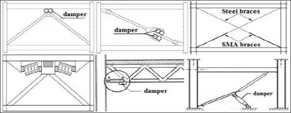
From the architectural point of view, major proposed structural controls including active and semi-active systems are designed to be installed at certain location of structures, as many of them are located in X, V or Z forms. (Figure 1) shows a few examples of installed devices proposed by different researchers [4-7]. Such installations restrict spaces which have to be used in structures and architectures must carefully consider the issue. Use of passive systems, particularly metallic dampers, as supplemental energy dissipating device is one of the earliest approaches adopted in seismic resilient design. Originally manufactured by Bechtel Corporation, ADAS damper is an evolution of earlier X-plate used as a damping source for piping systems [8]. Yielding of metals is one of the most effective, simple and economical mechanisms to dissipate earthquake input energy. The research in metallic passive energy dissipative devices has been conducted over the last three decades. Numerous metallic dampers have been proposed and installed [9,10]. Alongside Triangle Added Damping and Stiffness (TADAS), Added Damping and Stiffness (ADAS) dampers are the most commonly used metallic dampers in seismic design. Steel plate ADAS dampers have been the focus of many researchers in augmenting the energy absorbing capacity of a building. The aim of including metallic seismic energy absorbing devices in a structure is to take advantage of the hysteresis of metals to dissipate seismic input energy in specially designed and detailed regions of a structure and to avoid inelastic behaviour in the primary gravity load-resisting elements [11]. In designing structures for seismic loads, it is assumed that part of the seismic input energy is absorbed by specially designed structural elements through plastic deformation or hysteretic behaviour. Examples of these plastic energy absorbing elements are plastic hinges forming in beams of rigid frames, in concentric braces and in shear walls.
Figure 1: Placement of structural control systems in different locations.
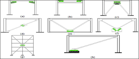
This conventional design method has several shortcomings, such as considerable strength and stiffness degradation of the elements, low hysteretic damping and damage to gravity-load carrying members that can cause collapse of the structure in severe earthquakes [12]. Apart of other structural control techniques, several metallic energy dissipative dampers were developed during the last decades [13-17]. As mentioned, popular devices include the hourglass shape ADAS device [18], its variant the triangular shape TADAS [19], Honeycomb damper [20] and Buckling Restrained Brace [21]. These devices are mainly designed to be incorporated into the bracing system of structural frames. Other devices were developed for installation between beams and columns in a frame structure [22]. On the other hand, some researchers have made use of alternative materials in device fabrication, such as lead, low-yield steel, copper and shape memory alloys to improve the performance [23-27]. The main goal of the present paper is to propose and examine a new metallic passive damper to deliver operative control of structures under minor and major vibration loadings; wind and strong motions. It comprises of the investigation on the behaviour of the damper subjected to cyclic deformations with stable and large energy dissipating cycles at minimum cost. It is noted that, the proposed damper not only opens the architectures' hand to use all spaces of design, but the location of the proposed passive damper can easily be changed, by changing the main parameters of the damper (bar arrangement, bar diameter, bar height, etc.) and it makes possible to place damper in various places. Examples of possible installation of bar damper (BD) are presented in Figure 2.
Figure 2: Examples of potential applications of BD.
Bar Damper (BD)
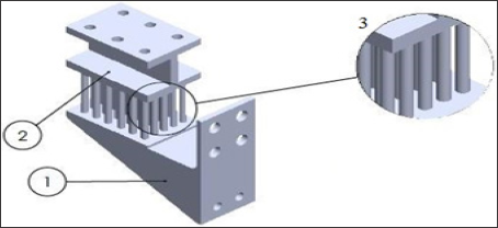
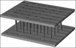
The device consists of three parts, i.e., steel bars and plates, such that the bars are sandwiched between two steel plates (Figure 3). The bars may differently arrange to achieve an optimum design with higher energy dissipation. The plates are extended to attach the frames of the structures. The inelastic cyclic deformation dissipates energy mainly through flexure of the steel bars. In order to behavior control of the damper, several parameters may be operated such as damper length, damper width, bars' height, bars' spacing, bars’ diameter, etc.
Figure 3: Overall view of the BD device with 1) bottom plate 2) top plate 3) solid bars (Patent application No.: PI 2016702928).
Bar Damper (BD)
Experimental test and numerical analysis was carried out to examine the device behavior. To this end, the device was subjected to a cyclic displacement protocol following FEMA-461 [28]. (Figures 4a & 4b) depicts the device in experimental and numerical analysis, where the FE software, ABAQUS was used for numerical analysis. Therefore, steel elements were modeled as 3D8R elements, which were eight-node quadrilateral reduced integration solid elements. The FE model of the device is shown in Figure 5.
Figure 4: BD under (a) Experimental test and (b) Numerical analysis.
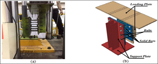
Figure 5: BD Modeling in ABAQUS.
Results and Discussions
Hysteresis behavior
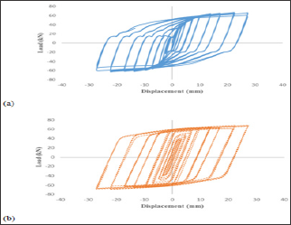
The first test was performed on the BD specimen with thirty- nine plastic cycles aimed up to the target displacement for 50 mm, although the specimen was failed at cycle 28 in step 9. (Figures 6a & 6b) show the force-displacement hysteresis curve of the BD under experimental cyclic displacement test and FE analysis. It is observed from the figure that, the specimen, experimentally, has stable behavior with no degradation in stiffness and strength up to 27.4 mm with maximum load capacity of 64.84kN. Similarly, the numerical analysis shows the accuracy of the work, where the load-displacement values of the specimen is appeared to be 68.38 kN and 25.33 mm, respectively.
Figure 6: Hysteresis behavior of the BD obtained from (a) Experimental test and (b) FE analysis.
Equivalent viscus damping and ductility
The equivalent viscus damping can be obtained from the hysteresis loop through the below equation:

In which, Ed and Es are energy dissipated per cycle and elastic dissipated energy, respectively. Based on this equation and considering (Figure 6) the viscous damping ratio or loss factor for BD specimen was found to be 50%. This means that, the BD was capable to dissipate input energy by 50%. In addition, the ductility of the device was obtained from Equation 2:

Where dmax is the plastic or maximum displacement and dy is the yield displacement of the device under cyclic load. In the present study, the maximum and yield displacement of the BD was 27.4 mm and 0.5 mm. These values give an acceptable ductility level of the device, i.e., 54.7. This shows the BD device is capable of dissipating seismic energy like or even better than available devices in the market such as, fluid Viscus dampers, friction dampers, whereas the BD is very simple-manufactured and economical. In the present paper an attempt has been made to introduce a new type of metallic damper, thus it is recommended to verify the device, a series of cyclic shear tests should be applied to the damper device. Table 1 indicates the summary of the obtained results, where, k,is the initial stiffness of the device, Py is the yield force and Nc is the cycle that BD failed. It can be seen from the table that, the numerical analysis with good agreement with the experiment results can be used for further studies. It is also noted that, The BD specimen failed at cycle 28, however, by changing the parameters of the device, it can be predicted that the specimens could be able to withstand far more. Figure 7 shows the deformation of the BD under cyclic displacement.
Figure 7: Deformation of tested specimen under cyclic loading.
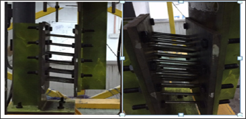
Table 1: Bar damper performance in the experimental and numerical study.

Summary and Conclusion
A steel-based energy harvester device; bar damper (BD) was proposed and examined. Solid bars were used as the main component, where they demonstrated good ductility and a very constant performance under cyclic loading. It has been confirmed from the analyses that, the cyclic behavior of the device can be precisely simulated by means of the constitutive model, comprising the effect of strain range, and isotropic and kinematic hardening. These properties can impact the device behavior subjected to cyclic deformations through finite element analysis. Additionally, the device considering different parameters can be used in other applications. By means of these considerations alongside with good deformations, a FE models of the BD prototypes shoed a good agreement with experiment results.
Acknowledgment
The authors gratefully acknowledge financial support from the Fundamental Research Grant Scheme, Ministry of Education, Malaysia (FRGS - Project No. FP004-2014B), Postgraduate Research Grant (PPP-Project No. PG177-2016A) and University of Malaya Research Grant (UMRG-Project No. RP004A-13AET).
References
- Ghaedi KZ Ibrahim (2017) Earthquake Prediction Earthquakes Tectonics Hazard and Risk Mitigation. pp. 205-227.
- Ghaedi KZ Ibrahim, H Adeli, A Javanmardi (2017) Invited Review Recent developments in vibration control of building and bridge structures. Journal of Vibro engineering 19(5): 3564-3580.
- Gordan M, HA Razak, Z Ismail, K Ghaedi (2017) Recent developments in damage identification of structures using data mining. Latin American Journal of Solids and Structures 14(13): 2373-2401.
- Choi H, J Kim (2010) New installation scheme for viscoelastic dampers using cables. Canadian Journal of Civil Engineering 37(9): 1201-1211.
- Ling YH, HH Ling (2012) Progress on Study and Application of Shape Memory Alloy in Passive Energy Dissipation. Applied Mechanics and Materials 198-199: 3-8.
- Maleki SS, Mahjoubi (2013) Dual pipe damper. Journal of Constructional Steel Research 85: 81-91.
- Barmo A, IH Mualla, HT Hasan (2015) The Behaviour of Multi-Story Buildings Seismically Isolated System Hybrid Isolation (Friction, Rubber and with the Addition of Rotational Friction Dampers). Open Journal of Earthquake Research 4(1): 1-13.
- Stiemer SF (1981) Experimental behaviour of a spatial piping system with steel energy absorbers subjected to a simulated differential seismic input (UCB/EERC-81/09).
- Boardman PR, BJ Wood, AJ Carr (1983) Union House A cross braced structure with energy dissipaters. Bulletin of the New Zealand National Society for Earthquake Engineering 16(2).
- Martines Romero E (1993) Experiences on the use of supplemental energy dissipaters on building structures. Earthquake Spectra 9(3): 581-625.
- Maleki S, S Bagheri (2010) Pipe damper Part I: Experimental and analytical study. Journal of Constructional Steel Research 66(8-9): 10881095.
- Aiken ID, DK Nims, AS Whittaker, JM Kelly (1993) Testing of Passive Energy Dissipation Systems. Earthquake Spectra 9(3): 335-370.
- Bagheri S, M Barghian, F Saieri, A Farzinfar (2015) U-shaped metallic- yielding damper in building structures Seismic behavior and comparison with a friction damper. Structures 3: 163-171.
- Bagheri S, A Hadidi, A Alilou (2011) Height wise distribution of stiffness ratio for optimum seismic design of steel frames with metallic yielding dampers. Procedia Engineering 14: 2891-2898.
- Basu D, PRM Reddy (2016) A New Metallic Damper for Seismic Resilience Analytical Feasibility Study. Structures 7: 165-183.
- Curadelli RO, JD Riera (2004) Reliability based assessment of the effectiveness of metallic dampers in buildings under seismic excitations. Engineering Structures 26(13): 1931-1938.
- Sahoo DR, T Singhal, SS Taraithia, A Saini (2015) Cyclic behaviour of shear-and-flexural yielding metallic dampers. Journal of Constructional Steel Research 114: 247-257.
- Bergman D, S Goel (1987) Evaluation of cyclic testing of steel plate devices for added damping and stiffness. The University of Michigan, USA.
- Tsai CS (1993) Innovative design of viscoelastic dampers for seismic mitigation. Nuclear Engineering and Design 139(2): 165-182.
- Kobori T, S Kamagata (1992) Dynamic Intelligent Buildings Analytical Simulator. Computer Aided Civil and Infrastructure Engineering 7(4): 265-281.
- Clark P, I Aiken, F Tajirian, K Kasai, E Ko, et al. (1999) Design procedures for buildings incorporating hysteretic damping devices.
- Koetaka Y, P Chusilp, Z Zhang, M Ando, K Suita, et al. (2005) Mechanical property of beam-to-column moment connection with hysteretic dampers for column weak axis. Engineering Structures 27(1): 109-117.
- Briones B, J De la Llera (2013) Analysis, design and testing of an hourglass-shaped ETP-copper energy dissipation device. Engineering Structures 79: 309-321.
- Chan RWK, F Albermani (2008) Experimental study of steel slit damper for passive energy dissipation. Engineering Structures 30(4): 10581066.
- De la Llera JC, C Esguerra, JL Almazan (2004) Earthquake behaviour of structures with copper energy dissipaters. Earthquake Engineering & Structural Dynamics 33(3): 329-358.
- He H, X Wang, X Zhang (2016) Energy Dissipation Performance of Combined Low Yield Point Steel Plate Damper Based on Topology Optimization and Its Application in Structural Control. Advances in Materials Science and Engineering 2016(9): 1-16.
- Qian H, H Li, G Song, W Guo (2013) Recentering Shape Memory Alloy Passive Damper for Structural Vibration Control. Mathematical Problems in Engineering 2013: 1-13.
- FEMA (2007) Interim protocols for determining seismic performance characteristics of structural and non structural components. pp. 461.

Top Editors
-

Mark E Smith
Bio chemistry
University of Texas Medical Branch, USA -

Lawrence A Presley
Department of Criminal Justice
Liberty University, USA -

Thomas W Miller
Department of Psychiatry
University of Kentucky, USA -

Gjumrakch Aliev
Department of Medicine
Gally International Biomedical Research & Consulting LLC, USA -

Christopher Bryant
Department of Urbanisation and Agricultural
Montreal university, USA -

Robert William Frare
Oral & Maxillofacial Pathology
New York University, USA -

Rudolph Modesto Navari
Gastroenterology and Hepatology
University of Alabama, UK -

Andrew Hague
Department of Medicine
Universities of Bradford, UK -

George Gregory Buttigieg
Maltese College of Obstetrics and Gynaecology, Europe -

Chen-Hsiung Yeh
Oncology
Circulogene Theranostics, England -
.png)
Emilio Bucio-Carrillo
Radiation Chemistry
National University of Mexico, USA -
.jpg)
Casey J Grenier
Analytical Chemistry
Wentworth Institute of Technology, USA -
Hany Atalah
Minimally Invasive Surgery
Mercer University school of Medicine, USA -

Abu-Hussein Muhamad
Pediatric Dentistry
University of Athens , Greece

The annual scholar awards from Lupine Publishers honor a selected number Read More...


